27 minute read
Steering/Body/Controls

The following steering components should be inspected periodically to ensure safe and proper operation. A.Steering wheel secure. B.Steering has equal and complete full-left and full-right steering capability. C.Steering sector mounting bolts tight. D.Ball joints not worn, cracked, or damaged. E.Tie rods not bent or cracked.
F.Knuckles not worn, cracked, or damaged. G.Cotter pins not damaged or missing. H.Steering wheel tilt locks securely. The frame and welds should be checked periodically for damage, bends, cracks, deterioration, broken components, and missing components.
Front Bumper
REMOVING 1.Remove the hood and grille (see Hood and Grille). 2.Disconnect the headlights.
WT463
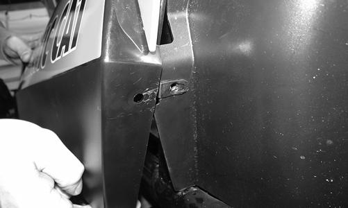
3.Using a suitable prying tool, pry the clips out from between the wiring harness and the frame. Press the clips downward to remove from frame.
WT454
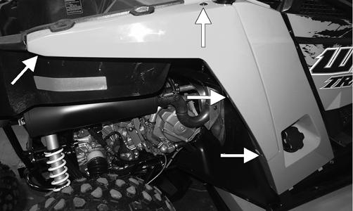
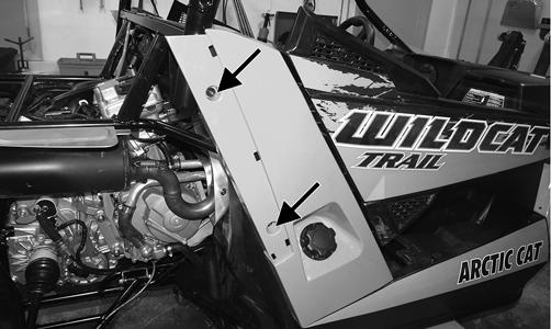
4.Remove the cap screws from both sides securing the front fenders to the frame.
WT453A
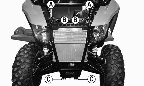
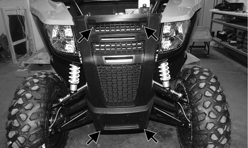
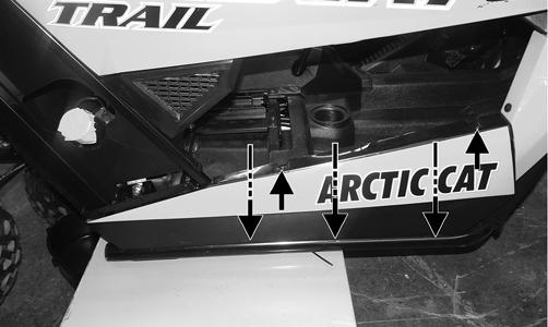
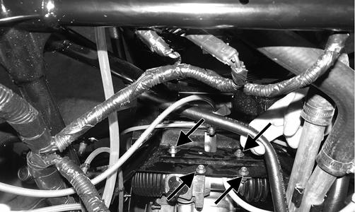
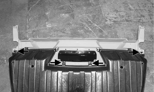
5.Remove the cap screws (A, B, and C) and discard the lock nuts from (A). Remove the bumper.
WT548A
INSTALLING 1.Place the bumper frame into position and with the existing cap screws and new lock nuts (A), finger-tighten at this point.
WT548A
2.Install the lower bumper cap screws (C); then tighten the upper and lower bumper cap screws to 20 ft-lb. 3.Install the cap screws and nuts securing the radiator to the frame (B). Tighten to 8 ft-lb. 4.Install the cap screws securing the front fenders to the frame; then tighten securely. 5.Connect the headlights. 6.Using the existing cap screws, secure the grille and tighten securely. 7.Install the hood and secure with the quarter-turn fasteners
Hood and Grille
REMOVING/INSTALLING HOOD 1.Turn the two quarter-turn fasteners counterclockwise and remove hood.
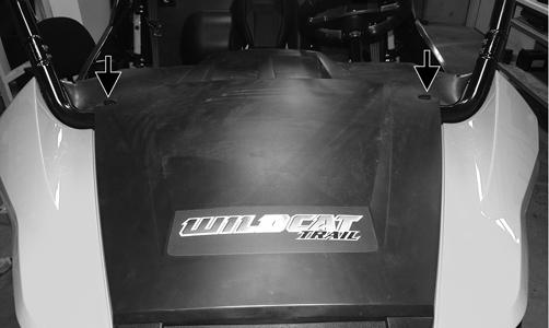
WT226A
2.Insert the hood tabs into the grille and lay the hood down flat. Turn both of the fasteners clockwise securing the hood.
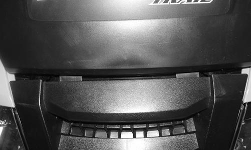
WT251
REMOVING GRILLE Remove the fasteners securing the grille; then remove the grille.
WT256A
CLEANING AND INSPECTING GRILLE Clean any dirt or debris from the grille webbing. This helps air flow to the radiator and oil cooler.
INSTALLING GRILLE Place the grille into position and secure it using the existing cap screws. Tighten all hardware to 60 in.-lb.
Body Panels
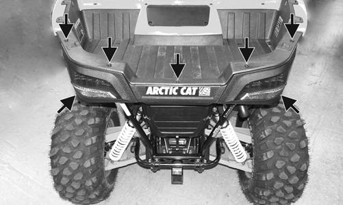
REMOVING REAR BODY PANELS 1.Remove the seats.
2.Remove the push pins and cap screws securing the rear fenders.
WT209A
! WARNING
The heat deflector under the right-rear fender has sharp edges and can cause serious injury if care is not taken.
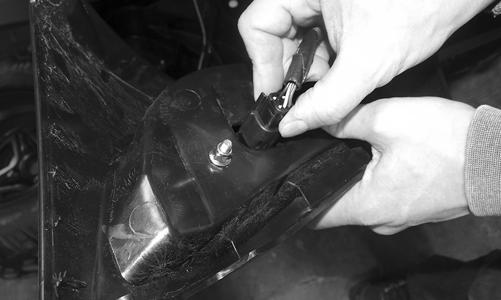
3.Remove the cap screws securing the taillight/brakelight assembly to the frame and disconnect the harness.
WT101A
WT222
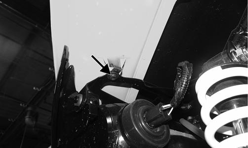
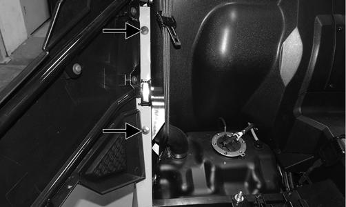
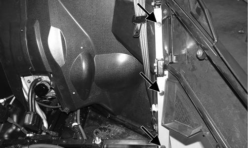
4.Remove the fasteners securing the right rear body panel.
WT241A
WT227A
5.Loosen the gas tank filler hose clamp and slide it down towards the tank.
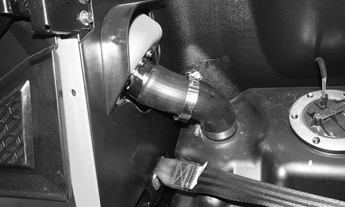
WT244
6.Remove the panel from the frame while also pulling on the filler hose. Seal off the hose to prevent objects from entering the hose.
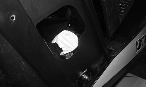
WT246
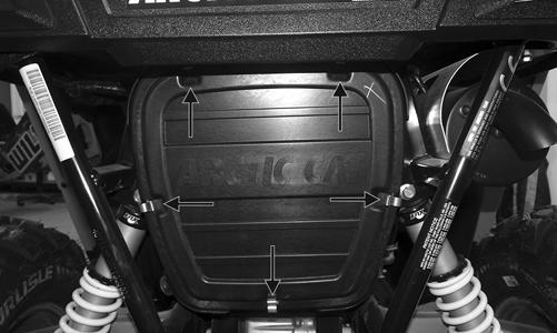
7.Remove the air pre-filter cover.
WT028A
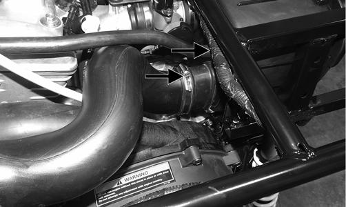
8.Loosen the clamp securing the clutch air intake tube to engine; then pry the tube off of engine. Account for the clamp.
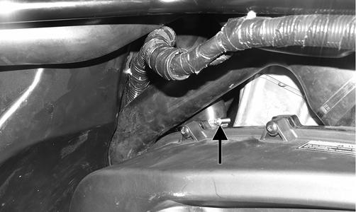
WT487A
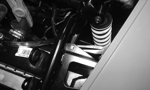
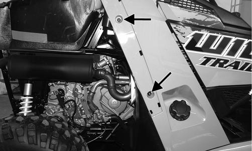
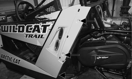
9.Remove the fasteners securing the left rear body panel.
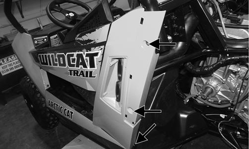
WT250A
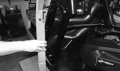
10.Remove the panel with the air/clutch intake tubes.
INSTALLING REAR BODY PANELS 1.If removed, install the clutch air intake tube through the left rear body opening and secure it with the plate and existing cap screws. Tighten securely.
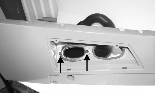
WT484A
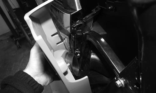
2.Install the tabs of the body panel into the slots in the side panel; then route the air intake clutch tube to the engine.
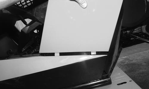
WT490
WT486
3.With the panel tabs in place, press the panel towards the frame and maneuver the air intake tube inside the boot.
WT485
4.Secure the panel to the frame and pre-filter cover with the existing cap screws and push pins.
WT488A
WT489A
5.Install the clutch intake tube onto the engine and secure it with the clamp. Tighten securely.
WT487A
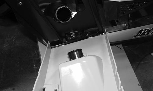
6.Install the left rear fender and secure it with the existing hardware. 7.Install the tabs of the body panel into the slots in side panel; then insert the plastic insert into the gas tank filler hose. Tighten the clamp and install the gas cap.
WT245
8.Secure the panel to the frame with the existing cap screws and push pins.
WT491A
WT489A
9.Install the right rear fender and secure with the existing hardware; then install the seats.
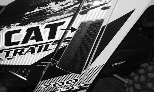
REMOVING SIDE PANELS To remove a side panel, remove the cap screws and push pins securing the side panel to the frame; then remove the panel.
WT257A
INSTALLING SIDE PANELS 1.To install a side panel, install the side panel tabs into the front upper side panel slots.

WT211
NOTE: Make sure the bottom of the side panel is on
the outside of the inner splash panel.
WT212
2.Secure the side panel using the existing cap screws and push pins. Tighten all hardware to 60 in.-lb.
Dash/Switches
REMOVING 1.Remove the hood; then remove the steering wheel (see Steering Wheel in this section).
WT338A
3.Remove the door latches and discard the cap screws.
WT010
4.Remove the fasteners and push pins securing the dash to the frame.
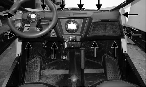
WT014A
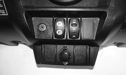
5.Disconnect the LCD gauge, ignition switch, and 12-volt accessory plug.
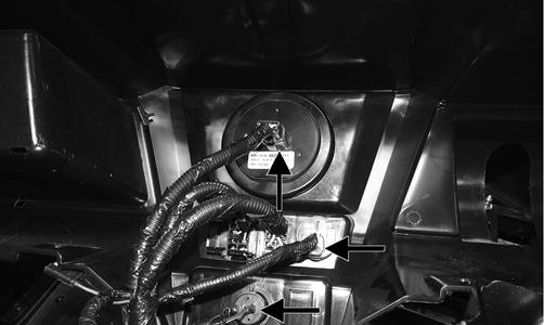
WT336A
6.Using an appropriate tool, push the bottom dash tabs in; then push the top tabs in and press the rocker switches through the dash. Disconnect the rocker switches and remove the dash.
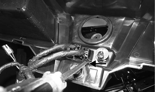
WT337A
INSTALLING 1.Install the switches into the appropriate locations.
Push the switches into the dash until they snap into place.
WT341
2.Connect the 12-volt accessory plug, ignition switch, and LCD gauge. 3.With the steering shaft slid through the dash, install the dash and secure it with the existing fasteners. 4.Using new “patch-lock” cap screws, install the door latches. Adjust the doors (see Doors in this section); then tighten to 8 ft-lb. 5.Using a new lock nut, install the tilt assembly and tighten to 10 ft-lb.
WT338A
6.Install the steering wheel (see Steering Wheel in this section); then install the hood.
Center Console
REMOVING 1.Remove the seats and engine access panel.
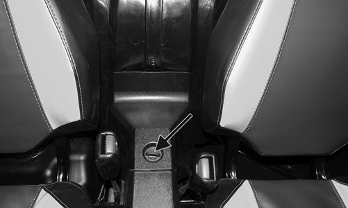
WT037A
2.Loosen the jam nut below the shifter knob; then unscrew the shifter knob.
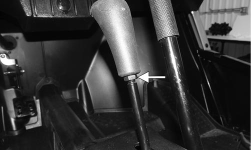
WT274A
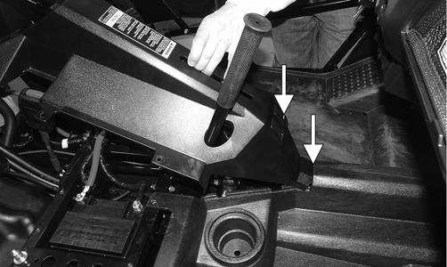
3.Remove the fasteners securing the center console; then remove the console.
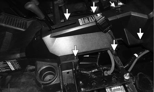
WT281A
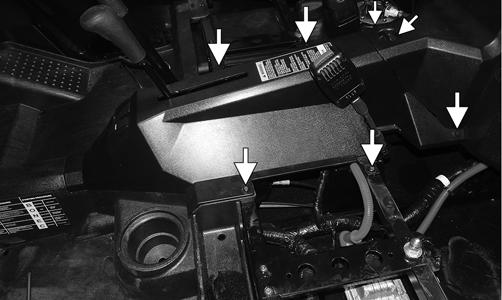
INSTALLING 1.Install the center console over the passenger hand-hold making sure the reverse override switch is connected and the front tab is properly inserted under the floor plastic.
WT286A
2.Secure the console with the existing cap screws and push pins. Install the engine access panel and secure with the quarter-turn screw.
WT281B
3.Install the shifter knob so the “P” is facing forward; then tighten the jam nut to 8 ft-lb. 4.Install the seats.
Rack and Pinion Assembly
REMOVING 1.Secure the vehicle on a support stand to elevate the front of the vehicle; then remove the front wheels.
WT330A
3.Remove the steering wheel, dash, and steering shaft. 4.Remove the cap screws securing the rack and pinion to the frame and remove from either side. Discard the lock nuts.
WT369A
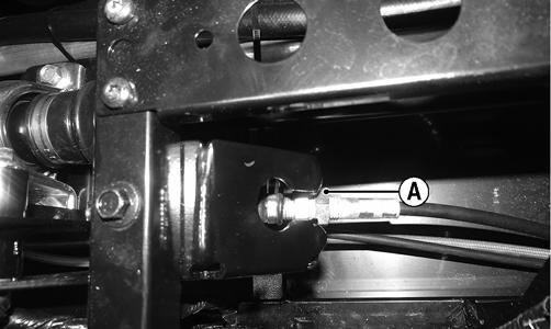
5.Support the steering rack assembly in a suitable bench vise; then remove the clamp (A) and cut the cable tie (B). Slide the boot to the center of the tie rod.
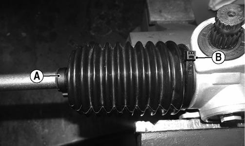
WT373A
6.While holding tie rod end (A), loosen jam nut (B) and remove the tie rod end (A).
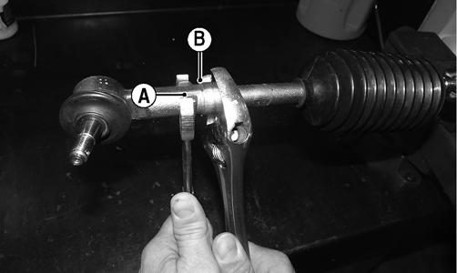
WT366A
7.Remove the inner tie rod from rack.
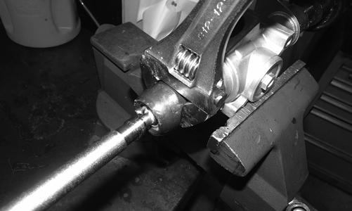
WT367
INSPECTING 1.Inspect the input shaft splines for excessive wear or signs of misalignment. 2.Inspect the slide mechanism for pitting, excessive wear, or worn bushings. 3.Rotate the input shaft from center to full left and right checking for any binding or catching. 4.Check for loose cap screws on rack and pinion housing. 5.Check for seal damage or lubricant leaks. NOTE: The steering assembly (rack and pinion) is
not repairable and must be replaced as an assembly; however, the tie rods and boots are replaceable.
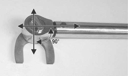
INSTALLING 1.With the threads coated with red Loctite #271, thread the tie rod onto the rack and tighten with a crow-foot to 37 ft-lb.
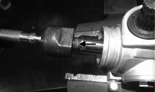
WT370A
NOTE: Always attach the crow-foot to the torque
wrench with the open end 90° to the torque wrench handle to ensure accurate torque application.
PR528A
2.Install the boot onto the rack and secure with the clamp and nylon ties.
WT373A
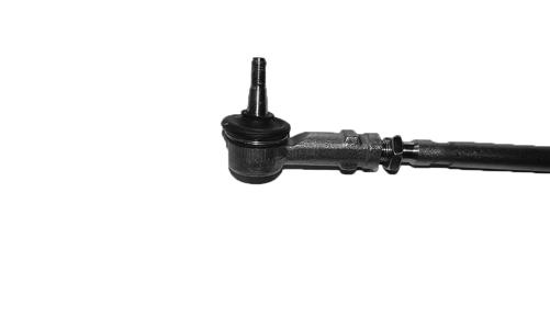
3.With the jam nuts on the inner tie rod, install the tie rod ends on to the inner tie rods. Do not tighten at this point.
WT569
4.Center the tie rods in the steering rack assembly and align the white paint line on the pinion with the white paint line on the rack housing. 5.Install the rack and pinion assembly into the vehicle; then using new lock nuts, secure to the frame and tighten to 25 ft-lb.
WT369A
6.Install the steering shaft, dash, and steering wheel. 7.Tighten the tie rod jam nut to 8 ft-lb. 8.Install the tie rod ends into the hubs; then with the threads coated in red Loctite #271, tighten the castle nuts to 55 ft-lb and secure with a new cotter pin. 9.Install the wheels and tighten the wheel nuts in 20 ft-lb increments to a final torque of 40 ft-lb (steel wheel), 60 ft-lb (aluminum wheel w/black nuts), or 80 ft-lb (aluminum wheel w/chrome nuts). Adjust front wheel alignment (see Front Wheel Alignment). 10.Remove the vehicle from the support stand.
Steering Wheel
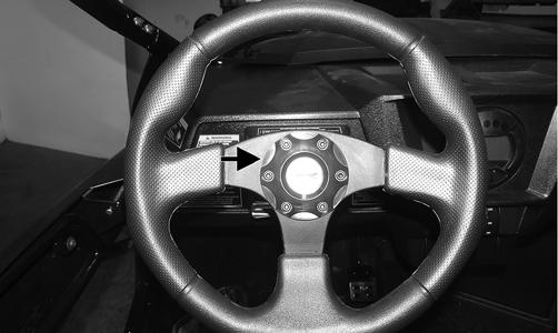
REMOVING 1.Remove the steering wheel cover; then mark the steering shaft and steering wheel for installing purposes.
WT298A
NOTE: Any time steering components are disassem-
bled, all connecting components should be marked for proper alignment during assembling.
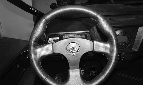
2.Remove the hairpin clip from the steering shaft; then remove the nut securing the steering wheel and remove the steering wheel.
INSPECTING 1.Inspect the steering wheel for cracks, missing padding, or broken spokes. 2.Inspect the splines for wear. 3.Check that the steering wheel is not bent.
INSTALLING 1.Install the steering wheel aligning the two match marks; then secure the steering wheel. Tighten to 25 ft-lb.
NOTE: If a new steering wheel is being installed,
mark the wheel as close as possible to the old wheel mark; then check for proper positioning with the front wheels straight forward.
2.Install the hairpin clip on the steering shaft.
WT297
NOTE: If the hole in the steering shaft does not
align with the slots in the nut, tighten the nut slightly until the next slot aligns with the hole.
Steering System
NOTE: Thoroughly troubleshoot the EPS prior to
replacing the EPS assembly (see Electrical System) as there are several possible external causes for system failure.

REMOVING EPS NOTE: Before removing the EPS assembly, ensure
the front wheels are aligned to the front.
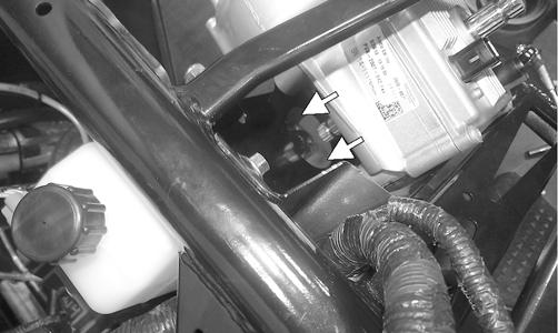
1.Remove the steering wheel, hood, and dash. 2.Remove the cap screws and discard the lock nuts securing the upper steering shaft to the frame.
WT604B
5.Remove the EPS assembly from the vehicle. NOTE: The EPS is a non-serviceable component; it
must be replaced as an assembly.
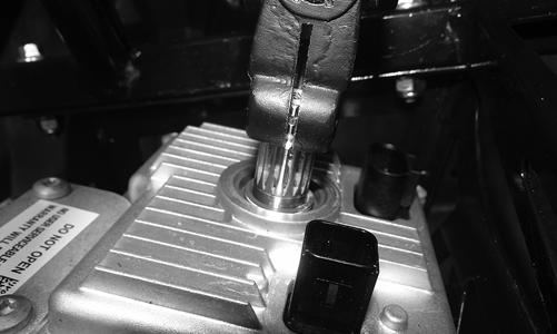
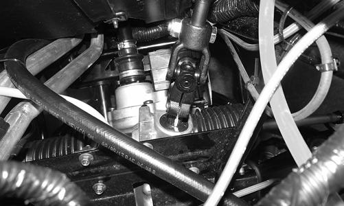
INSTALLING EPS 1.Place the EPS assembly into position being sure to align the timing mark of the EPS assembly with the opening of the steering shaft. Secure with cap screws but do not tighten at this point.
WT607A
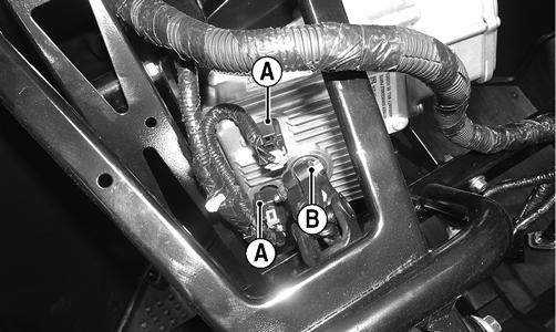
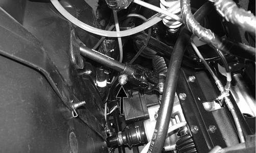
3.Unplug the electrical connections (A); then remove the cap screw and discard the lock nut (B).
WT603A
WT608A.
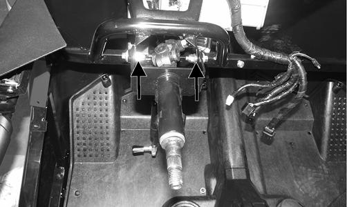
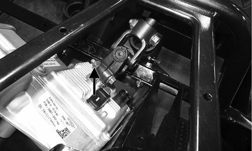
4.Remove upper steering shaft; then remove the cap screws securing the EPS assembly to the frame and steering shaft. Discard lock nut.
WT604A
2.Using the cap screw and a new lock nut, install the upper steering shaft assembly onto the EPS assembly making sure to align the timing mark of the EPS assembly with the opening of the sheering shaft.
Tighten to 25 ft-lb.
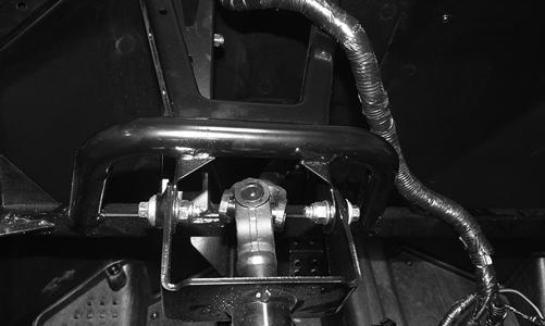
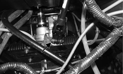
NOTE: Loosening but not removing the cap screw
connecting the steering shaft to the rack and pinion will aid in installing the lower cap screw connecting the lower steering shaft to the EPS assembly. If this step was done, the lower lock nut must be replaced and tightened to 25 ft-lb.
WT609A
WT605
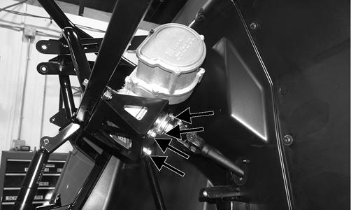
3.Secure the EPS assembly with cap screws and new lock nuts. Tighten to 20 ft-lb.
WT610A
5.Tighten the cap screws securing the EPS assembly to the frame to 35 ft-lb.
6.Install the dash, hood, and steering wheel.
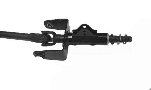
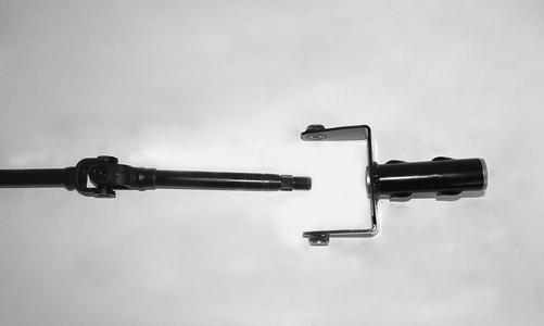
Steering Shaft
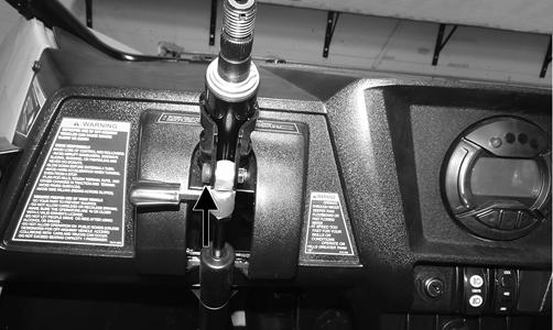
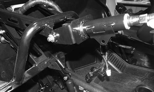
REMOVING 1.Remove the steering wheel and hood; then remove the dash.
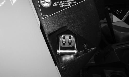
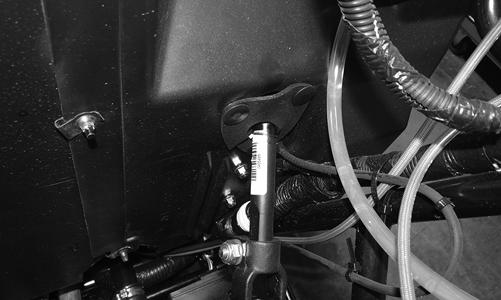
2.Remove and discard the cap screws and lock nuts securing the steering tilt assembly to the frame.
WT607A
4.Install the cap screw and new lock nut securing the lower steering shaft to the EPS assembly.
WT346
3.Remove the push pins securing the rubber boot to the splash panel.

WT604B
WT345A
5.Remove the steering shaft through the splash panel. 6.Remove the snap ring. Account for the two washers.
WT348
2.Using the existing cap screw and new lock nut, secure the steering shaft to the rack and pinion assembly. Tighten to 25 ft-lb. 3.Install the tilt assembly onto the steering shaft and secure it with new cap screws and lock nuts. Tighten to 20 ft-lb.
WT594
7.Slide the tilt assembly out of the steering shaft.
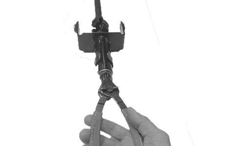
WT351
4.Install the wave washer and washer; then install the snap ring securing the shaft in place.
WT349
NOTE: Only the tilt assembly is a serviceable item.
If the shaft is damaged, it must be replaced.
INSPECTING 1.Check the splines for wear or signs of twisting. 2.Check the U-joints for any clicking or binding. If present, the shaft must be replaced. 3.Check the tilt assembly for cracks or broken welds.
INSTALLING 1.Slide the steering shaft through the splash panel.
With both white lines on the rack and pinion aligned with the gap in the lower knuckle on the steering shaft, slide the steering shaft onto the splines.
WT593
5.Install the rubber boot in place around the steering shaft and secure with the existing push pins.
WT343
6.Install the dash; then install the steering wheel and hood.
Steering Knuckles
REMOVING AND DISASSEMBLING 1.Secure the vehicle on a support stand to elevate the wheel; then remove the wheel. 2.Remove the nut securing the hub. 3.Remove the brake caliper. 4.Remove the hub assembly. 5.Remove the cotter pin from the tie rod end and remove the tie rod end from the knuckle.
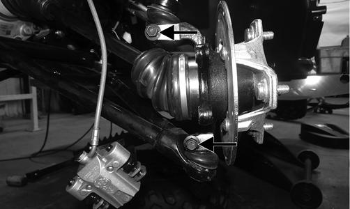
6.Remove the upper cap screw securing the ball joint in the knuckle.
7.Tap the ball joint end out of the knuckle; then slide the axle out of the knuckle.
8.Remove the cap screw securing the lower ball joint to the knuckle and remove the knuckle.
WT329A
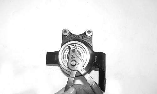
9.Remove the snap ring securing the bearing in the knuckle; then press the bearing out of the knuckle.
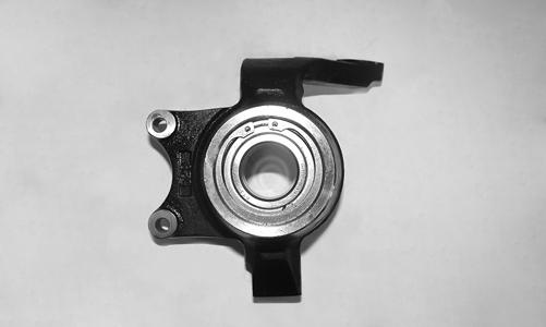
WT326
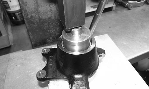
10.Using a suitable press, remove the bearing from the knuckle.
WT327
CLEANING AND INSPECTING 1.Clean all knuckle components. 2.Inspect the bearing for pits, scoring, rusting, or premature wear.
3.Inspect the knuckle for cracks, breaks, or galling of the bearing surface.
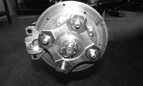
ASSEMBLING AND INSTALLING 1.Using a suitable press and driver, press the bearing into the knuckle until firmly seated; then install the snap ring.
WT327
WT331
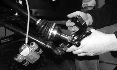
2.Install the knuckle to the lower ball joint and secure with a new “patch-lock” cap screw. Tighten to 35 ft-lb.
3.Slide the axle into the knuckle; then install the upper ball joint and secure with a new “patch-lock” cap screw. Tighten to 35 ft-lb.
WT332
WT329A
4.Install the tie rod end and secure with the nut (coated with red Loctite #263). Tighten to 30 ft-lb; then install a new cotter pin and spread the pin. NOTE: During assembling, new cotter pins should
be installed.
5.Install the hub assembly onto the axle; then secure the hub using the hub nut.
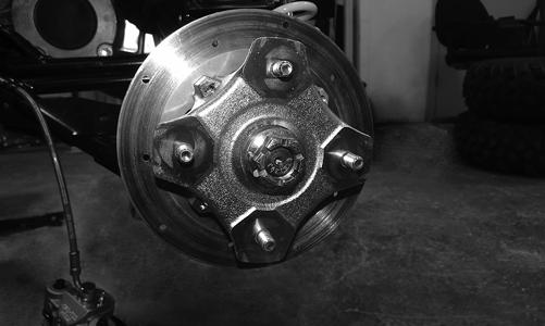
WT451
6.Tighten the hub nut to 200 ft-lb; then install a new cotter pin and spread the pin making sure the side of the pin is flush to the hub nut.
WT275
NOTE: During assembly, new cotter pins should
always be used.
NOTE: If the cotter pin cannot be inserted due to
misalignment of the hole and the slots in the nut, always tighten the nut until it is properly aligned.
7.Secure the brake caliper to the knuckle with the two new “patch-lock” cap screws. Tighten to 20 ft-lb.
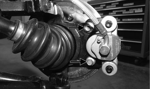
WT287A
8.Install the wheels and tighten the wheel nuts in 20 ft-lb increments to a final torque of 40 ft-lb (steel wheel), 60 ft-lb (aluminum wheel w/black nuts), or 80 ft-lb (aluminum wheel w/chrome nuts). 9.Remove the vehicle from the support stand.
Front Wheel Alignment
NOTE: All measurements and adjustments must be
made with the vehicle unloaded.
NOTE: Make sure the white alignment marks of the
steering rack are aligned.
WT080A
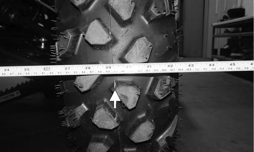
Mark the center-line of the front tires at the front and rear of the tire; then using a tape measure, measure and record the distance between the marks at the front and rear. The front measurement should be 3-6 mm (1/8-1/4 in.) greater than the rear measurement (toe-out).
WT292A
To adjust the wheel alignment, use the following procedure:
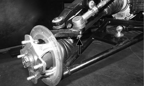
1.Center the steering rack; then using an open-end wrench to hold the tie rod (B), loosen the right-side and left-side jam nuts (A).
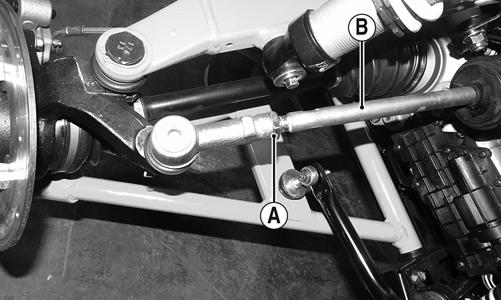
Always use a wrench to hold the tie rod ends when loosening or tightening the jam nuts or damage to the boots could occur.
2.Turn the left-side and right-side tie rods (B) in equal increments to achieve the proper toe-out; then tighten to 25 ft-lb.
Accelerator Pedal
REMOVING Dislodge the yellow nylon bushing of the throttle cable from the actuator arm; then remove two torx-head screws and nuts securing the accelerator pedal assembly to the splash panel and remove the accelerator pedal.
WT099C
WT288A
INSTALLING Align the mounting holes with the holes in the splash panel and secure with the two torx-head screws and new lock nuts; then tighten to 10 ft-lb. Snap the throttle cable bushing into the actuator arm.
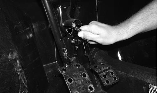
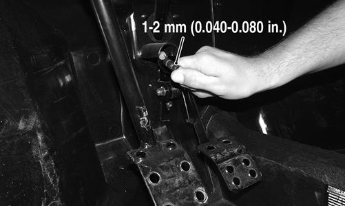
CHECKING CABLE FREE-PLAY 1.Check cable free-play by grasping the cable at the top of the accelerator pedal and lightly pulling rearward to remove slack. Free-play should be 1-2 mm (0.040-0.080 in.).
WT099A
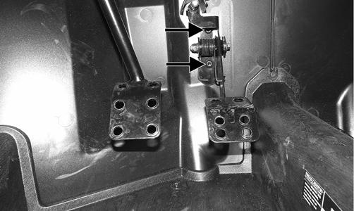
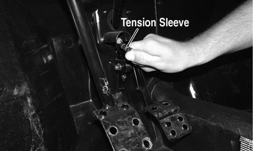
2.Depress the accelerator pedal completely and pull rearward on the cable end. There should not be any free-play and the tension sleeve should not be compressed.
WT099B
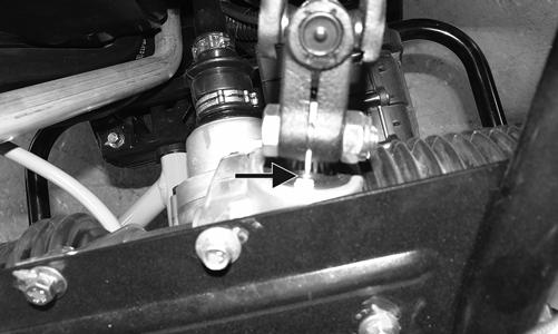
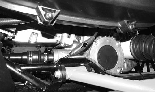
3.To adjust the throttle cable, locate the in-line cable adjuster beneath the clutch cover; then slide the protective sleeve upward from the adjuster.
WT081A
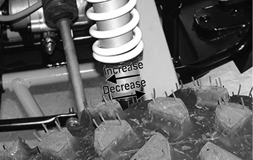
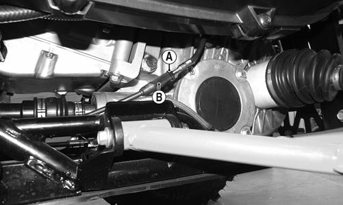
4.Loosen the jam nut (A) and turn the adjuster (B) clockwise to increase free-play or counterclockwise to decrease. 5.Tighten the jam nut securely and slide the protective sleeve over the adjuster making sure the sleeves overlap over the seal.
Shift Lever
REMOVING 1.Remove the seats, shifter knob, and center console.
WT281B
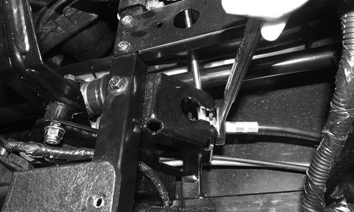
2.Remove the cap screw from the shift cable pivot bolt (A), remove the axle bolt (B), and account for plastic inserts (C).
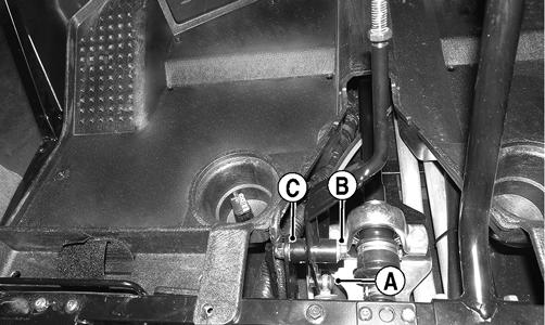
WT296A
3.Remove the shift lever.
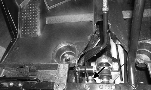
INSTALLING 1.Connect the shift cable to the shift arm with the pivot bolt and new lock nut. Tighten to 8 ft-lb. 2.Place the shift lever into position and secure with the axle bolt, plastic inserts, and new lock nut. Tighten to 20 ft-lb.
3.Install the center console, shifter knob, and seats.
Make sure the seats lock securely in place.
Shift Cable
REMOVING 1.Remove the seats and center console.
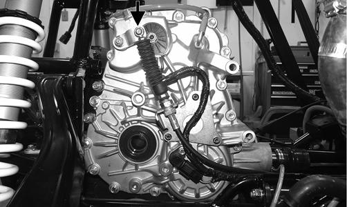
2.Remove the E-clip securing the shift cable to the transaxle.
WT439B
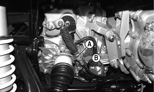
3.While holding the nut (B), loosen the jam nut (A) and remove the shift cable from the transaxle.
WT225B
4.Remove the cap screw and lock nut securing the shift cable to the shift arm. Discard the nut.
WT296B
5.Cut the plastic wire ties securing the cable to frame noting their locations for installing. 6.Loosen the jam nut (A) securing the shift cable on the shifter bracket and remove the shift cable noting the cable location for installing.
INSTALLING 1.Install the new shift cable in place noting the routing from removing. Secure to the transaxle with the
E-clip and jam nut. Finger-tighten the jam nut at this point. 2.Install the shift cable end to the shifter bracket and secure with the cap screw, new lock nut, and jam nuts.
3.Install any necessary cable ties as marked during removing; then adjust the shift cable (see ADJUST-
ING in this sub-section). After cable is properly adjusted, tighten the jam nuts to 20 ft-lb. 4.Install the center console and seats. Make sure the seats lock securely in place.
ADJUSTING 1.Remove the seats, shifter knob, engine access panel, and center console.
WT281B
2.With the transmission in neutral, loosen the jam nut (A) and adjust the cable until there is a small amount of free-play in the shift lever moving forward and backward while still in neutral.
WT276A
3.Once the proper adjustment is achieved, tighten the jam nut to 20 ft-lb.
WT342
NOTE: After the jam nuts are secure, check the
shift cable again for proper adjustment.
4.Install the center console and engine access panel. 5.Install the shifter knob and tighten the jam nut to 12 ft-lb.
WT274A
6.Install the seats. Make sure the seats lock securely in place
LCD Gauge
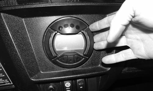
REMOVING/INSTALLING To remove the gauge, pull out on one side of it; then disconnect the multi-pin connector and remove the gauge.
WT339
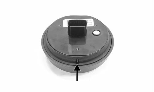
To install the gauge, connect the multi-pin connector and press the gauge into the dash. NOTE: Ensure the rubber mounting ring is ori-
ented correctly on the tab and seats fully through the dash.
WT601A
Muffler
REMOVING 1.Remove the two exhaust springs at the muffler/exhaust pipe juncture.
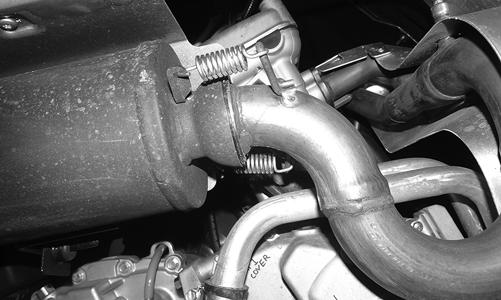
WT295
! WARNING
The heat deflector under the right-rear fender has sharp edges and can cause serious injury if care is not taken. 2.Slide the muffler assembly clear of the holder pins.
Account for the exhaust gasket.
INSPECTING 1.Inspect muffler externally for cracks, holes, and dents.
2.Inspect the muffler internally by shaking the muffler back and forth and listening for rattles or loose debris inside the muffler.
NOTE: For additional details on cleaning the muf-
fler/spark arrester, see Periodic Maintenance/Tune-Up.
INSTALLING 1.With the gasket in place, place the muffler onto the holder pins and slide into position.
WT293A
NOTE: Starting with the upper rear pin will aid in
installing.
2.Secure the muffler to the exhaust pipe with the two exhaust springs.
Cargo Box
REMOVING 1.Remove the seats and rear fenders.
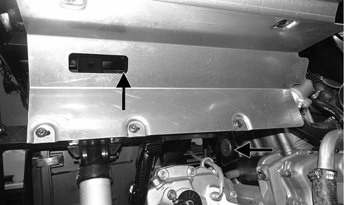
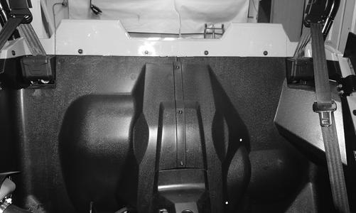
2.Remove the LED taillight assembly. 3.Remove the fasteners securing the upper rear body panel to the splash guard.
WT229A
4.Remove the fasteners securing the cargo box.
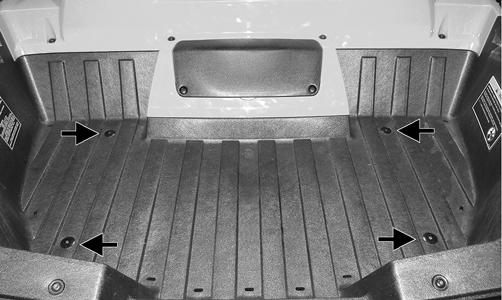
WT234A
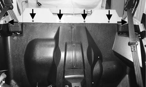
5.Remove the fasteners securing the upper rear body panel to the cargo box.

WT230A
WT231A
INSTALLING 1.Secure the upper rear body panel to the cargo box and tighten the cap screws to 15 in.-lb. 2.Install the cargo box into position so the upper body panel is over the top of splash guard; then tighten the cap screws to 5 ft-lb.
WT229
3.Secure the cargo box with self tapping screws and tighten to 5 ft-lb. 4.Install the LED taillight assembly. 5.Install the rear fenders; then install the seats making sure they lock securely in place.
Seats
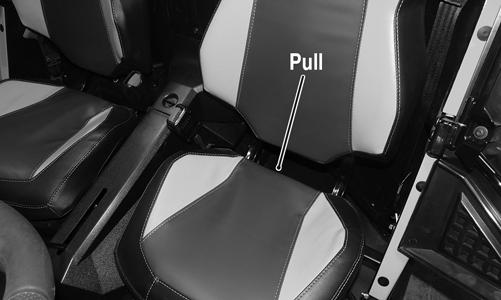
REMOVING/INSTALLING 1.To remove a seat, pull the seat lock lever up. Raise the rear of the seat and tilt it forward.
WT003A
2.To install a seat, slide the front of the seat into the seat retainers and push down firmly on the rear of seat. The seat should automatically lock into position.
Doors
CHECKING/ADJUSTING NOTE: The ROPS must be fully installed whenever
adjusting the doors in any way.
Inspect the doors for broken or bent tubes, hinges, or latches. Make sure the latches engage and lock securely; if not, use the following instructions. 1.Open the door to ensure it swings freely. If not, loosen the two top fasteners and adjust door as necessary until it swings freely. Tighten the fasteners securely.
WT110A
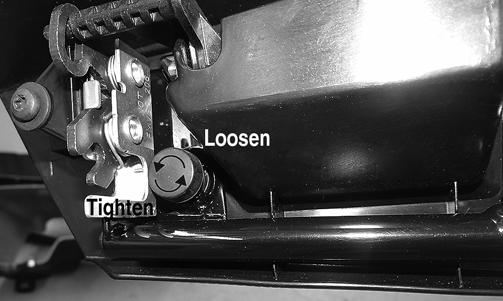
2.Close the door to ensure it latches securely. If not, loosen the fasteners and adjust the latch up or down until the door latches securely. Tighten the fasteners securely. 3.With the door closed, ensure the rubber bumper contacts the latch. To adjust, turn the bumper in (loosen) or out (tighten).

WT108A
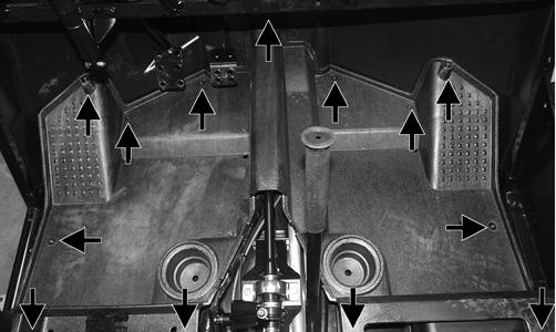
Floor
REMOVING 1.Remove the seats, engine access panel, and center console.
2.Remove the fasteners securing the floor to the frame.
WT344A
CLEANING AND INSPECTING 1. Clean any debris from underneath the floor. 2. Inspect the floor for any cracks or holes.
INSTALLING 1.Install the floor into position and secure it with the existing cap screws. Tighten securely. 2.Install the center console, engine access panel, and seats. Make sure the seats lock securely in place.
Troubleshooting
Problem: Handling too heavy or stiff Condition Remedy
1. Front wheel alignment incorrect 1.Adjust alignment 2. Lubrication inadequate 2.Lubricate appropriate components 3. Tire inflation pressure incorrect 3.Adjust pressure 4. Tie rod ends seizing 4.Replace tie rod ends 5. Linkage connections seizing 5.Repair - replace connections 6. EPS malfunction 6.Troubleshoot - replace EPS
Problem: Steering oscillation Condition Remedy
1. Tires inflated unequally 1.Adjust pressure 2. Wheel(s) wobbly 2.Replace wheel(s) 3. Wheel hub cap screw(s) loose - missing 3.Tighten - replace cap screws 4. Wheel hub bearing worn - damaged 4.Replace bearing 5. Tie rod ends worn - loose 5.Replace - tighten tie rod ends 6. Tires defective - incorrect 6.Replace tires 7. A-arm bushings damaged 7.Replace bushings 8. Bolts - nuts (frame) loose 8.Tighten bolts - nuts
Problem: Steering pulling to one side Condition Remedy
1. Tires inflated unequally 1.Adjust pressure 2. Front wheel alignment incorrect 2.Adjust alignment 3. Wheel hub bearings worn - broken 3.Replace bearings 4. Frame distorted 4.Repair - replace frame 5. Shock absorber defective 5.Replace shock absorber
Problem: Steering impaired Condition Remedy
1. Tire pressure too high 1.Adjust pressure 2. Steering linkage connections worn 2.Replace connections 3. Cap screws (suspension system) loose 3.Tighten cap screws
Problem: Tire wear rapid or uneven Condition Remedy
1. Wheel hub bearings worn - loose 1.Replace bearings 2. Front wheel alignment incorrect 2.Adjust alignment
Problem: Steering noise Condition Remedy
1. Caps screws - nuts loose 1.Tighten cap screws - nuts 2. Wheel hub bearings broken - damaged 2.Replace bearings 3. Lubrication inadequate 3.Lubricate appropriate components
Problem: Rear wheel oscillation Condition Remedy
1. Rear wheel hub bearings worn - loose 1.Replace bearings 2. Tires defective - incorrect 2.Replace tires 3. Wheel rim distorted 3.Replace wheel 4. Wheel hub cap screws loose 4.Tighten cap screws 5. Rear suspension lateral link bushing worn 5.Replace bushing 6. Trailing arm bushings worn 6.Replace bushings or link 7. Rear suspension lateral link loose 7.Tighten nut or replace