15 minute read
Fuel/Lubrication/Cooling

! WARNING
Whenever the gasline hoses are removed (other than for pressure testing), the battery must be disconnected to prevent inadvertent activation of the electric fuel pump. ! WARNING
Advertisement
Whenever any maintenance or inspection is performed on the fuel system during which there may be fuel leakage, there should be no welding, smoking, open flames, etc., in the area.
SPECIAL TOOLS A number of special tools must be available to the technician when performing service procedures in this section. Refer to the current Special Tools Catalog for the appropriate tool description. NOTE: When indicated for use, each special tool
will be identified by its specific name, as shown in the chart below, and capitalized.
NOTE: Special tools are available from the Arctic
Cat Service Department.
Description p/n
Oil Pressure Test Kit 0644-495 Tachometer 0644-275
TROUBLESHOOTING 1.Verify that the electric fuel pump is operating by listening for a “whirring” sound for approximately three seconds after the ignition switch is turned to the
ON position. If no sound can be heard, see FUEL
PUMP/FUEL LEVEL SENSOR in this section.
2.Check for a diagnostic trouble code (DTC) on the
LCD. If the light is flashing, see EFI Diagnostic System in Electrical System. 3.Make sure there is sufficient, clean gas in the gas tank.
4.Verify that the battery is sufficiently charged to crank the engine over at normal speed. 5.Check the air filter housing and air filter for contamination. Clean or replace as necessary (see Periodic
Maintenance/Tune-Up).
Throttle Body
REMOVING 1.Turn the ignition switch to the OFF position; then remove the ignition key. 2.Remove the rear body panels and the cargo box. 3.Remove the clamp on the engine intake tube and loosen the air intake clamp.
! WARNING
Do not turn the ignition switch to the ON position with the hoses removed. Gasoline will be pumped by the electric fuel pump causing a safety hazard.
WT314A
NOTE: Removing the intake boot with the air filter
housing will aid in installation.
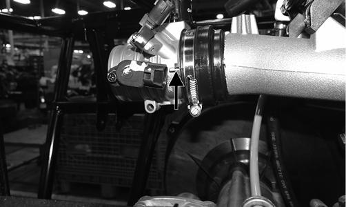
4.Loosen the throttle body clamp.
WT316A
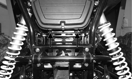
5.Remove and discard the “patch lock” cap screws securing the air intake housing bracket to the intake manifold.
WT313C
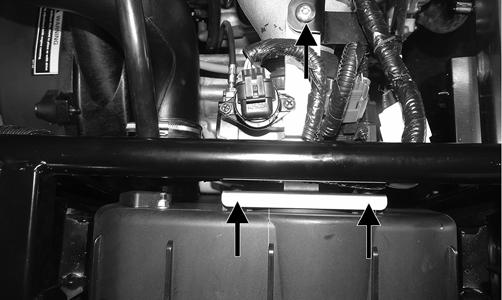
6.Remove and retain the lower cap screws and grommets.
WT315A
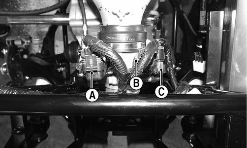
7.Remove the air filter housing. 8.Remove the ISC connector (A), MAP/IAT connector (B), and TPS connector (C).
WT397A
9.Remove the throttle arm cover; then disconnect the throttle cable.
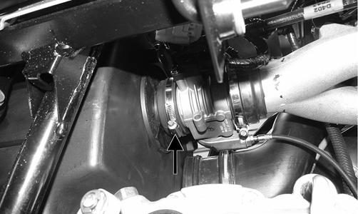
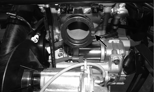
10.Loosen the clamp securing the throttle body to the intake manifold; then remove the throttle body.
INSTALLING 1.Connect the throttle cable to the throttle arm; then install the throttle cable housing cover to the throttle body. Tighten to 8 ft-lb. 2.Make sure the alignment tab on the throttle body aligns with the slot in the intake boot and install the throttle body fully into the boot. Secure with worm clamps and tighten securely.
WT567A WT566A
3.Connect the ISC connector (A), MAP/IAT connector (B), and the TPS connector (C).
WT397A
4.Install the air filter housing in place and install the outlet boot of the housing over the throttle body.
Secure with the clamp. 5.With the existing cap screws, grommets, and spacers, secure the lower portion of air filter housing to the frame. Tighten to 5 ft-lb.
WT315A
6.Using new “patch lock” cap screws, secure the air filter housing mount to the intake manifold (A).
Tighten to 5 ft-lb; then secure the mount to the air filter housing (B). Tighten to 36 in.-lb. 7.Install the engine intake tube and air intake to the air filter housing and secure with the clamps.
WT314A
8.Install the cargo box and rear body panels. NOTE: If the throttle body, ECM, TPS, or ISC are
replaced, the EFI system must be synchronized. Use the following procedure.
1.With the key off, depress the accelerator pedal to
Wide Open Throttle (WOT). 2.Place the ignition key in the ON position and wait for 10 seconds.
3.Release the accelerator pedal, and wait an additional 10 seconds.
4.Turn the key to the OFF position and allow the gauge to shut off.
Gas Tank
! WARNING
Whenever any maintenance or inspection is made on the fuel system during which there may be fuel leakage, there should be no welding, smoking, open flames, etc., in the area.
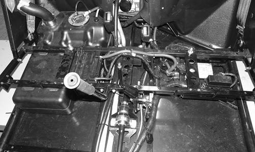
REMOVING 1.Remove the seats, engine access panel, and center console.
2.Remove the floor and side panels. 3.Remove the battery access panel and battery. 4.Remove the right rear side panel and right rear fender.
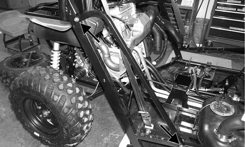
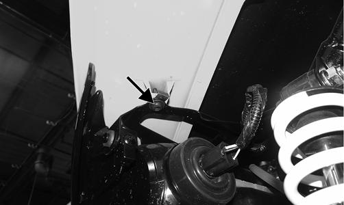
5.Remove the cap screws and discard the lock nuts securing the right side frame tube.
WT365A
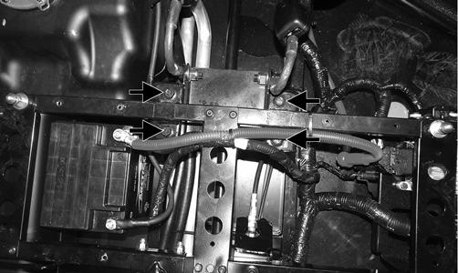
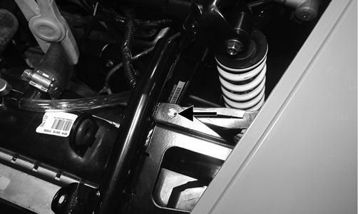
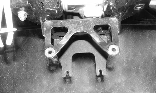
6.Remove the four cap screws securing the seat base to the frame.
WT359A
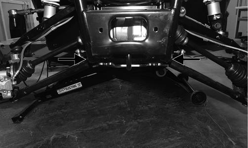
7.Remove the remaining cap screws securing the frame tubes to the frame. Remove both frame tubes.
WT360
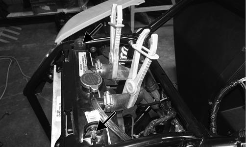
8.Slide the gas tank slightly forward and disconnect the gasline hose, vent hose, and fuel pump; then remove the gas tank.
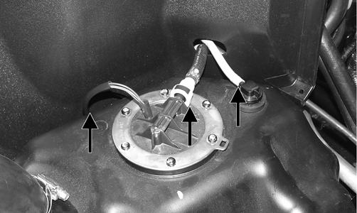
INSTALLING 1.Place the gas tank into position; then connect the gasline hose, vent hose, and fuel pump. 2.Place the two frame tubes into position and secure (but do not tighten) with new “patch-lock” cap screws.
3.Install the remaining fasteners; then tighten all fasteners securely. 4.Using new lock nuts, install the right side frame tube and tighten securely. 5.Place the battery into position and connect the battery cables (negative cable first). Tighten the cables securely. 6.Install the floor and battery access panel. 7.Install the right rear side panel and the right rear fender.
8.Install the center console, engine access panel, and seats.
Gas/Vent Hoses
Replace the gas hose every two years. Damage from aging may not always be visible. Do not bend or obstruct the routing of the vent hoses. Make certain the vent hoses are securely connected and the opposite ends are always open.
Oil Filter/Oil Pump
NOTE: Whenever internal engine components wear
excessively or break and whenever oil is contaminated, the oil pump should be replaced.
TESTING OIL PUMP PRESSURE NOTE: The engine must be warmed up to operating
temperature (cooling fan cycling) for this test.
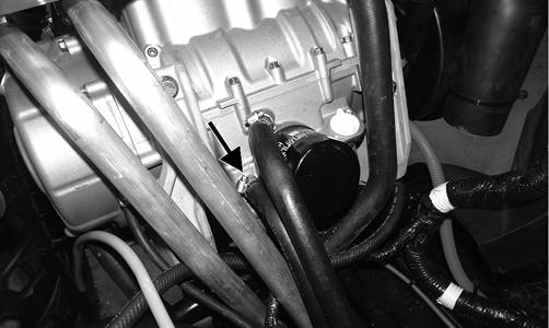
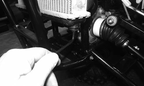
1.Remove the oil hose from the fitting nearest the oil filter base.
WT568A
2.Using a suitable “T” fitting, connect Oil Pressure
Test Kit to the lower oil fitting and hose. Tighten all clamps securely. NOTE: Some oil seepage may occur when installing
the oil pressure gauge. Wipe up oil residue with a cloth.
3.Place the transmission in neutral and start the engine.
Set the speedometer/tachometer to RPM. 4.With the engine running at 3000 RPM and the coolant at room temperature (approximately 70° F), the pressure gauge must show 6.68-8.44 kg/cm2 (95-120 psi). 5.With the engine running at 3000 RPM and the coolant at approximately 195° F (cooling fan cycling), the pressure gauge must show 5.27-6.68 kg/cm2 (75-95 psi). 6.Remove the test kit from the vehicle and install the oil hose. Tighten the clamps securely. NOTE: If oil pressure is lower than specified, check
for an oil leak, clogged oil filter, or defective oil pump.
NOTE: If oil pressure is higher than specified, check
for too heavy engine oil weight (see General Information/Foreword), clogged oil passage, or improper installation or type of the oil filter.
REMOVING/DISASSEMBLING 1.Remove the oil pump from the engine (see Bottom-Side Components in Engine). 2.Remove oil pump components from crankcase.
CLEANING AND INSPECTING 1.Clean all oil-pump components. 2.Inspect the rotors for scoring and gouges. 3.Inspect the driveshaft and driven sprocket for damage. 4.Inspect the crankcase for scoring, cracks, or damage.
ASSEMBLING/INSTALLING 1.Place the rotors into the crankcase making sure the dowel pin is in the groove of the rotor. 2.Place the cover onto the crankcase.
3.Secure the pump with the two cap screws coated with blue Loctite #243. Tighten to 8 ft-lb.
Oil Cooler
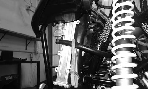
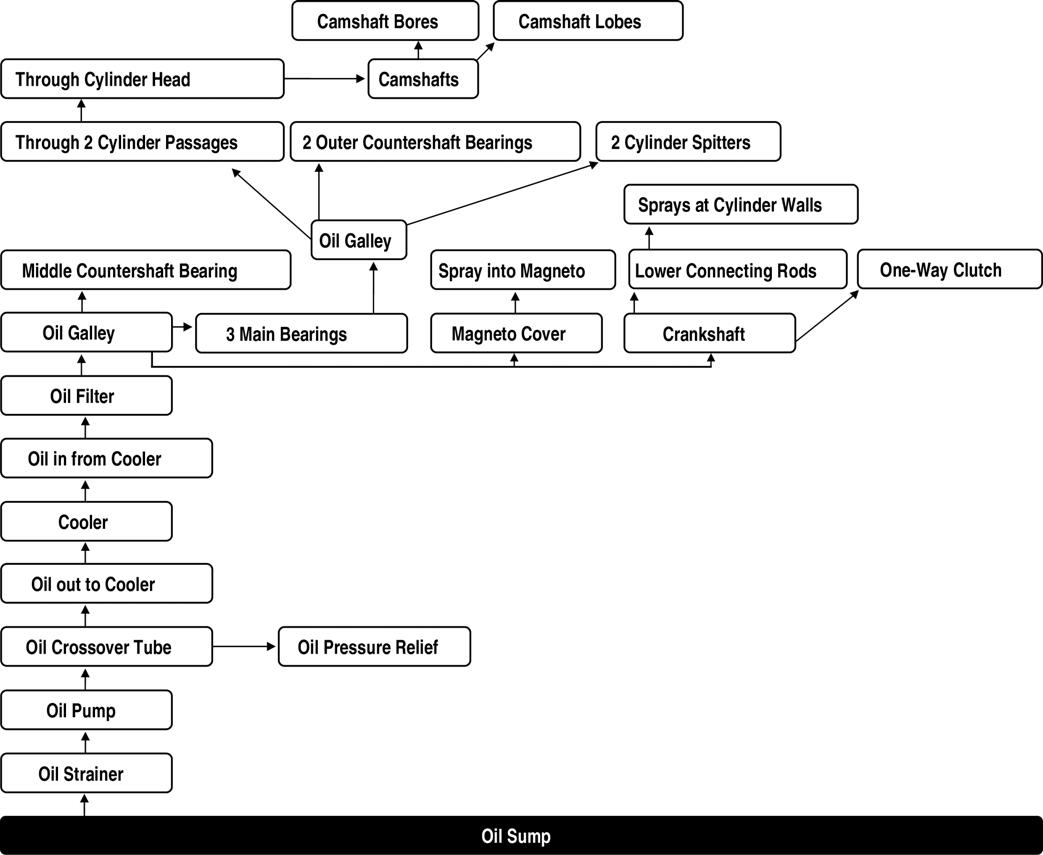
REMOVING 1.Remove the hood and front bumper. 2.Using appropriate clamps, close off both oil hoses. 3.Loosen the clamps securing the oil hoses to the oil cooler; then place an absorbent towel under the connection and remove the hoses.
WT455
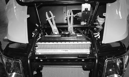
4.Remove the cap screws securing the oil cooler to the radiator and remove the oil cooler.
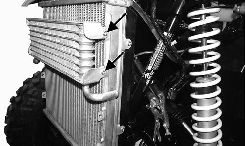
WT549A
CLEANING AND INSPECTING 1.Prior to washing, inspect the oil cooler for signs of leaks, oily dirt build-up, or plugged cooling fins. 2.Wash the cooling fins using a garden hose and hot, soapy water and a soft brush. 3.Inspect all mounting brackets and the oil inlet and outlet for cracks or bends.
INSTALLING 1.Place the oil cooler into position and secure with the existing hardware. Tighten securely. 2.Connect the oil hoses and secure with the hose clamps. Tighten securely. 3.Remove the oil hose close-off clamps. 4.Start the engine and allow it to run for approximately two minutes. Verify engine oil level and add oil as required. 5.Install the hood and front bumper.
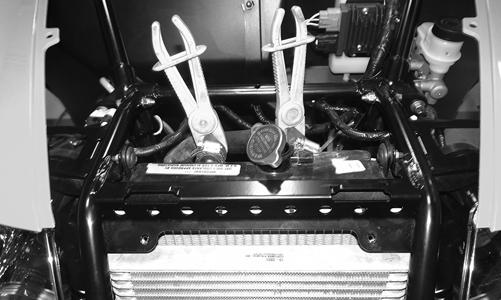
Oil Flow Chart
oil_flow_wt
Liquid Cooling System
When filling the cooling system, use premixed Arctic Cat Antifreeze. While the cooling system is being filled, air pockets may develop; therefore, open the bleed screw on the thermostat housing to allow air to bleed from the cooling system. When clear coolant (no bubbles) is present, tighten the bleed screw securely; then fill the cooling system to the bottom of the stand pipe in the radiator neck. Run the engine for five minutes after the initial fill, shut the engine off, and then “top-off” the cooling system to the bottom of the stand pipe in the radiator neck.
CAUTION
After operating the vehicle for the initial 5-10 minutes, stop the engine, allow the engine to cool down, and check the coolant level. Add coolant as necessary.
Radiator
REMOVING 1. Remove the hood and grille. 2.Using appropriate clamps, close off the coolant hoses to the radiator and the oil hoses to the oil cooler.
WT455
WT459
3.Using an appropriate Allen wrench, remove the drain plug from the bottom of the radiator and drain the coolant into a suitable pan. Account for an O-ring on the drain plug.
WT452
NOTE: Opening the radiator cap will aid in drain-
ing the radiator.
4.Disconnect the headlights.

WT463
5.Remove the cap screws securing each front fender to the frame.
WT453A
6.Remove the cap screws securing the radiator to the frame and disconnect the overflow bottle hose from the top of the radiator.
WT456A
7.Using a suitable prying tool, pry the clips out from between the wiring harness and the frame; then push the clips downward to remove them from the frame.
WT454A
8.Remove the cap screws securing the front bumper to the frame. Discard the lock nuts.

WT459A
WT460A
9.Pull the bumper away from the vehicle.
WT461
10.Disconnect the radiator fan and remove the radiator/oil cooler from the vehicle. Drain the remaining coolant into a suitable container.
WT458
NOTE: If the radiator will be replaced, transfer the
cooling fan and oil cooler to the new radiator.
INSTALLING 1.Place the assembled radiator studs into the mounting holes on the radiator bracket. Connect the coolant hoses and oil hoses; then secure them with the worm hose clamps. Remove the close-off clamps.
WT464
2.Connect the fan motor connector, and connect the overflow bottle hose to the radiator. Install the drain plug with O-ring and tighten securely. 3.Install the bumper frame in place and, using the existing cap screws and new lock nuts, finger-tighten only at this time.
WT459A
4.Install the lower bumper cap screws and tighten the upper and lower bumper cap screws to 20 ft-lb.
WT460A
5.Install the cap screws and nuts securing the radiator to the frame. Tighten to 8 ft-lb. 6.Install the cap screws securing the front fenders to the frame. Tighten securely and plug in the headlights. 7.Using the existing cap screws, secure the grille and tighten securely. 8.Fill the radiator with the proper mixture of coolant until there are no more air bubbles present and the coolant level is above the cooling fins inside the radiator. Tighten the radiator cap. 9.Install the hood and tighten the two quarter-turn fasteners.
Thermostat
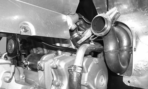
REMOVING NOTE: The thermostat is located on the right side
in a housing in-line with the coolant hose behind the muffler.
NOTE: Removing the muffler will aid in removing. 1.Drain a couple of cups of coolant from the water pump. 2.Clamp off the coolant hoses and place an absorbent towel under the thermostat.
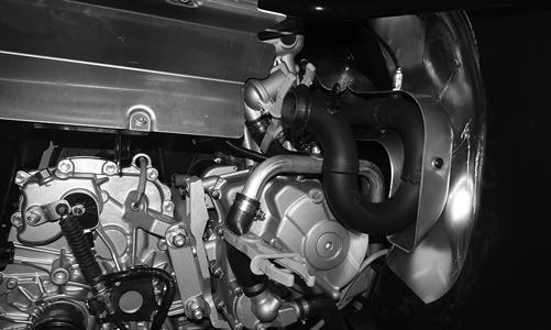
WT535
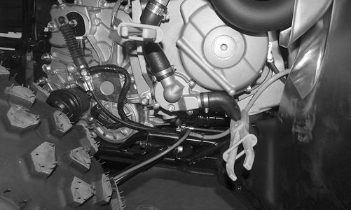
3.Remove the hose from the bottom of the thermostat housing and push out of the way.
WT547
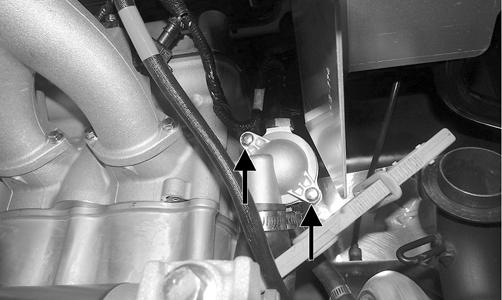
4.Remove the two cap screws securing the thermostat housing together. Remove the thermostat.
WT534A
INSPECTING 1.Inspect the thermostat for corrosion or spring damage. 2.Using the following procedure, inspect the thermostat for proper operation. A.Suspend the thermostat in a container filled with water.
B.Heat the water and monitor the temperature with a thermometer.
C.The thermostat should start to open at 80.0-84.0° C (176-183° F). D.If the thermostat does not open, it must be replaced. 3.Inspect all coolant hoses, connections, and clamps for deterioration, cracks, and wear. NOTE: All coolant hoses and clamps should be
replaced every four years or 4000 miles.
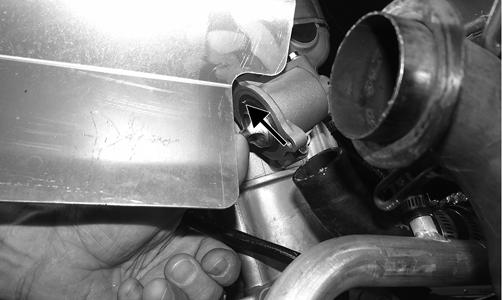
INSTALLING 1.Install the thermostat into the thermostat housing so the bleeder valve is facing up.
WT546A
2.Install the thermostat cover; then making sure the thermostat is properly seated, tighten the cap screws to 5 ft-lb.
3.Install the hose on the bottom of thermostat housing and secure with the hose clamp. 4.Remove the close-off clamps; then install the muffler and secure with the springs. 5.Add the recommended anti-freeze as required; then bleed the cooling system and check for leaks.
Fan
REMOVING 1.Remove the radiator.
2.Remove the fan assembly from the radiator.
INSTALLING 1.Position the fan assembly on the radiator; then secure with existing hardware. NOTE: The fan wiring must be directed downward. 2.Install the radiator.
Water Pump
NOTE: The water pump is a non-serviceable com-
ponent. It must be replaced as an assembly.
REMOVING NOTE: If the engine is still in the vehicle, drain the
oil and remove the muffler, exhaust pipe, and right-side inner splash panel.
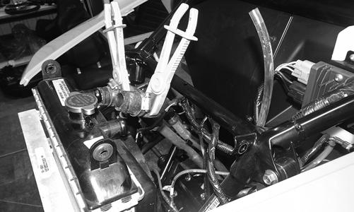
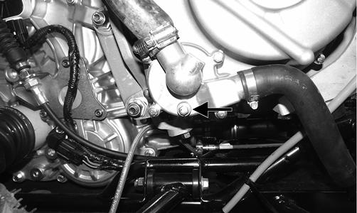
1.Using appropriate clamps, close off the coolant hose before and after the water pump.
WT533
2.Drain the coolant from the pump and remove the hoses from the water pump.
WT399A
3.Remove the cap screws securing the magneto cover to the engine. 4.Remove the cap screws securing the impeller cover to the magneto cover. Account for an O-ring and two dowel pins.
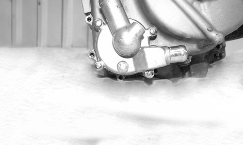
WT578
5.Remove the E-clip and washer from the impeller shaft and remove the impeller from the case half.
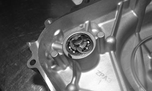
WT571
6.Using an appropriate press, remove the two bearings.
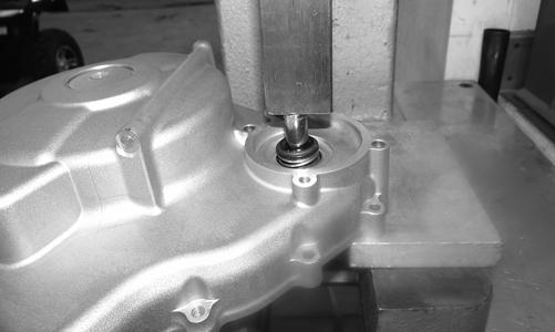
WT572
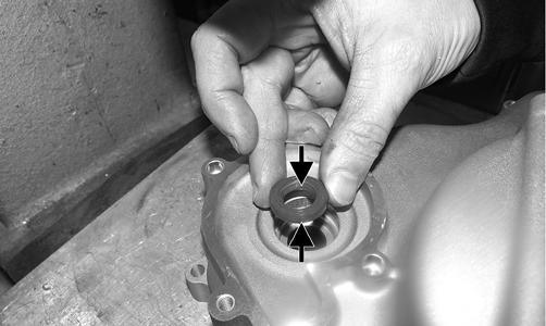
7.Using an appropriate press, remove the rubber seal and mechanical seal as an assembly.
WT570
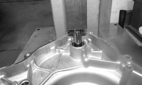
INSTALLING 1.Apply grease to the inside and outside of the seal; then press in the rubber seal.
WT576A
CAUTION
Only apply pressure to the center race of the seal while installing to avoid damaging the seal.
2.Using a section of 1” pipe, press in the mechanical seal.
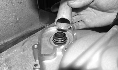
WT575
CAUTION
It is critical while pressing the seal into position to press on the outer diameter of the seal to avoid damaging the mechanical seal.
3.Individually press in the bearings.
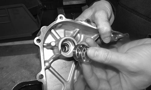
WT573
4.Install the impeller in place and secure with a washer and E-clip. 5.Install the magneto cover and secure with the cap screws. Tighten the screws to 11 ft-lb. 6.Install the impeller cover and secure with the cap screws. Tighten the screws to 11 ft-lb.
NOTE: The two longer cap screws go in the dowel
pin locations.
7.Install the coolant hoses; then add the appropriate mixture of coolant until the appropriate level is reached (seeFuel/Lubrication/Cooling). 8.If removed, install the muffler, exhaust pipe, and right-side inner splash panel. 9.If drained, add the appropriate engine oil until the correct level has been reached.
Troubleshooting
Problem: Starting impaired Condition Remedy
1. Gas contaminated 1.Drain gas tank and fill with clean gas 2. Throttle cable too tight 2.Adjust throttle cable and synchronize EFI system (see Electrical System)
Problem: Idling or low speed impaired Condition Remedy
1. TPS out of adjustment 1.Adjust TPS (out of warranty) or replace the throttle body (under warranty) 2. Throttle cable too tight 2.Adjust throttle cable and synchronize EFI system (see Electrical System) 3. Throttle body dirty 3.Clean throttle body
Problem: Medium or high speed impaired Condition Remedy
1. High RPM “cut out” against RPM limiter 1.Decrease RPM speed