26 minute read
Electrical System

This section has been organized into sub-sections which show procedures for the complete servicing of the Arctic Cat ATV electrical system. The electrical connections should be checked periodically for proper function. In case of an electrical failure, check fuses, connections (for tightness, corrosion, damage), and/or bulbs. SPECIAL TOOLS A number of special tools must be available to the technician when performing service procedures in this section. Refer to the current Special Tools Catalog for the appropriate tool description.
Description
Fluke Model 77 Multimeter p/n
0644-559
MaxiClips
0744-041 Peak Voltage Reading Adapter 0644-307 Tachometer 0644-275 Timing Light 0644-296
NOTE: Special tools are available from the Arctic Cat Service Parts Department. TESTING ELECTRICAL COMPONENTS All of the electrical tests should be made using the Fluke Model 77 Multimeter and when testing peak voltage, the Peak Voltage Reading Adapter must be used. If any other type of meter is used, readings may vary due to internal circuitry. When troubleshooting a specific component, always verify first that the fuse(s) are good, that the bulb(s) are good, that the connections are clean and tight, that the battery is fully charged, and that all appropriate switches are activated.
NOTE: For absolute accuracy, all tests should be made at room temperature of approximately 68° F.
RPM Limiter
NOTE: The ATV is equipped with a CDI unit that retards ignition timing when maximum RPM is approached. When the RPM limiter is activated, it could be misinterpreted as a high-speed misfire.
Switches
Each time the ATV is used, switches should be checked for proper operation. Use the following list for reference.
A.Ignition switch — engine will start.
B.Emergency stop switch — engine will stop. C.Reverse switch — reverse indicator light will illuminate. D.Hi/Lo switch — headlight high beam or low beam will illuminate. E.Brake switches — rear brakelight will illuminate.
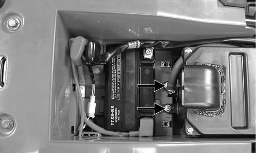
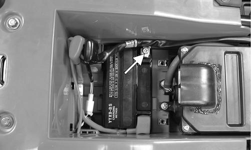
Battery
The battery is located under the seat. After being in service, batteries require regular cleaning and recharging in order to deliver peak performance and maximum service life. The following procedure is recommended for cleaning and maintaining a sealed battery. Always read and follow instructions provided with battery chargers and battery products. NOTE: Refer to all warnings and cautions provided with the battery or battery maintainer/charger. Loss of battery charge may be caused by ambient temperature, ignition OFF current draw, corroded terminals, self discharge, frequent start/stops, and short engine run times. Frequent winch usage, snowplowing, extended low RPM operation, short trips, and high amperage accessory usage are also reasons for battery discharge. Maintenance Charging NOTE: Arctic Cat recommends the use of the CTEK Multi US 800 or the CTEK Multi US 3300 for battery maintenance charging. Maintenance charging is required on all batteries not used for more than two weeks or as required by battery drain.
800E 1. When charging a battery in the vehicle, be sure the ignition switch is in the OFF position. 2. Clean the battery terminals with a solution of baking soda and water.
NOTE: The sealing strip should NOT be removed and NO fluid should be added.
3. Be sure the charger and battery are in a well-ventilated area. Be sure the charger is unplugged from the 110-volt electrical outlet.
4. Connect the red terminal lead from the charger to the positive terminal of the battery; then connect the black terminal lead of the charger to the negative terminal of the battery. NOTE: Optional battery charging adapters are available from your authorized Arctic Cat dealer to connect directly to your vehicle from the recommended chargers to simplify the maintenance charging process. Check with your authorized Arctic Cat dealer for proper installation of these charging adapter connectors.
5. Plug the battery charger into a 110-volt electrical outlet. 6. If using the CTEK Multi US 800, there are no further buttons to push. If using the CTEK Multi US 3300, press the Mode button (A) at the left of the charger until the Maintenance Charge Icon (B) at the bottom illuminates. The Normal Charge Indicator (C) should illuminate on the upper portion of the battery charger. NOTE: The maintainer/charger will charge the battery to 95% capacity at which time the Maintenance Charge Indicator (D) will illuminate and the maintainer/charger will change to pulse/float maintenance. If the battery falls below 12.9 DC volts, the charger will automatically start again at the first step of the charge sequence.
3300A
NOTE: Not using a battery charger with the proper float maintenance will damage the battery if connected over extended periods. Charging
NOTE: Arctic Cat recommends the use of the CTEK Multi US 800 or the CTEK Multi US 3300 for battery maintenance charging. 1. Be sure the battery and terminals have been cleaned with a baking soda and water solution. NOTE: The sealing strip should NOT be removed and NO fluid should be added.
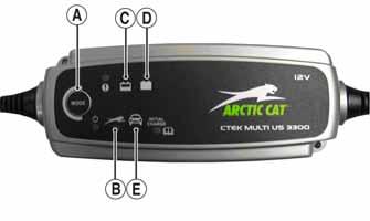
2. Be sure the charger and battery are in a well-ventilated area. Be sure the charger is unplugged from the 110-volt electrical outlet. 3. Connect the red terminal lead from the charger to the positive terminal of the battery; then connect the black terminal lead of the charger to the negative terminal of the battery. 4. Plug the charger into a 110-volt electrical outlet. 5. By pushing the Mode button (A) on the left side of the charger, select the Normal Charge Icon (E). The
Normal Charge Indicator (C) should illuminate on the upper left portion of the charger. 6. The battery will charge to 95% of its capacity at which time the Maintenance Charge Indicator (D) will illuminate.
NOTE: For optimal charge and performance, leave the charger connected to the battery for a minimum 1 hour after the Maintenance Charge Indicator (D) illuminates. If the battery becomes hot to the touch, stop charging. Resume after it has cooled. 7. Once the battery has reached full charge, unplug the charger from the 110-volt electrical outlet. NOTE: If, after charging, the battery does not perform to operator expectations, bring the battery to an authorized Arctic Cat dealer for further troubleshooting.
Brakelight Switch
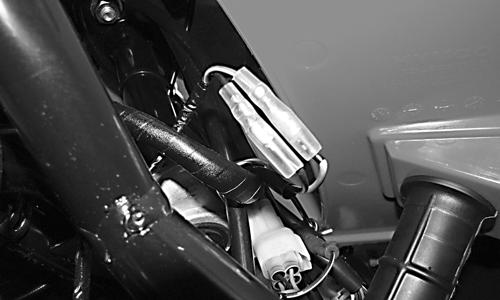
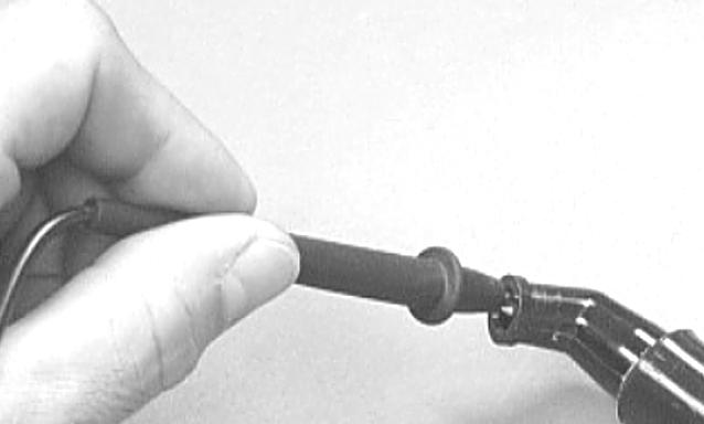
FRONT BRAKE The switch pigtail connects to the main wiring harness with two separate bullet-type connectors directly in front of the upper steering shaft bearing.
TR228
NOTE: The ignition switch must be in the ON position.
Voltage (Wiring Harness Side) 1. Set the meter selector to the DC Voltage position. 2. Connect the red tester to the black wire; then connect the black tester lead to ground. 3. The meter must show battery voltage. NOTE: If the meter shows no battery voltage, troubleshoot the battery, fuse, switch, or the main wiring harness.
NOTE: If the meter shows battery voltage, the main wiring harness is good; proceed to test the switch/ component, the connector, and the switch wiring harness for resistance.
Resistance (Switch Connector) CAUTION
Always disconnect the battery when performing resistance tests to avoid damaging the multimeter. 1. Set the meter selector to the OHMS position. 2. Connect the red tester lead to the black wire; then connect the black tester lead to the green/yellow wire. 3. When the brake lever is compressed, the meter must show less than 1 ohm.
NOTE: If the meter shows more than 1 ohm of resistance, replace the switch. REAR BRAKE The switch has spade-type connectors which engage the harness connectors at the switch.
NOTE: The ignition switch must be in the ON position.
Voltage (Wiring Harness Connector) 1. Set the meter selector to the DC Voltage position. 2. Connect the red tester lead to the black wire; then connect the black tester lead to ground. 3. The meter must show battery voltage. NOTE: If the meter shows no battery voltage, troubleshoot the battery, fuse, switch, or the main wiring harness.
NOTE: If the meter shows battery voltage, the main wiring harness is good; proceed to test the switch/ component, the connector, and the switch wiring harness for resistance.
Resistance (Switch) CAUTION
Always disconnect the battery when performing resistance tests to avoid damaging the multimeter. NOTE: The brake lever must be compressed for this test. Also, the ignition switch must be in the OFF position. 1. Set the meter selector to the OHMS position. 2. Connect the red tester lead to one spade terminal; then connect the black tester lead to the other spade terminal. 3. When the lever is compressed, the meter must show less than 1 ohm.
NOTE: If the meter shows more than 1 ohm of resistance, replace the switch.
Fuse Holder
The main (20 amp) fuse is located under the batter cover under the seat.
NOTE: To remove the fuse, compress the locking tabs on either side of the fuse case and lift out.
If the fuse is blown, the fuse element will be visibly burned and separated. Attempt to determine the cause of the blown fuse and install a new fuse of the same amperage.
CAUTION
Always replace a blown fuse with a fuse of the same type and rating. Replacing a blown fuse with a different rating can cause severe electrical wiring damage or fire could occur.
Ignition Coil
The ignition coil is on the right side of the frame in front of the engine. PEAK VOLTAGE (Primary/CDI Side) NOTE: All of the peak voltage tests should be made using the Fluke Model 77 Multimeter with Peak Voltage Reading Adapter. If any other type of tester is used, readings may vary due to internal circuitry. NOTE: The battery must be at full charge for these tests. NOTE: The ignition switch must be in the ON position; the emergency stop switch must be in the RUN position. Also, the black wire must be disconnected from the coil.
1. Set the meter selector to the DC Voltage position. 2. Connect the red tester lead to the black/yellow wire; then connect the black tester lead to the green/gray wire. 3. The meter reading must show greater than 85 volts. NOTE: If the voltage is not as specified in the above test, inspect the main wiring harness, main fuse, ignition switch, or engine stop switch. RESISTANCE CAUTION
Always disconnect the battery when performing resistance tests to avoid damaging the multimeter. NOTE: For these tests, the meter selector must be set to the OHMS position. Primary Winding 1. Remove the primary connector from the coil; then connect the red tester lead to the primary terminal and the black tester lead to ground. 2. The meter reading must be within specification.
Secondary Winding 1. Connect the red tester lead to the high tension lead; then connect the black tester lead to ground. 2. The meter reading must be within specification. NOTE: If the meter does not show as specified, replace ignition coil. Spark Plug Cap 1. Connect the red tester lead to one end of the cap; then connect the black tester lead to the other end of the cap.
AR603D 2. The meter reading must be within specification. NOTE: If the meter does not read as specified, replace the spark plug cap.
LCD Gauge Assembly
TESTING
NOTE: If any functions (segments or displays) are not normal or do not display as indicated, the LCD gauge must be replaced. 1. Remove the instrument pod. Leave the gauge connected to the wiring harness. NOTE: To perform the following tests, two MaxiClips and one jumper wire will be required. 2. Connect the black MaxiClip to the green wire. 3. Connect the red MaxiClip to the light green/red wire; then connect the jumper between the MaxiClips and turn the ignition switch to the ON position. The neutral indicator light (7) must illuminate.
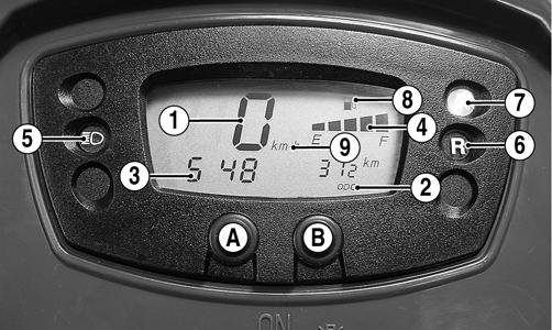
KM842D 4. Connect the red MaxiClip to the blue/red wire. The reverse indicator light (6) must illuminate. 5. Connect the red MaxiClip to the yellow/white wire and the black MaxiClip to the lavender/white wire.
The fuel quantity indicator (4) must sequence from empty to full; then all segments will disappear and the gas pump icon (8) will begin flashing. 6. Connect the red MaxiClip to the blue wire; then connect a voltmeter to the MaxiClips (red meter lead to red and black meter lead to black). 7. Set the meter selector to the DC Voltage position; then turn the ignition switch to the LIGHTS position and the light control switch to the HI beam position.
The tester must indicate battery voltage and the high beam indicator light (5) must illuminate. If the tester does not read battery voltage, troubleshoot the ignition switch, light control switch, or wiring harness and connectors. 8. Connect the red MaxiClip to the brown/black wire.
The tester must read battery voltage and the speedometer backlight must illuminate. If the tester does not read battery voltage, troubleshoot the ignition switch or wiring harness connectors. 9. Depress and hold the Mode/Set button (A). The speedometer should switch between mph and km/h as indicated by icon (9). 10. Depress and hold the Mode/Set button (B). The distance mode should shift between ODO and TRIP as indicated by icon (2). 11. Depress and hold the Mode/Set buttons (A) and (B) simultaneously. The hour segment of the clock should flash indicating the clock (3) is in the set mode. Release the Mode/Set button (A) and release (B) when the desired hour (1-24) appears. 12. Depress and release the Mode/Set button (A) to shift the clock set to the minute segment; then depress
Mode/Set button (B) to set the desired minute. NOTE: In the clock set mode, the gauge will default to normal operation 10 seconds after the Mode/Set buttons are released.
13. With the ignition switch in the ON position, elevate the rear wheels and rotate them several revolutions in either direction. The speed indicator LCD (1) should indicate a value less than zero.
Ignition Switch
The connector is the white one in front of the steering post. VOLTAGE NOTE: Perform this test on the lower side of the connector.
1. Set the meter selector to the DC Voltage position. 2. Connect the red meter lead to the red wire; then connect the black meter lead to ground. 3. The meter must show battery voltage. NOTE: If the meter shows no battery voltage, troubleshoot the battery, main fuse, or the main wiring harness. RESISTANCE CAUTION
Always disconnect the battery when performing resistance tests to avoid damaging the multimeter. NOTE: Perform this test on the upper side of the connector.
1. Turn the ignition switch to the ON position. 2. Set the meter selector to the OHMS position. 3. Connect the red tester lead to the red wire; then connect the black tester lead to the black wire. 4. The meter must show less than 1 ohm. 5. With the red tester lead connected to the red wire, connect the black tester lead to the black/white wire. 6. The meter must show less than 1 ohm. 7. Turn the ignition switch to the LIGHTS position. 8. Connect the red tester lead to the red wire; then connect the black tester lead to the brown wire. 9. The meter must show less than 1 ohm.
NOTE: If the meter shows more than 1 ohm of resistance, replace the switch.
Handlebar Control Switches
Two white connectors join the handlebar control switch pigtail to the main harness. The connectors are located in front of the steering post. NOTE: These tests should be made on the switch side of the connectors with the connectors uncoupled.
CAUTION
Always disconnect the battery when performing resistance tests to avoid damaging the multimeter. RESISTANCE (HI Beam) 1. Set the meter selector to the OHMS position. 2. Connect the red tester lead to the lavender wire; then connect the black tester lead to the brown/black wire. 3. With the dimmer switch in the HI position, the meter must show less than 1 ohm.
NOTE: If the meter shows more than 1 ohm of resistance, troubleshoot or replace the switch/component or the connector.
RESISTANCE (LO Beam) 1. Connect the red tester lead to the white wire. 2. With the dimmer switch in the LO position, the meter must show less than 1 ohm.
NOTE: If the meter reads more than 1 ohm of resistance, troubleshoot or replace the switch/component or the connector.
RESISTANCE (Starter Button) 1. Set the meter selector to the OHMS position. 2. Connect the red tester lead to the black/white wire; then connect the black tester lead to the yellow/red wire. 3. With the starter button depressed, the meter must show less than 1 ohm. 4. With the starter button released, the meter must show an open circuit. NOTE: If the meter does not show as specified, replace the switch/component or connector. RESISTANCE (Emergency Stop) 1. Set the meter selector to the OHMS position. 2. Connect the red tester lead to the brown/blue wire; then connect the black tester lead to the black/white wire. 3. With the switch in the OFF position, the meter must show an open circuit. 4. With the switch in the RUN position, the meter must show less than 1 ohm.
NOTE: If the meter shows more than 1 ohm of resistance, troubleshoot or replace the switch/component or the connector.
RESISTANCE (Reverse Override) 1. Set the meter selector to the OHMS position. 2. Connect the red tester lead to the green/red wire; then connect the black tester lead to the blue/red wire. The meter must show an open circuit. 3. Depress and hold the reverse override button. The meter must show less than 1 ohm of resistance.
NOTE: If the meter does not show as specified, replace the switch/component or connector.
Magneto Coils
VOLTAGE (Charging Coil - Output) 1. Set the meter selector to the DC Voltage position. 2. Connect the red tester lead to the positive battery post; then connect the black tester lead to the negative battery post. 3. With the engine running at a constant 5000 RPM (with the headlights on), the meter must show 1415.5 DC volts.
CAUTION
Do not run the engine at high RPM for more than 10 seconds.
NOTE: If voltage is lower than specified, test charging coil - no load. VOLTAGE (Charging Coil - No Load) The connector is the black and white one on the right rear side of the frame just above the regulator/rectifier. NOTE: Test the connector that comes from the engine. 1. Set the meter selector to the AC Voltage position. 2. Test between the three yellow wires for a total of three tests. 3. With the engine running at the specified RPM, all wire tests must show as specified.
CAUTION
Do not run the engine at high RPM for more than 10 seconds.
NOTE: If both voltage tests failed, check all connections, etc., and test again. If no voltage is present, replace the stator assembly. RESISTANCE (Charging Coil) CAUTION
Always disconnect the battery when performing resistance tests to avoid damaging the multimeter. 1. Set the meter selector to OHMS position. 2. Test between the three yellow wires for a total of three tests. 3. The meter reading must be within specification. RESISTANCE (Trigger Coil)
The trigger coil connector is located under the seat at the rear of the air filter housing. 1. Set the meter selector to the OHMS position.
CAUTION
Always disconnect the battery when performing resistance tests to avoid damaging the multimeter. 2. Connect the red tester lead to the blue wire; then connect the black tester lead to the green wire. The meter reading must be within specification. RESISTANCE (Signal Coil) The signal coil connector is located under the seat at the rear of the air filter housing. 1. Set the meter selector to the OHMS position. 2. Connect the red tester lead to the black wire; then connect the black tester lead to ground. The meter reading must be within specifications. PEAK VOLTAGE NOTE: All of the peak voltage tests should be made using the Fluke Model 77 Multimeter with Peak Voltage Reading Adapter. If any other type of tester is used, readings may vary due to internal circuitry. NOTE: The battery must be at full charge for these tests. Trigger Coil 1. Set the meter selector to the DC Voltage position. 2. Connect the red tester lead to the blue wire; then connect the black tester lead to the green wire. 3. Crank the engine over using the electric starter. 4. The meter reading must be within specification. Signal Coil 1. Set the meter selector to the DC Voltage position. 2. Connect the red tester lead to the black wire (engine side); then connect the black tester lead to a suitable ground. 3. Crank the engine over using the electric starter. 4. The meter reading must be within specifications.
Starter Motor
NOTE: The starter motor is not a serviceable component. If the starter motor does not operate, see Starter Relay. If the relay tests normal, replace the starter motor.
REMOVING/INSTALLING 1. Disconnect the battery.
CAUTION
Always disconnect the negative battery cable from the battery first; then disconnect the positive cable. 2. Remove the nut securing the positive cable to the starter; then remove the cable from the starter. 3. Remove the two cap screws securing the starter to the crankcase; then remove the starter. Account for the wiring forms and an O-ring. 4. Install the new starter motor; then tighten the cap screws to 7 ft-lb.
Starter Relay
VOLTAGE 1. Set the meter selector to the DC Voltage position. 2. Connect the red tester lead to the battery supply terminal (1); then connect the black lead to the starter terminal (2).
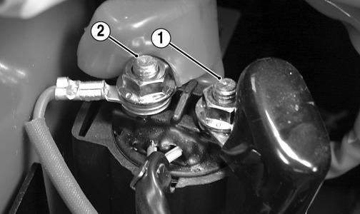
KM458A 3. Turn the ignition switch to the ON position. The meter must read battery voltage. NOTE: If battery voltage is not shown on the meter, troubleshoot the battery connections, ground connections, and starter cable connections.
4. With the transmission in neutral, depress the starter button. There should be an audible “click” from the starter relay and the meter should show 0 DC volts.
If the meter indicates as specified, replace the starter.
If there is no audible click and meter reads battery voltage, proceed to step 5. 5. Disconnect the two-wire connector on the starter relay pigtail from the main harness; then on the harness side, connect the red tester lead to the yellow/red wire and the black tester lead to the yellow/green wire. 6. With the transmission in neutral, depress the starter button. The meter must read battery voltage. If battery voltage is indicated, replace the starter solenoid. If no voltage is indicated, troubleshoot the gear position switch, starter button, ignition switch, or harness connectors.
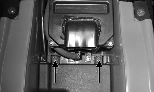
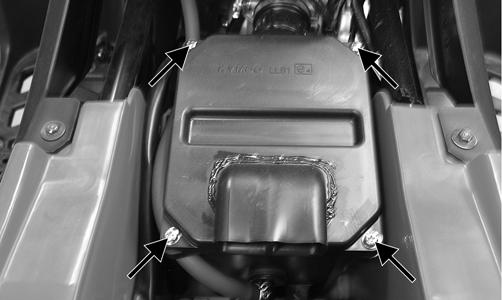
CDI Unit
The CDI is located beneath the seat at the rear of the gas tank. NOTE: The CDI unit is not a serviceable component. If the unit is defective, it must be replaced. The CDI is rarely the cause for electrical problems; however, if the CDI is suspected, substitute another CDI unit to verify the suspected one is defective.
NOTE: Prior to replacing the CDI unit to assure the CDI unit is defective, it is advisable to perform a CDI peak voltage test (see Ignition Coil) and/or perform a continuity test of the wiring harness from the CDI connector to the CDI unit.
Regulator/Rectifier
The regulator/rectifier is located on the right side of the frame above the rear wheel. Verify all other charging system components before the regulator/rectifier is replaced. TESTING 1. Start the engine and warm up to normal operating temperature; then connect a multimeter to the battery as follows. 2. Select the DC Voltage position; then connect the red tester lead to the positive battery post and the black tester lead to the negative battery post. 3. Start the engine and slowly increase RPM. The voltage should increase with the engine RPM to a maximum of 15.5 DC volts.
NOTE: If voltage rises above 15.5 DC volts, the regulator is faulty or a battery connection is loose or corroded. Clean and tighten battery connections or replace the regulator/rectifier. If voltage does not rise, check Voltage (Stator Coil - No Load) sub-section. If charging coil voltage is normal, replace the regulator/rectifier.
Start-in-Gear Relay
NOTE: The relay schematic is embossed on the relay housing for testing continuity. NOTE: The module and wiring harness are not a serviceable component and must be replaced as an assembly. TESTING The start-in-gear relay is located under the seat below the fuse block. To test the relay, use the following procedure. 1. Turn the ignition switch to the ON position; then compress the brake lever or depress the auxiliary brake pedal. There should be an audible “click” from the start-in-gear relay. NOTE: The brakelight should illuminate whenever either brake is applied. If the brakelight does not illuminate, troubleshoot the respective brakelight switch. 2. Apply the opposite brake from step 1. There should be an audible “click” from the start-in-gear relay. 3. Disconnect the four-wire connector from the start-ingear relay; then using a voltmeter, connect the red tester lead to the green/yellow wire (1) and the black tester lead to the green wire (3).
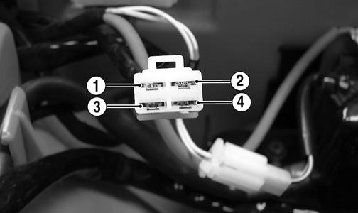
KM460A 4. With the ignition switch in the ON position, select the DC volts position on the tester; then apply either brake. The meter must read battery voltage. If battery voltage is observed and no audible “click” was heard in step 1 or 2, remove the tester leads and replace the start-in-gear relay. 5. Shift the gear selector out of neutral and connect a jumper wire between the yellow/green wire (2) and the green wire (4). 6. Momentarily depress the starter button. The starter should engage. If the starter engages, replace the start-in-gear relay. If the starter does not engage, troubleshoot the battery connections, starter relay, or starter connections.
Headlights
The connectors are the two 3-prong ones secured to the front bumper supports (one on each side) with cable ties. BULB VERIFICATION (LO and HI Beam) Visually inspect the bulb for broken filaments, blackening, or loose bulb base. VOLTAGE NOTE: Perform this test in turn on the main harness side of the connectors. Also, the ignition switch must be in the LIGHTS position and the engine must be running. 1. Set the meter selector to the DC Voltage position. 2. Connect the red tester lead to the green wire; then connect the black tester lead to the white wire. 3. With the dimmer switch in the LO position (LO beam), the meter must show battery voltage. 4. Connect the red tester lead to the blue wire. With the dimmer switch in the HI position (HI beam), the meter must show battery voltage. NOTE: If battery voltage is not shown in any test, inspect the fuses, battery, main wiring harness, connectors, or the left handlebar switch.
Taillight - Brakelight
The connector is the 3-prong one located under the rear fender assembly. BULB VERIFICATION Visually inspect the bulb for broken filaments, blackening, or loose bulb base. VOLTAGE (Taillight) NOTE: Perform this test on the main harness side of the connector. Also, the ignition switch should be in the LIGHTS position. 1. Set the meter selector to the DC Voltage position. 2. Connect the red tester lead to the brown/black wire; then connect the black tester lead to the green wire. 3. With the ignition key in the LIGHTS position, the meter must show battery voltage. NOTE: If the meter shows no voltage, inspect fuses, wiring harness, connectors, and switches. VOLTAGE (Brakelight) NOTE: Perform this test on the main harness side of the connector. Also, the ignition switch should be in the ON position and the brake (either foot pedal or hand lever) must be applied. 1. Set the meter selector to the DC Voltage position. 2. Connect the red tester lead to the green/yellow wire; then connect the black tester lead to the green wire. 3. With either brake applied, the meter must show battery voltage. NOTE: If the meter shows no voltage, inspect fuses, wiring harness, connectors, and switches.
Ignition Timing
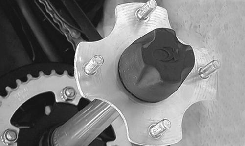
The ignition timing cannot be adjusted; however, verifying ignition timing can aid in troubleshooting other components. To verify ignition timing, use the following procedure. 1. Attach the Timing Light to the spark plug high tension lead; then remove the timing inspection plug from the left-side crankcase cover. 2. Using the Tachometer, start the engine and run at 1700 RPM; ignition timing should be 15° BTDC (“F” mark). 3. Install the timing inspection plug. If ignition timing cannot be verified, the rotor may be damaged, the key may be sheared, the trigger coil bracket may be bent or damaged, or the CDI unit may be faulty.
Troubleshooting
Problem: Spark absent or weak Condition Remedy 1. Ignition coil defective 1.Replace ignition coil 2. Spark plug defective 2.Replace plug 3. Trigger coil defective 3.Replace stator coil assembly 4. CDI unit defective 4.Replace CDI unit 5. Pick-up coil defective 5.Replace stator coil assembly Problem: Spark plug fouled with carbon Condition Remedy 1. Mixture too rich 1.Adjust carburetor 2. Idling RPM too low 2.Adjust carburetor 3. Gasoline incorrect 3.Change to correct gasoline 4. Air cleaner element dirty 4.Clean element 5. Spark plug incorrect (too cold) 5.Replace plug 6. Valve seals cracked - missing 6.Replace seals 7. Oil rings worn - broken 7.Replace rings Problem: Spark plug electrodes overheat or burn Condition
1. Spark plug incorrect (too hot) 2. Engine overheats 3. Spark plug loose 4. Mixture too lean Remedy
1.Replace plug 2.Check engine oil - clean cooling fans 3.Tighten plug 4.Change jets
Problem: AC generator does not charge Condition Remedy 1. AC generator lead wires/connections shorted - loose - 1.Repair - replace - tighten lead wires open 2. AC generator coils shorted - grounded - open 2.Replace stator coils 3. Regulator/rectifier defective 3.Replace regulator/rectifier Problem: AC generator charges, but charging rate is below the specification Condition Remedy 1. Lead wires shorted - open - loose (at terminals) 1.Repair - tighten lead wires 2. AC generator coils (charging) grounded - open 2.Replace stator coils 3. Regulator/rectifier defective 3.Replace regulator/rectifier 4. Cell plates (battery) defective 4.Replace battery Problem: Magneto overcharges Condition Remedy 1. Internal battery short circuited 1.Replace battery 2. Regulator/rectifier defective 2.Replace regulator/rectifier 3. Regulator/rectifier poorly grounded 3.Clean - tighten ground connection Problem: Charging unstable Condition Remedy 1. Lead wire intermittently shorting 1.Replace lead wire 2. AC generator internally shorted 2.Replace magneto 3. Regulator/rectifier defective 3.Replace regulator/rectifier Problem: Starter button not effective Condition Remedy 1. Battery charge low 1.Recharge - replace battery 2. Switch contacts defective 2.Replace switch 3. Starter motor brushes not seating 3.Repair - replace brushes 4. Starter relay defective 4.Replace relay 5. Emergency stop - ignition switch off 5.Turn on switches 6. Wiring connections loose - disconnected 6.Connect - tighten - repair connections 7. Starter bushings worn 7.Replace starter 8. Starter armature shorted - open 8.Replace starter 9. Brake switch defective 9.Replace switch Problem: Battery “sulfation” (Acidic white powdery substance or spots on surfaces of cell plates) Condition Remedy 1. Charging rate too low - too high 1.Replace battery 2. Specific gravity too low 2.Charge battery 3. Battery run-down - damaged 3.Replace battery 4. Electrolyte contaminated 4.Replace battery
1. Electrolyte contaminated 2. Battery short-circuited Remedy
1.Replace battery 2.Replace battery