10 minute read
General Information

NOTE: Some photographs and illustrations used in this manual are used for clarity purposes only and are not designed to depict actual conditions. NOTE: Whenever a part is worn excessively, cracked, or damaged in any way, replacement is necessary.
General Specifications
CHASSIS
Dry Weight (approx) Length (overall) Height (overall) Width (overall) Tire Size (Front) (Rear)
157.9 kg (349 lb) 177.8 cm (69.9 in.) 103.8 cm (40.9 in.) 95.0 cm (37.4 in.) AT21 x 7-10 AT22 x 10-10 Tire Inflation Pressure (Front) 27.6 kPa (4 psi) (Rear) 24.1 kPa (3.5 psi) MISCELLANY
Spark Plug Type Spark Plug Gap Gas Tank Capacity Engine Oil Capacity Transmission (Overhaul) Lubricant Capacity (Change) Gasoline (recommended)
Engine Oil (recommended)
Brake Fluid NGK DR8EA 0.6 mm (0.024 in.) 8.7 L (2.3 U.S. gal.) 1.0 L (1.06 U.S. qt) 400 ml (13.5 fl/oz) 300 ml (10.0 fl/oz) 87 Octane Regular Unleaded Arctic Cat ACX All Weather (Synthetic) DOT 4
Taillight/Brakelight Parking Lights Headlight 12V/5W/21W (2) 12V/5W (2) 12V/35W/35W (2) FUEL SYSTEM
Carburetor Type Main Jet Slow Jet Pilot Screw Setting (turns) Needle Jet Jet Needle Keihin PTG 22 98 35 1 7/8 3.6/2.5 2MKNN
Idle RPM
1600-1800 Float Arm Height 14.8 mm Throttle Cable Free-Play (at lever) 1-4 mm (1/16-3/16 in.) ELECTRICAL SYSTEM
Ignition Timing 15° BTDC (“F” mark) @1700 RPM
Spark Plug Cap Ignition Coil Resistance (primary) (secondary) 4200-5200 ohms 0.2-0.3 ohms 3200-4800 ohms
Ignition Coil Peak (primary/CDI) Voltage Magneto Coil Resistance (trigger) (charging) (signal) 85 DC volts
105-110 ohms Less than 1 ohm 720 ohms
Peak Voltage (trigger) (signal)
1.1-1.4 DC volts 220 DC volts Magneto Output (approx) 220W @ 5000 RPM Charging Coil Output (no load) 40-60 AC volts@3500 RPM
Specifications subject to change without notice.
VALVES AND GUIDES Valve/Tappet Clearance (intake/exhaust) 0.06 mm (cold engine) Valve Guide/Stem (intake) Clearance (max) (exhaust) 0.06 mm 0.08 mm
Valve Spring Free Length (min) (intake) (exhaust) Valve Spring Tension @ 33.7 mm (intake) Valve Spring Tension @ 38.4 mm (exhaust) 38.2 mm 44.3 mm 7.7-8.9 kg (22.5-38.4 lb)
CAMSHAFT AND CYLINDER HEAD Cam Lobe Height (min) (intake) 31.40 mm (exhaust) 31.13 mm Rocker Arm/Shaft Clearance (max)0.1mm Cylinder Head/Cover Distortion (max)0.05mm CYLINDER, PISTON, AND RINGS Piston Skirt/Cylinder Clearance (max)0.1 mm Cylinder Bore 62.030-62.045 mm Piston Diameter 18 mm from Skirt End 61.9 mm (min) Bore x Stroke 62 x 49.5 mm Cylinder Trueness (max)0.05mm Piston Ring to Groove Clearance (max) 0.09 mm (1st/2nd) Piston Ring End Gap - (top/middle) 0.10mm Installed (min) (oil) 0.20mm Piston Pin Bore (max)15.04 mm Piston Pin Outside Diameter (min)14.96mm CRANKSHAFT Connecting Rod (small end inside 15.06 mm diameter) (max) Connecting Rod (big end side-to-side) 0.55 mm (max) Crankshaft Runout (max)0.1 mm Oil Pressure at 60°C (140°F) (above) 0.3 kg/cm² (4.3 psi) @ 3000 RPM (below) 0.7 kg/cm² (10 psi) TRANSMISSION Clutch Wheel Inside Diameter (max)130.5 mm Centrifugal Clutch Shoe Lining Thickness 2.0 mm Clutch Engagement RPM 3250 Clutch Lock-Up RPM 4700 Movable Drive Face Bushing I.D. (max)27.06 mm Drive Face Collar (min)26.94 mm Drive Belt Width (min)19.0 mm Drive Pulley Weight Rollers (min)20.42 mm Movable Driven Face Spring Free Length 83.20 mm (min) Fixed Driven Face Hub O.D. (min)33.94 mm Movable Driven Face Bushing I.D. (max)34.06 mm
Torque Specifications
DRIVE TRAIN COMPONENTS
Part Part Bolted To Torque ft-lb N-m
Engine Mounting Through-Bolt Frame Engine Mounting Bracket Cap ScrewFrame 29 39 29 39
Gear Case Swing Arm 50 68
Wheel Lug Nut Hub 30 41
Hub Nut Axle 50 68
Rear Axle Nut* Axle EXHAUST COMPONENTS
86 117
Exhaust Pipe Cylinder Head 25 34 ELECTRICAL COMPONENTS Starter Motor Lead Nut Starter 36 5 in.-lb Starter Motor Mounting Cap Screw Crankcase 7 10 STEERING COMPONENTS Handlebar Clamp Cap Screw Steering Head 15 20 Steering Post Support Block Frame 15 20 Steering Post Nut Steering Post 50 68 Steering Knuckle Steering Knuckle 32 44 Tie Rod End Nut Steering Arm 29 40 Tie Rod End Nut Steering Knuckle 32 44 Tie Rod Lock Nut Tie Rod 22 30 BRAKE COMPONENTS Brake Hose Union Bolt Master Cylinder 24 33 Brake Bleed Screw Caliper 56 5 in.-lb Brake Caliper Mounting Cap Screw Swing Arm Housing 24 33 Master Cylinder Handlebar 9 12 Brake Pad Alignment Pin (Rear) Brake Caliper 13 18 Brake Caliper** (Rear) Swing Arm Housing 24 33 ENGINE/TRANSMISSION
Cylinder Head Nut Cylinder 14 19 Cylinder Head Cap Screw Crankcase 7 10 Rotor/Flywheel Nut Crankshaft 40 55 Drive Sprocket Lock Plate Driveshaft 40 55 Crankcase Cap Screw Crankcase 7 10 Engine Oil Screen/Filter Cap Crankcase 11 15 Shift Detent Bolt Transmission Case 35 48 Camshaft Chain Tensioner Cover Cam Chain 36 4 Bolt Tensioner in.-lb Camshaft Chain Tensioner Mount Cylinder Head 9 12 Centrifugal Clutch Housing* Driveshaft 40 54 Driven Pulley Retaining Nut Driven Shaft 43 59 (Transmission)
Drive Plate Nut*
Fixed Drive Face 43 59 Drive Pulley Nut Crankshaft 43 59 Transmission Drain Plug Transmission 21 29 Balancer Nut* Balancer Shaft 32 45 Oil Pump Crankcase 7 10 Oil Pump Baffle Crankcase 7 10 Oil Pump Driven Gear* Oil Pump 7 10 Starter One-Way Drive Nut* Crankshaft 68 92 Magneto Cover Crankcase 7 10 Outer Magneto Cover Magneto Cover 7 10 CVT Cover Cap Screw Crankcase 7 10 Part Part Bolted To Torque ft-lb N-m
A-Arm Pivot Nut Frame 32 44
Front Shock Absorber Mounting Nut* (Upper/Lower) Frame/A-Arm 29 39
SUSPENSION COMPONENTS (Rear) Swing Arm Pivot Nut Frame 50 68
Rear Shock Absorber Mounting Nut (Upper/Lower) Frame/Swing Arm 29 39
Axle Housing Cap Screw Swing Arm 50 68 * w/Red Loctite #271 ** w/Blue Loctite #242
Torque Conversions (ft-lb/N-m)
Gasoline - Oil - Lubricant
ft-lb N-m ft-lb N-m ft-lb N-m ft-lb N-m
1 1.4 26 35.4 51 69.4 76 103.4 2 2.7 27 36.7 52 70.7 77 104.7 3 4.1 28 38.1 53 72.1 78 106.1 4 5.4 29 39.4 54 73.4 79 107.4 5 6.8 30 40.8 55 74.8 80 108.8 6 8.2 31 42.2 56 76.2 81 110.2 7 9.5 32 43.5 57 77.5 82 111.5 8 10.9 33 44.9 58 78.9 83 112.9 9 12.2 34 46.2 59 80.2 84 114.2 10 13.6 35 47.6 60 81.6 85 115.6 11 15 36 49 61 83 86 117 12 16.3 37 50.3 62 84.3 87 118.3 13 17.7 38 51.7 63 85.7 88 119.7 14 19 39 53 64 87 89 121 15 20.4 40 54.4 65 88.4 90 122.4 16 21.8 41 55.8 66 89.8 91 123.8 17 23.1 42 57.1 67 91.1 92 125.1 18 24.5 43 58.5 68 92.5 93 126.5 19 25.8 44 59.8 69 93.8 94 127.8 20 27.2 45 61.2 70 95.2 95 129.2 21 28.6 46 62.6 71 96.6 96 130.6 22 29.9 47 63.9 72 97.9 97 131.9 23 31.3 48 65.3 73 99.3 98 133.3 24 32.6 49 66.6 74 100.6 99 134.6 25 34 50 68 75 102 100 136
RECOMMENDED GASOLINE The recommended gasoline to use is 87 minimum octane regular unleaded. In many areas, oxygenates are added to the gasoline. Oxygenated gasolines containing up to 10% ethanol or 5% methane are acceptable gasolines.
When using ethanol blended gasoline, it is not necessary to add a gasoline antifreeze since ethanol will prevent the accumulation of moisture in the fuel system.
CAUTION
Do not use white gas. Only Arctic Cat approved gasoline additives should be used.
RECOMMENDED ENGINE OIL CAUTION
Any oil used in place of the recommended oil could cause serious engine damage. Do not use oils which contain graphite or molybdenum additives. These oils can adversely affect clutch operation. Also, not recommended are racing, vegetable, non-detergent, and castor-based oils. The recommended oil to use is Arctic Cat ACX All Weather synthetic engine oil, which has been specifically formulated for use in this Arctic Cat engine. Although Arctic Cat ACX All Weather synthetic engine oil is the only oil recommended for use in this engine, use of any API certified SM 0W-40 oil is acceptable.
OILCHARTJ
RECOMMENDED TRANSMISSION LUBRICANT The recommended lubricant is Arctic Cat Gear Lube or an equivalent gear lube which is SAE approved 80W-90 hypoid. This lubricant meets all the lubrication requirements of the Arctic Cat ATV front differential and rear drive. FILLING GAS TANK
Since gasoline expands as its temperature rises, the gas tank must be filled to its rated capacity only. Expansion room must be maintained in the tank particularly if the tank is filled with cold gasoline and then moved to a warm area. ! WARNING
Always fill the gas tank in a well-ventilated area. Never add fuel to the ATV gas tank near any open flames or with the engine running. DO NOT SMOKE while filling the gas tank. ! WARNING
ATV0049B
Do not overflow gasoline when filling the gas tank. A fire hazard could materialize. Always allow the engine to cool before filling the gas tank. ! WARNING
Do not over-fill the gas tank. Tighten the gas tank cap securely after filling the tank.
Genuine Parts
When replacement of parts is necessary, use only genuine Arctic Cat ATV parts. They are precision-made to ensure high quality and correct fit. Refer to the appropriate Illustrated Parts Manual for the correct part number, quantity, and description.
Preparation For Storage
CAUTION
Prior to storing the ATV, it must be properly serviced to prevent rusting and component deterioration. Arctic Cat recommends the following procedure to prepare the ATV for storage. 1. Clean the seat cushion (cover and base) with a damp cloth and allow it to dry. 2. Clean the ATV thoroughly by washing dirt, oil, grass, and other foreign matter from the entire ATV.
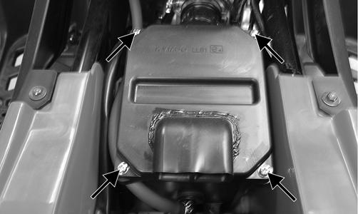
Allow the ATV to dry thoroughly. DO NOT get water into any part of the engine or air intake. 3. Either drain the gas tank or add Fuel Stabilizer to the gas in the gas tank. Remove the air filter housing cover and air filter. Start the engine and allow it to idle; then using Arctic Cat Engine Storage Preserver, slowly inject the preserver into the air filter opening for a period of 10 to 20 seconds; then stop the engine. Install the air filter and housing cover.
CAUTION
Rapid induction of oil or any liquid into a four-cycle engine can cause “hydraulic-lock” resulting in severe engine damage.
If the interior of the air filter housing is dirty, clean the area before starting the engine. 4. Drain the carburetor float chamber. 5. Plug the exhaust hole in the exhaust system with a clean cloth. 6. Apply light oil to the upper steering post bushing and plungers of the shock absorbers. 7. Tighten all nuts, bolts, cap screws, and screws. Make sure rivets holding components together are tight.
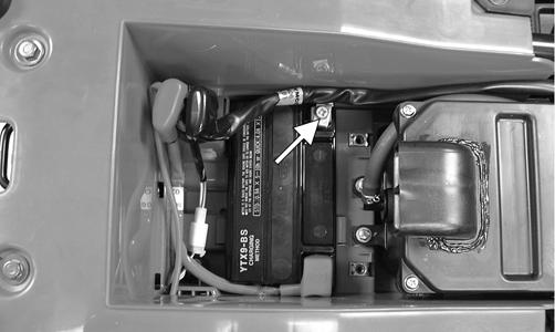
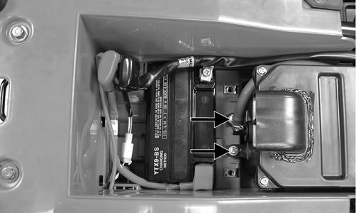
Replace all loose rivets. Care must be taken that all calibrated nuts, cap screws, and bolts are tightened to specifications. 8. Disconnect the battery cables; then remove the battery, clean the battery posts and cables, and store in a clean, dry area.
9. Store the ATV indoors in a level position.
CAUTION
This maintenance-free battery should be charged at the recommended rate every 30 days or permanent damage may occur if the battery completely discharges.
CAUTION
Avoid storing outside in direct sunlight and avoid using a plastic cover as moisture will collect on the ATV causing rusting.
Preparation After Storage
Taking the ATV out of storage and correctly preparing it will assure many miles and hours of trouble-free riding. Arctic Cat recommends the following procedure to prepare the ATV. 1. Clean the ATV thoroughly. 2. Clean the engine. Remove the cloth from the exhaust system. 3. Check all control wires and cables for signs of wear or fraying. Replace if necessary. 4. Change the engine oil and filter. 5. Charge the battery; then install. Connect the battery cables.
6. Check the entire brake systems (fluid level, pads, etc.), all controls, headlights, taillight, brakelight, and headlight aim; adjust or replace as necessary. 7. Tighten all nuts, bolts, cap screws, and screws making sure all calibrated nuts, cap screws, and bolts are tightened to specifications. 8. Check tire pressure. Inflate to recommended pressure as necessary. 9. Make sure the steering moves freely and does not bind. 10. Check the spark plug. Clean or replace as necessary.
CAUTION
The ignition switch must be in the OFF position prior to installing the battery or damage may occur to the ignition system.
CAUTION
Connect the positive battery cable first; then the negative.