11 minute read
Fuel/Lubrication/Cooling

Carburetor
KEY 1. Cap Seal 2. Cable Adjuster 3. Gasket 4. Spring 5. Needle Clip 6. E-Clip 7. Jet Needle 8. Throttle Valve 9. Needle Jet 10. Pilot Screw 11. Spring 12. Washer 13. O-Ring 14. Machine Screw 15. Cover Plate 16. O-Ring 17. O-Ring 18. Needle Jet Holder 19. Main Jet 20. Main Jet Holder 21. Slow Jet 22. Spring 23. Idle Adjust Screw 24. Spring 25. Choke Lever 26. Choke Cable
Bracket 27. Retaining Clamp 28. Machine Screw 29. Float Valve 30. Float Valve Clip 31. Float Arm Pin 32. Float 33. Float Chamber
Gasket 34. Float Chamber 35. Machine Screw 36. Drain Screw 37. O-Ring 38. Hose Clamp 39. Drain Tube
! WARNING
0743-813
Whenever any maintenance or inspection is performed on the fuel system during which there may be fuel leakage, there should be no welding, smoking, open flames, etc., in the area.
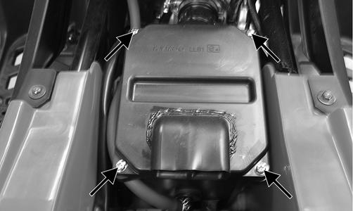
REMOVING 1. Remove the seat; then remove the left-side heat shield and turn the gas tank shut-off valve to the OFF position. 2. Remove the cap screws securing the air filter housing to the frame; then loosen the clamp securing air inlet boot to the carburetor and remove the air filter.
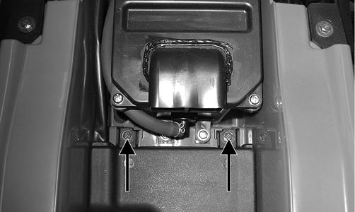
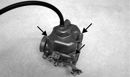
TR022B 3. Remove the choke assembly from the carburetor leaving the choke cable attached to the choke plunger. 4. Loosen the screw securing the choke cable to the carburetor; then disconnect the choke cable. 5. Remove the nuts securing the carburetor to the intake pipe; then remove the carburetor from the intake pipe. 6. Remove the gasline hose from the carburetor. 7. Remove the throttle valve cap and throttle cable/ throttle valve from the carburetor and remove the carburetor from the ATV. Secure the cable and throttle valve so the valve and needle will not be damaged. DISASSEMBLING 1. Remove the Phillips-head screws securing the float chamber; then remove the chamber. Account for the
O-ring.
TR203A
TR207 3. Lift the float assembly from the carburetor. Account for the float valve.

TR206A
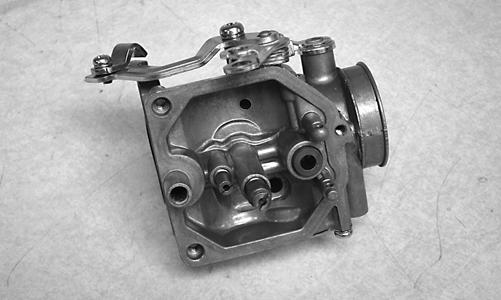
NOTE: Note the locations of the jets, pilot screw, and holder for assembling.
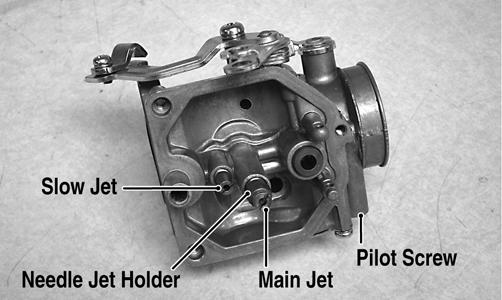
TR207A 4. Secure the needle jet holder with a wrench; then remove the main jet.

KC0030A 5. Remove the needle jet holder; then remove the slow jet. 6. Remove the pilot screw. Account for a spring, washer, and an O-ring.

TR211
CLEANING AND INSPECTING. ! WARNING
When drying components with compressed air, always wear safety glasses. CAUTION
DO NOT place any non-metallic components in partscleaning solvent because damage or deterioration will result. 1. Place all metallic components in a wire basket and submerge in carburetor cleaner. 2. Soak for 30 minutes; then rinse with clean, hot water. 3. Wash all non-metallic components with soap and water. Rinse thoroughly. 4. Dry all components with compressed air only making sure all holes, orifices, and channels are unobstructed. 5. Inspect the carburetor body for cracks, nicks, stripped threads, and any imperfections in the casting. 6. Inspect float for damage. 7. Inspect gasket and O-rings for distortion, tears, or noticeable damage. 8. Inspect tips of the jet needle, pilot screw, and the needle jet for wear, damage, or distortion.
9. Inspect the slow jet and main jet for obstructions or damage. NOTE: If the slow jet is obstructed, the mixture will be extremely lean at idle and part-throttle operation. 10. Inspect the float valve for wear or damage. 11. Inspect the carburetor mounting flange for damage and tightness. ASSEMBLING 1. Install the pilot screw, spring, washer, and O-ring.
TR209A
NOTE: Turn the pilot screw clockwise until it is lightly seated; then turn it counterclockwise the recommended number of turns as an initial setting. NOTE: Note the locations of the jets and holder during assembling procedures.
TR207A
2. Install the slow jet. Tighten securely. 3. Install the main jet into the needle jet holder and tighten securely; then install the needle jet holder assembly into the carburetor and tighten securely. 4. Place the float assembly (with float valve) into position and secure to the carburetor with the float pin.
TR205A
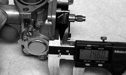
NOTE: Check float arm height by placing the carburetor on its side w/float contacting the needle; then measure with a caliper the height when the float arm is in contact with the needle valve. Float arm height should be 14.8 mm.
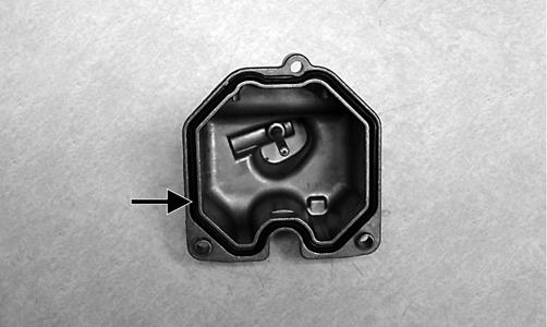
TR220 5. Place the float chamber into position making sure the
O-ring is properly positioned; then secure with the
Phillips-head screws.
TR204A
TR203A
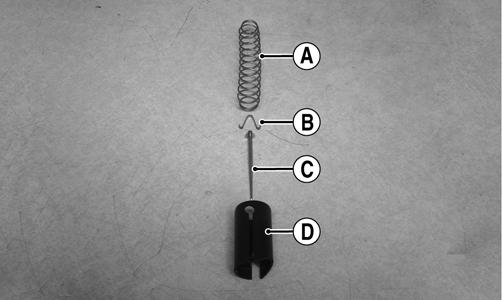
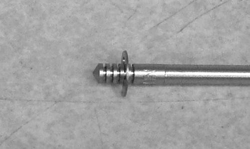
INSTALLING 1. If removed, connect the vent hose onto the carburetor. 2. If the throttle valve was removed, install the jet needle (C), needle holder (B), and spring (A) into the throttle valve (D) making sure the E-clip on the needle is in the fourth groove (counting from the top); then connect it to the throttle cable.
TR215A
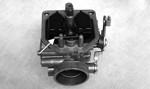
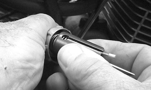
TR216 TR214 3. Slide the throttle valve into the carburetor making sure the alignment pin in the carburetor engages in the throttle valve groove; then secure the assembly into the carburetor with the cap and tighten securely.

TR202

TR053 4. Connect the gasline hose to the carburetor and secure with the clamp; then connect the choke cable and tighten the screw securely. 5. Making sure the O-ring is in position on the carburetor, position the carburetor onto the intake pipe and secure with two nuts. Tighten securely. 6. Install the air filter and secure the inlet boot to the carburetor with the clamp; then install two cap screws to secure the air filter housing to the frame and tighten securely. 7. Turn the gas tank shut-off valve to the ON position and check for leaks; then start the engine and adjust the idle as required (see Engine RPM (Idle) in this section). 8. Install the left-side heat shield and seat.
Throttle Cable Free-Play
To adjust throttle cable free-play, use the following procedure. 1. Slide the rubber boot away from the adjuster; then loosen the jam nut (1) from the throttle cable adjuster (2).
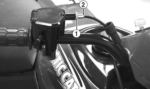
KM111A 2. Turn the adjuster until the throttle cable has proper free-play of 1-4 mm (1/16-3/16 in.) at the lever.

ATV-0047B 3. Tighten the jam nut against the throttle cable adjuster securely; then slide the rubber boot over the adjuster.
Engine RPM (Idle)
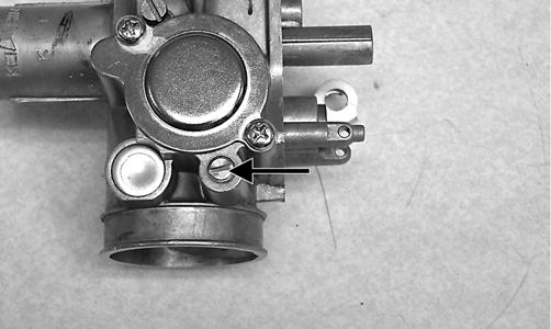
To properly adjust the idle RPM, a tachometer is necessary. To adjust idle RPM, use the following procedure. NOTE: The idle adjustment screw is located on the right side of the carburetor.
TR030 1. With the transmission in neutral, start the engine and warm it up to normal operating temperature. 2. Turn the idle adjustment screw clockwise one turn past the recommended RPM setting; then turn it counterclockwise to the correct setting of 1600-1800 RPM. ! WARNING
Adjust the idle to the correct RPM. Make sure the engine is at normal operating temperature before adjusting the idle RPM.
Gas Tank
! WARNING
Whenever any maintenance or inspection is made on the fuel system during which there may be fuel leakage, there should be no welding, smoking, open flames, etc., in the area. REMOVING 1. Turn the gas tank valve to the OFF position. 2. Remove the seat. 3. Disconnect the hose from the carburetor to the gas tank at the carburetor; then remove the gas tank cover. 4. Remove the cap screws securing the gas tank to the frame.
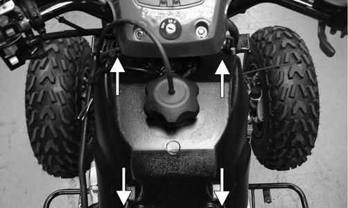
KM327A 5. Remove the vent hose; then remove the gas tank. CLEANING AND INSPECTING 1. Clean all gas tank components with parts-cleaning solvent.
2. Inspect all hoses for cracks or leaks. 3. Inspect gas tank valve, tank cap, and tank for leaks, holes, and damaged threads. 4. Inspect the gas gauge for proper operation. INSTALLING 1. Place the gas tank into position on the frame; then install the cap screws. Tighten securely. 2. Connect the gas hose from the carburetor. 3. Install the vent hose; then fill the gas tank with gasoline. 4. Turn the gas tank valve to the ON position and inspect for leakage. 5. Install the seat.
Gas Tank Valve
The ATV has a valve attached to the gas tank. There are three positions: ON, RES, and OFF.

KM043A In the OFF position, the valve will not allow gasoline to flow to the carburetor. In the ON position (the normal operating position), gasoline will flow from the tank to the carburetor. In this position 4.54 L (1.2 U.S. gal.) will remain in the tank as a reserve quantity. Moving the valve to the RES position will allow the operator to use the remaining gasoline in the tank. When turning the valve to any of the three positions, make sure the indicator is pointed directly at the position desired. REMOVING/INSPECTING
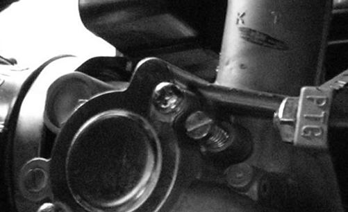
1. Remove the gas hose from the valve by releasing the clamp. 2. Remove the two machine screws securing the valve; then remove the valve. Account for the gasket. 3. Inspect the gasket and valve/tank mating surfaces for damage or deterioration. 4. Inspect for and remove any obstructions in the valve. INSTALLING 1. Place the valve and gasket into position on the tank and secure with the machine screws. Tighten securely. 2. Install the gas hose onto the valve with the clamp.
! WARNING
Drain the gas tank prior to this procedure.
Gas/Vent Hoses
Replace the gas hose every two years. Damage from aging may not always be visible. Do not bend or obstruct the routing of the carburetor vent hose. Make sure the vent hose is securely connected to the carburetor and the opposite end is always open.
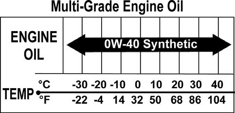
Oil Flow Chart
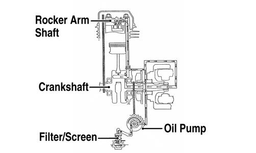
KM427A
Oil Pump
NOTE: Whenever internal engine components wear excessively or break and whenever oil is contaminated, the oil pump should be disassembled, cleaned, and inspected. NOTE: The oil pump is not a serviceable component. If the pump is defective, the oil pump must be replaced. REMOVING/DISASSEMBLING 1. Remove the oil pump from the engine (see Engine/
Transmission - Right-Side Components). 2. Remove the Phillips-head screw on the back side of the pump and separate the pump housing and cover.
Note the position of the inner and outer rotors and alignment pin for assembly. 3. Remove oil pump components. CLEANING AND INSPECTING NOTE: If any part is worn excessively, cracked, or damaged in any way, the oil pump must be replaced. 1. Clean all oil pump components.
2. Inspect the rotors for scoring and gouges. 3. Inspect the alignment pin, driveshaft, and driven sprocket for damage. 4. Inspect the pump housing and cover for cracks or damage. ASSEMBLING/INSTALLING 1. Place the rotors into the pump housing making sure the alignment pin is in the groove of the rotor. 2. Place the cover onto the pump housing. 3. Secure the pump with the Phillips-head screw coated with red Loctite #271. 4. Install the oil pump into the engine (see Engine/
Transmission - Right-Side Components).
Troubleshooting
Problem: Starting impaired Condition
1. Slow jet obstructed 2. Slow jet passage obstructed 3. Carburetor leaking air 4. Choke valve not operating properly Remedy
1.Clean jet 2.Clean passage 3.Tighten - adjust - replace gasket 4.Check - adjust choke/choke cable
Problem: Idling or low speed impaired Condition Remedy 1. Slow jet obstructed - loose 1.Clean - tighten jet 2. Slow jet outlet obstructed 2.Clean outlet 3. Pilot screw setting incorrect 3.Adjust screw 4. Choke valve not fully open 4.Adjust choke 5. Float height incorrect 5.Adjust float height Problem: Medium or high speed impaired Condition Remedy 1. High RPM “cut out” against RPM limiter 1.Shift into higher gear - decrease RPM speed 2. Main jet obstructed 2.Clean main jet 3. Needle jet obstructed 3.Clean needle jet 4. Filter obstructed 4.Clean filter 5. Float height incorrect 5.Adjust float height 6. Starter valve not fully open 6.Adjust choke/choke cable Problem: Overflow and fuel level fluctuations Condition
1. Float valve worn - damaged 2. Float valve spring broken 3. Float fuel logged 4. Float valve dirty 5. Float height too high - too low Remedy
1.Replace valve 2.Replace spring 3.Replace float 4.Clean valve 5.Adjust float height