35 minute read
Drive System

GENERAL INFORMATION The die-cast aluminum housings have been assembled with thread-rolling screws (trilobular). When assembling with these screws, start the screws carefully into the housing; then use the following torque values.
Size New Housing Reassembled Housing
M6 (Torx T-30 Recess)9 ft-lb 8 ft-lb M8 (Torx T-40 Recess)28 ft-lb 23 ft-lb
NOTE: Never reuse a lock nut. Once a lock nut has
been removed, it must be replaced with a new lock nut.
SPECIAL TOOLS A number of special tools must be available to the technician when performing service procedures in this section. Refer to the current Special Tools Catalog for the appropriate tool description.
Description p/n
Backlash Measuring Tool (24-Spline Axle) 0544-010 Backlash Measuring Tool (27-Spline Axle) 0544-011 CV Boot Clamp Tool 0444-120 Hose Clamp Pliers 0644-545 Internal Hex Socket 0444-104 Pinion Gear/Shaft Removal Tool 0444-127 Gear Case Seal Installer Tool 0444-224 U-Joint Separator Tool 0444-128
NOTE: Special tools are available from the Arctic
Cat Service Department.
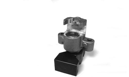
Front Drive Actuator
NOTE: The actuator is not a serviceable compo-
nent. If it is defective, it must be replaced.
NOTE: The actuator will operate only when the igni-
tion switch is in the ON position.
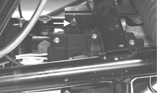
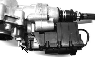
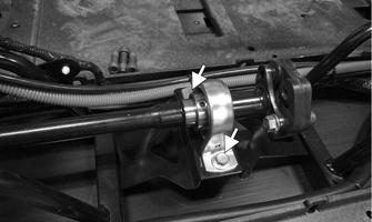
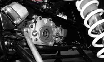
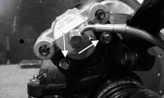
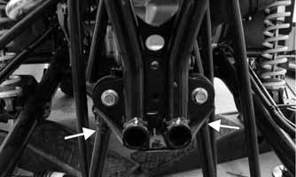
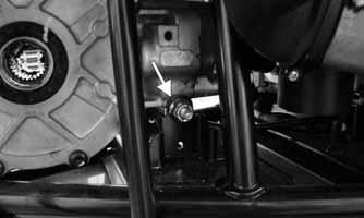
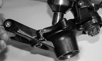
The front drive actuator is located on the left side of the front differential input housing. With the engine stopped and the ignition switch in the ON position, a momentary “whirring” sound can be heard each time the drive select switch is shifted. If no sound is heard, see Electrical System. If the actuator runs constantly or makes squealing or grinding sounds, the actuator must be replaced. REMOVING 1.Select LOCK on the drive select switch; then disconnect the connector on the actuator harness. 2.Using a T-30 torx wrench, remove the mounting cap screw from the driveshaft side of the actuator.
PR189A
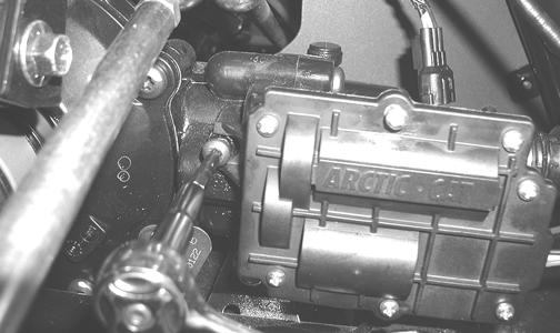
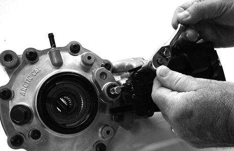
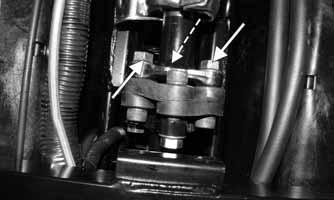
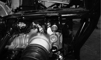
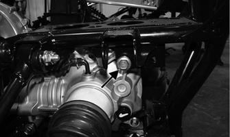
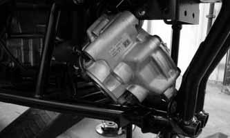
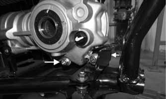
3.Remove the mounting cap screw from above the actuator on the suspension side.
PR190A
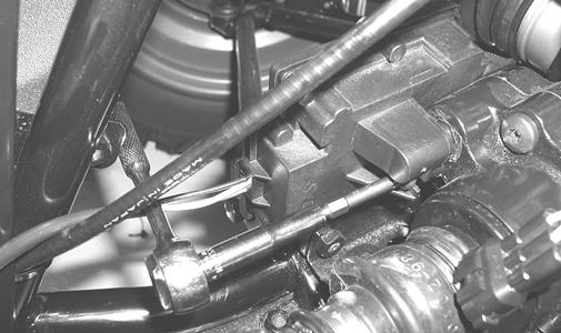
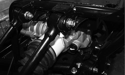
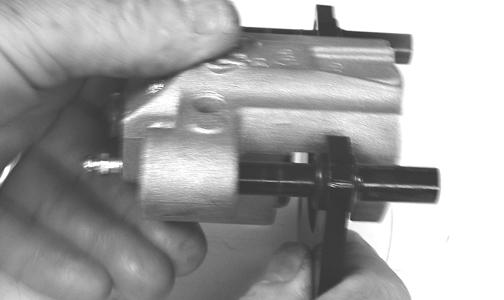
4.Loosen but do not remove the mounting cap screw at the front of the actuator; then slide the actuator to the rear enough to clear the slotted mounting tab and the selector shaft. Remove from the right side.
AG928
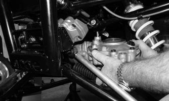
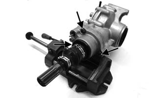
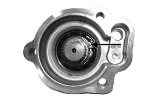
INSTALLING 1.Lubricate the O-rings on the actuator; then ensure all mounting surfaces are clean and free of debris. 2.Align the actuator with the selector shaft and slide it forward onto the shaft taking care to engage the cap screw in the slot of the front mounting tab. NOTE: Make sure to properly align the differential
lock actuator lever with the hole in the differential lock plunger.
GC002A
3.While holding the actuator firmly forward, tighten the front cap screw to hold the actuator in place; then install but do not tighten the two remaining cap screws.
GC001
4.Loosen the front cap screw; then tighten the cap screw on the driveshaft side.
AG926
NOTE: It is important to tighten this cap screw while
the others are loose to ensure proper seating of the actuator.
5.Tighten the remaining cap screws; then connect the electrical plug to the main harness. 6.Turn the ignition switch to the ON position and check the operation by shifting the drive select switch several times. 7.Secure the wiring harness to the frame with a nylon cable tie; then install the inner fender panel.
Front Differential
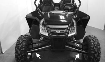
REMOVING 1.Remove the seats and center consoles; then drain the lubricant from the differential. 2.Using an appropriate jack or lift, raise the vehicle so the wheels are off the floor and support with jackstands under the lower A-arms.
WC549A
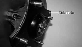
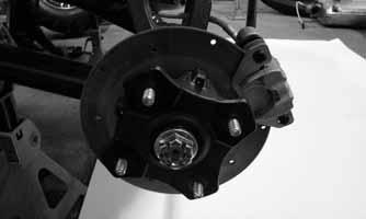
3.Remove the front wheels and account for the hub plates; then remove the hub nuts and Belleville washers.

WC240B

WC304
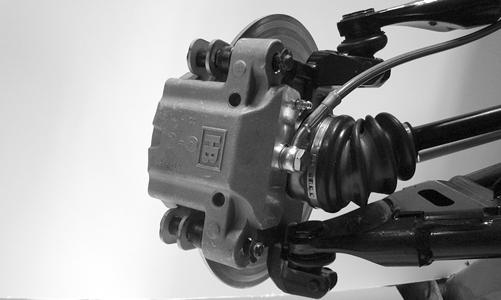
4.Remove the left and right brake calipers; then remove the hub/brake disc assemblies.
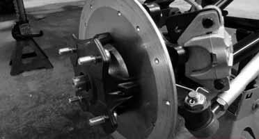
WC269
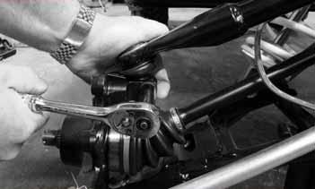
5. Holding the upper A-arm/ball joint down into the knuckle, remove and discard the retaining cap screw.
PR729C
8.From inside the vehicle, remove the front carrier bearing snap ring; then loosen the set screws securing the carrier bearings to the driveshaft.
WC271
6.Raise the upper A-arm to dislodge the ball joint from the knuckle; then tip the knuckle outward and remove the axle from the knuckle.
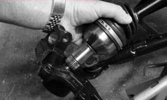
WC272
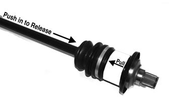
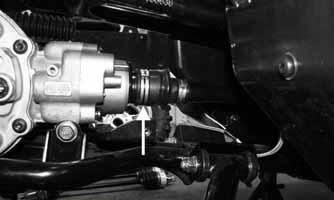
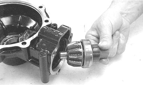
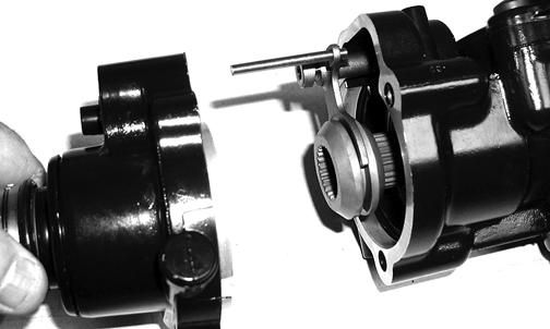
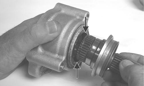
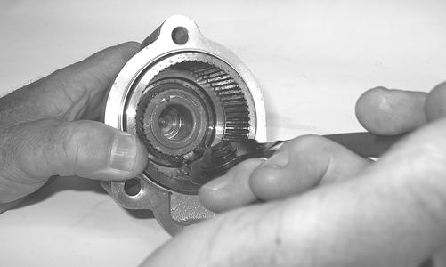
7.Push in on the axle shaft while pulling outward on the axle coupler and remove the axle assembly from the differential.
WC697A
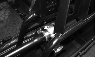
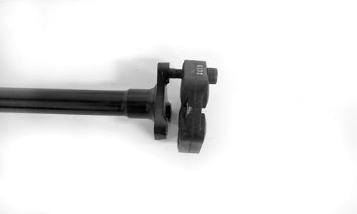
9.Disconnect the drive line coupler by removing three nuts from the Allen-head bolts; then separate the drive line to allow the front shaft to move rearward.
WC267A
10. Remove the front drive actuator from the differential; then remove the front boot clamp from the front drive coupler and slide the boot off.
WC275A
11.From inside the vehicle, slide the driveshaft to the rear sufficiently to allow differential to move to the rear 68 inches. 12.Remove the upper and lower through-bolts; then slide the differential rearward and lay it on the right side.
Remove from the vehicle from either left or right side.
WC 277
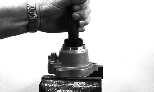
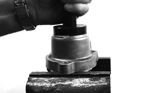
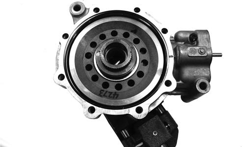
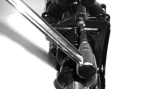
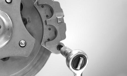
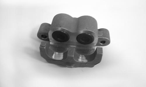
Disassembling Input Shaft 1.Using a T-40 torx wrench, remove the cap screws securing the pinion housing.
GC004A
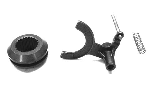
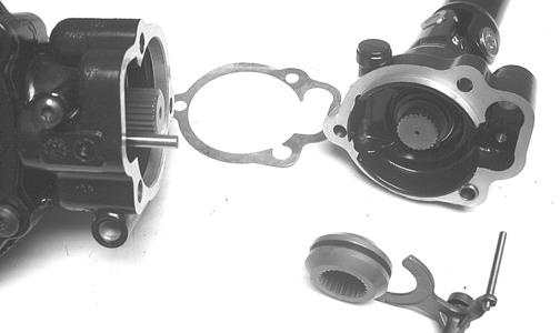
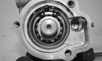
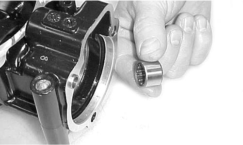
2.Using a rubber mallet, remove the housing. Account for a gasket. Remove the fork, collar, and spring. Note the location of all the components for assembling purposes.
GC015
CD106
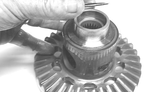
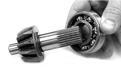
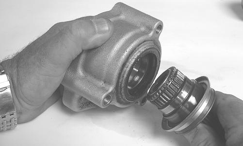
3.Remove the snap rings from the input shaft; then remove the input shaft from the pinion housing.
GC009A
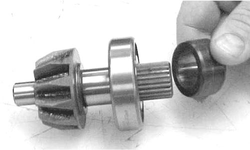
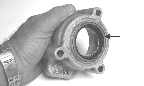
4.Using a seal removal tool, remove the input shaft seal.
Account for a spacer.
GC010
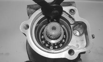
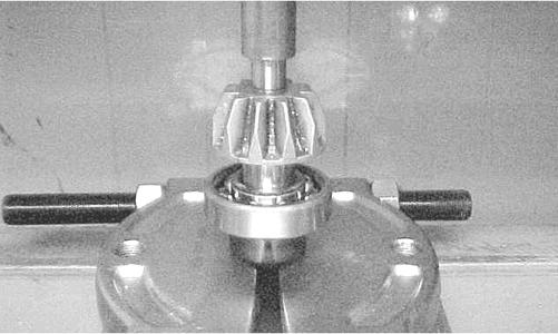
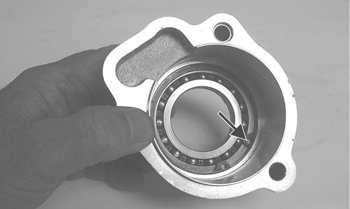
5.Remove the snap ring securing the input shaft bearing; then place the pinion housing in a press and remove the bearing.
GC011
AF984
KX219
Assembling Input Shaft 1.Place the pinion housing in a press and install the input shaft bearing. Secure the bearing with the existing snap ring making sure the sharp edge of the snap ring faces to the outside.
GC012
GC011
2.Install the input shaft seal making sure it is fully seated in the edge of the housing.
GC014
3.Lubricate the input shaft with High-Performance #2
Molybdenum Disulphide Grease packing the boot ribs and splines; then assemble allowing excess grease to freely escape. Slight pressure on the boot will be present during assembly. Secure with new clamps. NOTE: Any time drive splines are separated, clean
all splines with parts-cleaning solvent and dry with compressed air; then lubricate with recommended grease.
4.Install the input shaft into the pinion housing; then secure in the bearing with a circlip.
GC009A
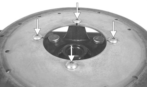
5.Place the pinion housing with new gasket onto the differential housing; then secure with existing cap screws. Tighten to 23 ft-lb. NOTE: If a new differential housing is being
installed, tighten the cap screws to 28 ft-lb.
KX209
GC004A
Disassembling Differential Assembly NOTE: This procedure can be performed on a rear
gear case.
1.Using a T-40 torx wrench, remove the cap screws securing the pinion housing. Account for the coupler, fork, and spring (differential only).
GC015
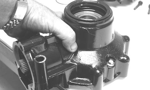
2.Using a T-40 torx wrench, remove the cap screws securing the differential cover. 3.Using a plastic mallet, tap lightly to remove the differential cover. Account for an O-ring.
KX174
NOTE: If the cover is difficult to remove, pry on the
cover in more than one recessed location.
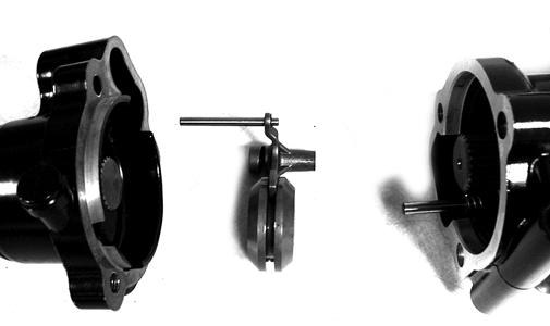
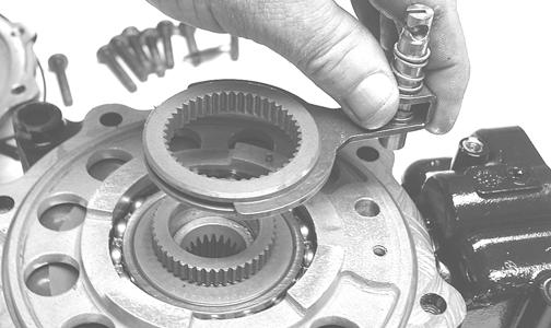
4.Remove the splined coupler, shifter fork, pin, and spring of the differential lock assembly and set aside.
Note position of parts for assembling purposes.
KX175
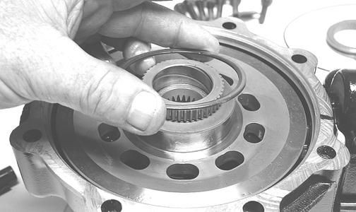
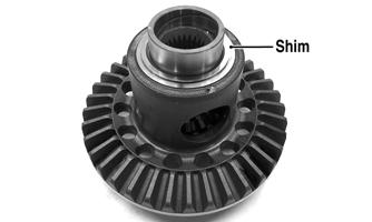
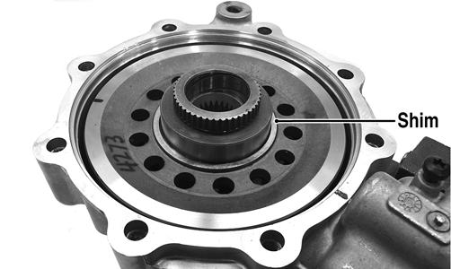
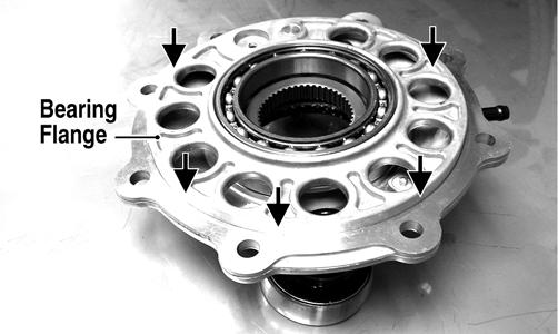
5.Remove the left differential bearing flange assembly and account for a shim. Mark the shim as left-side.
KX177
KX178
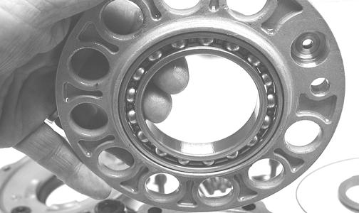
6.Place the differential with the open side down; then lift the housing off the spider assembly. Account for shim(s) and mark as right-side.
KX179
KX181
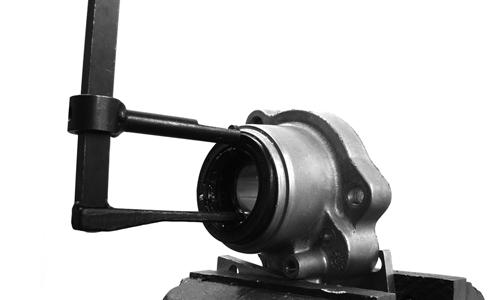
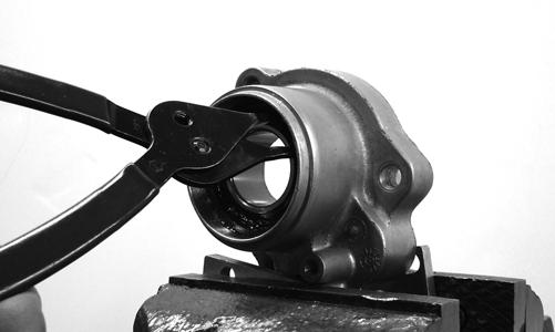
Disassembling Pinion Gear 1.Remove the internal snap ring securing the pinion bearing in the housing.
WC430
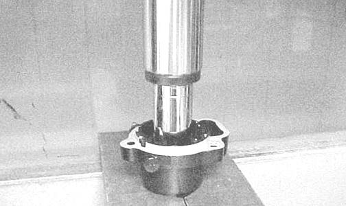
2.Using the Pinion Gear/Shaft Removal Tool and a hammer, remove the pinion gear from the gear case housing.
CC878
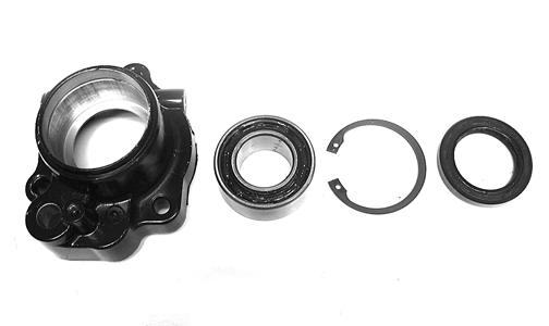
3.Secure the pinion gear in a bearing puller; then remove the pinion bearing using a press. Account for a collar and a bearing.
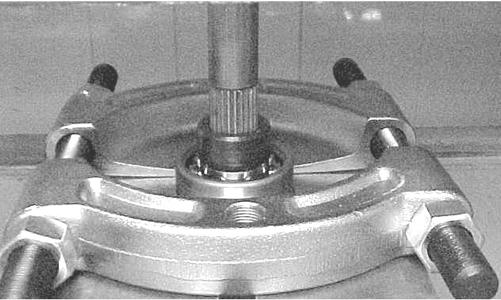
CC879
4.Remove any reusable parts from the gear case housing; then discard the housing and lock collar. Assembling Pinion Gear 1.Install the bearing onto the pinion shaft. Install the pinion shaft collar.
CC882
CC883
2. Place the pinion assembly in a bearing puller; then install the bearing using a press.
CC884
3.Using a propane torch, heat the gear case housing to approximately 200° F; then install the pinion assembly. 4.Install the internal snap ring with the sharp side directed away from the bearing.
WC429
Shimming Procedure/Shim Selection
Case-Side Shims (Backlash) p/n mm in. 0402-405 1.3 0.051 0402-406 1.4 0.055 0402-407 1.5 0.059 0402-408 1.6 0.063 0402-409 1.7 0.067
Cover-Side Shims (Ring Gear End-Play) p/n mm in.
1402-074 1.3 0.051 1402-075 1.4 0.055 1402-076 1.5 0.059 1402-077 1.6 0.063 1402-078 1.7 0.067 It is very important to adjust bevel gears for the proper running tolerances. Gear life and gear noise are greatly affected by these tolerances; therefore, it is very important to properly adjust any gear set prior to final assembly. The following procedure can be used on both front differential or rear drive gear case. NOTE: All bearings must be installed in the gear case
and the pinion properly installed before proceeding.
Backlash NOTE: Always set backlash prior to any other shim-
ming.
1.Install the existing shim or a 0.051-0.055-in. shim on the gear case side of the ring gear assembly.
GC031A
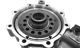
2.Install the ring gear with shim in the gear case; then while holding the pinion stationary, rock the ring gear forward and back to determine if any backlash exists.
If no backlash exists, install a thicker shim and recheck.
GC036A
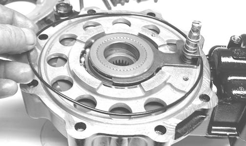
3.Install the bearing flange onto the gear case cover making sure the alignment/locating pin engages the locating hole in the cover; then make sure the bearing flange is completely seated in the cover.
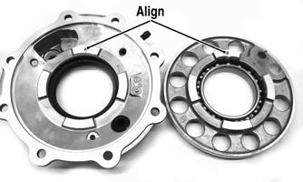
GC032A GC033A
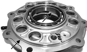
4.Install the existing shim or a 0.063 in. shim on the cover side of the ring gear; then place the assembled gear case cover onto the gear case and secure with three cap screws. Tighten evenly using a crisscross pattern.
GC036B
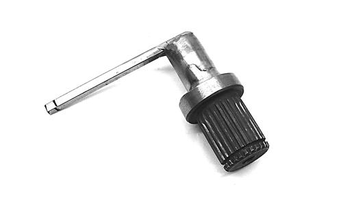
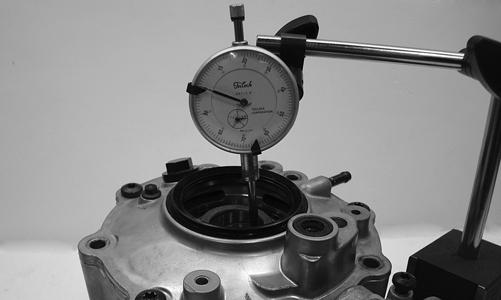
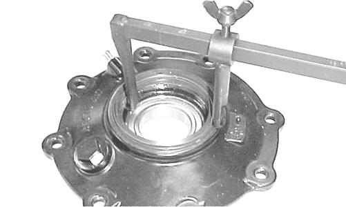
5.Place the appropriate Backlash Measuring Tool into the splines of the ring gear and install a dial indicator making sure it contacts the gauge at a 90° angle and on the index mark.
GC040
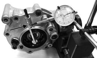
GC039A
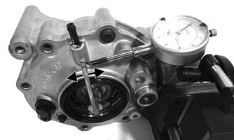
6.Zero the dial indicator; then while holding the pinion stationary, rock the ring gear assembly forward and back and record the backlash. Backlash must be 0.011-0.015 in. If backlash is within specifications, proceed to Ring Gear End-Play. If backlash is not within specifications, increase shim thickness to increase backlash or decrease shim thickness to decrease backlash. NOTE: Higher backlash settings usually result in
quieter gear operation.
GC037A
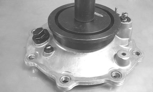
Ring Gear End-Play After correcting backlash, ring gear end-play can be adjusted. To adjust end-play, use the following procedure. 1.Secure the gear case in a holding fixture with the cover side up; then install a dial indicator contacting the ring gear axle flange.
GC035
2.Zero the dial indicator; then push the ring gear toward the dial indicator and release. End-play should be 0.004-0.008 in.
3.To increase end-play, decrease the shim thickness. To decrease end-play, increase the shim thickness. NOTE: Once proper backlash and end play are
established, the gear case can be assembled (see Assembling Differential Assembly in this sub-section).
CC888
Assembling Differential Assembly 1.With the pinion gear and new bearings installed, place the selected (backlash) shim on the gear case side of the ring gear with the chamfered side toward the ring gear; then install into gear case/differential housing.
GC031A
GC020
2.Place the selected (end-play) shim, chamfered side toward the gear, onto the cover side of the ring gear.
GC036B
NOTE: The spider and ring gear assembly must be
replaced as a complete unit.
3.Assemble the fork and sliding collar into the cover assembly; then install the left bearing flange/bearing assembly and seat firmly into the cover.
CF266A
CF267A
4.Apply a liberal coat of grease to the O-ring; then install it on the assembled cover assembly making sure to seat the O-ring completely down around the circumference of the bearing flange.
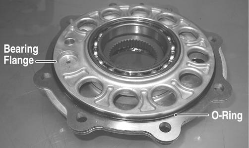
CF275A
5.Making sure the O-ring is properly positioned on the differential housing cover assembly, install the cover with existing cap screws (coated with green Loctite #270). Account for the ID tag. Tighten the cap screws evenly to 23 ft-lb. NOTE: Grease can be applied to the O-ring for ease
of assembling.
NOTE: If a new housing is being installed, tighten
the cap screws to 28 ft-lb.
6.Install the shift fork shaft w/spring into the housing making sure the shaft O-ring is positioned to the inside.
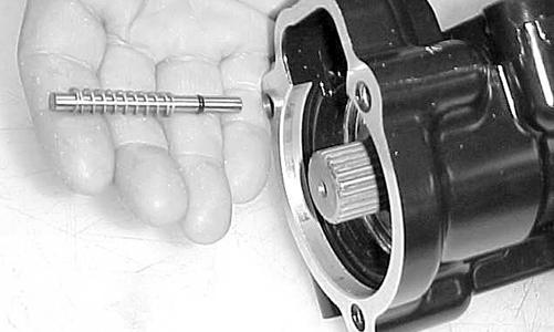
CC892
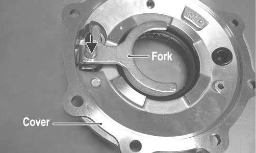
7.Install the shift fork assembly making sure the fork leg is facing upward. Apply a small amount of oil to the gasket; then install the gasket.
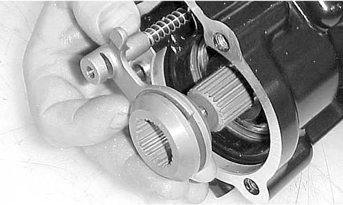
CC893
8.Place the input shaft assembly onto the gear case housing; then secure with the existing cap screws.
Tighten to 23 ft-lb.
CD103
CD110
Removing/Installing Axle Seal NOTE: This procedure can be performed on a rear
gear case.
1.Remove the seal using a seal removal tool.
CC899
NOTE: Prior to installing the seal, apply High-Per-
formance #2 Molybdenum Disulphide grease to the seal outside diameter.
2.Using Gear Case Seal Installer Tool, evenly press the seal into the cover bore until properly seated.
CF278
CAUTION
Make sure the tool is free of nicks or sharp edges or damage to the seal may occur.
3. Repeat steps 1-2 for the opposite side. INSTALLING DIFFERENTIAL 1.Lay the differential assembly on its right side and place in the frame of the vehicle; then turn it upright and maneuver into the mounting brackets.
WC277
2.Apply molybdenum grease to the splines and install the forward driveshaft into the differential splined coupler; then install the boot clamp using the appropriate boot clamp tool.
WC267A
3.Install the two through-bolts and secure the differential with new lock nuts. Tighten to 38 ft-lb.
WC276A
4.Install the front carrier bearing snap ring; then tighten the two set screws on each bearing to 78 in.-lb.
WC699A
5.Install the rear driveshaft and secure with new “patchlock” cap screws. Tighten to 40 ft-lb.
CAUTION
Always replace “patch-lock” fasteners with new fasteners or drive line damage may occur.
WC701 WC275A
NOTE: To secure the clamp, use Hose Clamp Pliers.
6.Using new O-rings with clean grease applied, install the front drive actuator on the differential and tighten the three mounting screws securely. Connect the front drive actuator connector. 7.Apply fresh multi-purpose grease to the splines; then install the front axles into the differential pushing in on the axle shafts to seat the splines into the differential.
PR729C
8.Install the axles into the knuckles; then swing the knuckles vertical and engage the ball joint shanks into the knuckles. While holding the ball joint securely in the knuckle, secure with a new “patch-lock” cap screw. Tighten to 35 ft-lb.
WC272

WC271
9. Install the hub assemblies onto the axles; then apply
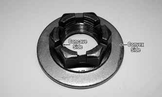
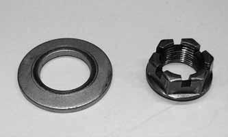
Loctite primer and red Loctite #277 to the axle threads. 10.Engage the hub nut into the Belleville washer on the convex side; then with the concave side of the washer directed toward the hub, install the nut and washer.
Keeping the nut and washer engaged, tighten the hub nut to 250 ft-lb.
WC303A
11.Install the brake calipers and secure with the anchor bolts and E-clips. Tighten to 34 ft-lb.
WC268A
12.Install the hub plate and wheel onto each hub; then using a crisscross pattern, tighten the wheel nuts in 20 ft-lb increments to a final torque factor of 80 ft-lb.

WC317A
NOTE: If the hub plate cannot be fully installed due
to misalignment of the nut, tighten the nut until properly aligned and the plate is fully seated.
13.Tighten the differential drain plug to 45 in.-lb; then remove the fill/level plug. 14.Pour in the recommended grade and amount of lubricant until the lubricant shows on the threads of the level hole; then install the fill/level plug and tighten to 16 ft-lb. 15.Install the hub caps; then install the forward belly panel. Remove the jack stands, and lower the vehicle.
Drive Axles
REMOVING/INSTALLING DRIVE AXLES NOTE: For removing/installing a rear drive axle, see
Rear Gear Case or Front Differential in this section.
CLEANING AND INSPECTING AXLES NOTE: Always clean and inspect the drive axle com-
ponents to determine if any service or replacement is necessary.
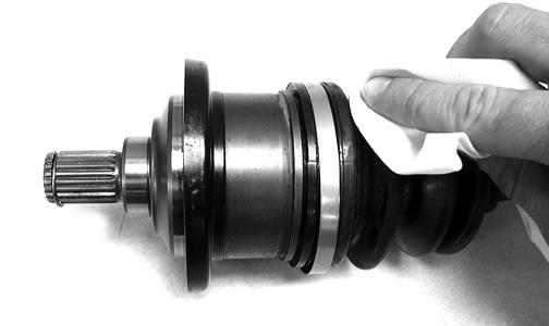
1.Using a clean towel, wipe away any oil or grease from the axle components.
CD019
2.Inspect boots for any tears, cracks, or deterioration. NOTE: If a boot is damaged in any way, it must be
replaced with a boot kit.
DISASSEMBLING/ASSEMBLING AXLES NOTE: To disassemble/assemble axles, see the
instructions included in boot repair kit.
Rear Gear Case
REMOVING 1.Using a suitable lift or jack, raise and support the vehicle with the rear wheels off the floor and weight off the suspension.
2.Remove the wheels and account for the hub plates; then remove the hub nuts and Belleville washers.
AT THIS POINT
If disassembling the rear gear case, drain the lubricant.

WC240B
WC304
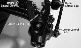
3.Remove the brake calipers from the knuckles. 4.Leaving the lower trailing arm connected to the knuckle, remove the upper trailing arm and lateral link from the knuckle; then move the top of the knuckle outward and rotate forward to disengage the axle from the axle bearing.
WC282B

WC286A
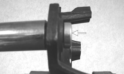
5.Remove the rear axles from the rear drive gear case by pushing the axle shaft toward the gear case and pulling the CV/spline shaft out. Account for one O-ring on each axle shaft.
PR729C
6.Remove the two lower lateral links from the frame; then remove the lower rear gear case mounting cap screw.
WC287A
WC170B
7.Remove the lower frame gear case bracket; then remove the left upper lateral link and the upper rear gear case through-bolt.
WC169A
WC170C
8.Remove the lower front through-bolt; then remove the boot clamp on the input drive coupler and slide the gear case to the rear until drive coupler disengages.
WC288A
9.Lay the gear case on its left side and remove from either side of the vehicle.
WC290
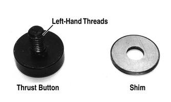
RING GEAR/THRUST BUTTON Removing 1.Remove the cap screws securing the gear case cover to the gear case; then remove the ring gear. 2.Remove the thrust button from the gear case cover (left-hand threads). Account for a shim. Inspecting 1.Inspect the ring gear for excessive wear, missing or chipped teeth, or discoloration. 2.Inspect the thrust button for excessive wear or discoloration. 3.Inspect the bearings for discoloration, roughness, or excessive wear. NOTE: For servicing bearings or seals, see Front
Differential in this section.
Installing/Shimming NOTE: Ring gear clearance must be adjusted prior
to selecting shim for the thrust button.
1.Install the thrust button with shim into the gear case cover and tighten securely (left-hand threads).
GC057A
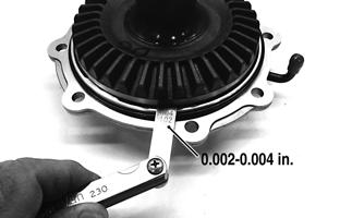
2.Place the ring gear with selected shim into the cover and measure the ring gear to thrust button clearance with a thickness gauge. Clearance should be 0.0020.004 in.
GC058A
3.If clearance is as specified, remove the ring gear and thrust button; then place a drop of red Loctite #271 on the threads and tighten to 8 ft-lb (left-hand threads). 4.If clearance is not as specified, repeat steps 1 and 2 using thicker (clearance too great) or thinner (clearance too small) until correct specification is reached. REAR DRIVE INPUT SHAFT/ HOUSING Removing/Disassembling 1.Remove the cap screws securing the rear drive input shaft/housing to the rear gear case; then remove the input housing assembly.
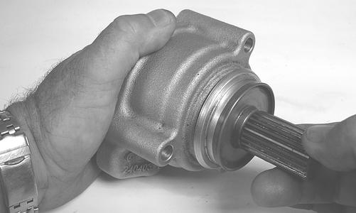
GZ183
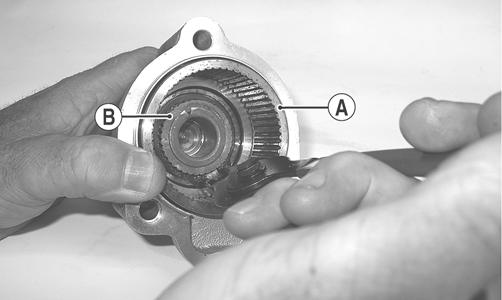
2.Remove the clutch pack from the clutch basket; then remove the snap ring securing the clutch basket (A) to the input shaft (B) and remove the clutch basket.
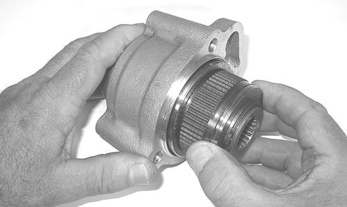
GZ392
GZ176A
GZ177
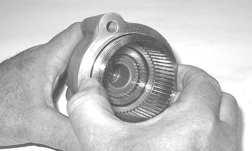
3.Remove the input shaft from the input housing; then remove the oil seal.
GZ180
GZ182A
4.Remove the snap ring retaining the input bearing and using an appropriate bearing driver, press the bearing from the housing.
GZ184A
Cleaning and Inspecting 1.Wash all parts in parts cleaning solvent and dry with compressed air.
! WARNING
Always wear safety glasses when working with compressed air.
2.Clean all gasket material and sealant from mating surfaces. 3.Inspect bearings, shafts, and housing for excessive wear, cracks, or discoloration. 4.Inspect the clutch basket for wear in splines or cracks in the housing.
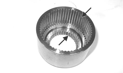
GZ178A
5.Inspect the clutch pack for signs of discoloration.
NOTE: The clutch pack is not a serviceable compo-
nent. If worn, discolored, or damaged in any way, it must be replaced.
Assembling/Installing 1.Install a new bearing into the input housing and secure with the snap ring (flat side directed away from bearing).

GZ184
2.Using a suitable seal driver, install a new oil seal into the front of the input housing until the seal is flush with the housing.
GZ182A
3.Apply grease to the lips of the oil seal; then install the input shaft into the input bearing and housing.
GZ179A
4.Install the clutch basket onto the input shaft and secure with the snap ring (flat side directed outward); then install the clutch pack into the basket.
GZ176
5.Using a new gasket, install the assembled rear drive input shaft/housing onto the rear drive gear case and secure with the three cap screws. Tighten to 23 ft-lb.
INSTALLING 1.Apply molybdenum grease to the splines of the drive coupler; then tilt the gear case to the left side and place into the frame from either side making sure the front spacer is in place. 2.Stand the gear case upright and move forward engaging the drive coupler making sure the boot slips over the spline shaft; then install the lower front and upper rear through-bolts. Do not tighten at this time.
AT THIS POINT
For servicing the input shaft, pinion gear, needle bearing, and axle seal, see Front Differential in this section.
WC290
NOTE: Make sure all spacers are correctly located
at the gear case mounting points.
3.Install the boot clamp on the drive coupler; then install the lower frame/gear case bracket and mounting cap screw. Do not tighten at this time.
WC295A
4.Install the lower lateral links and secure with the bolts and new lock nuts. Do not tighten at this time.
WC287A
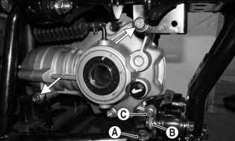
5.In order, tighten the lower frame/gear case bracket mounting nuts (A) to 35 ft-lb, lower lateral link nuts (B) to 40 ft-lb, and the gear case cap screw (C) to 20 ft-lb; then tighten the nuts on lower front and upper rear through-bolts to 38 ft-lb.
WC296A
6.Install the upper left lateral link and secure with a bolt and nut. Tighten to 40 ft-lb.
WC169A
7.Apply molybdenum grease to the splines of the axle couplers and install the axles into the gear case; then swing the knuckles to the rear and fit the bearing over the ends of the axles.
WC286
8.Connect the upper trailing arm and secure but do not tighten; then connect the lower lateral link and upper lateral links to the knuckle. Tighten the upper trailing arm cap screw and the lateral link bolts to 40 ft-lb.
WC282B
9.Install the hub/brake disc assemblies onto the axles and apply Loctite primer and red Loctite #277 to the axle threads. 10.Engage the hub nut into the Belleville washer on the convex side; then with the concave side of the washer directed toward the hub, install the nut and washer.
Keeping the nut and washer engaged, tighten the hub nut to 250 ft-lb.
WC303A
11.Install the brake calipers and secure with new “patchlock” cap screws. Tighten to 20 ft-lb. 12.Install the hub plate making sure it fits completely over the nut and lies flat against the hub.
WC317A
NOTE: If the hub plate cannot be fully installed due
to misalignment of the nut, tighten the nut until properly aligned and the plate is fully seated.
13.Install the wheels; then using a crisscross pattern, tighten the wheel nuts in 20 ft-lb increments to a final torque factor of 80 ft-lb. Install the hub caps. 14.Pour in the recommended gear case lubricant and check to ensure the lubricant is 1 inch below threads in fill/level hole. Install and tighten the fill/level plug to 16 ft-lb.
Hub
REMOVING 1.Secure the vehicle on a support stand to elevate the wheel; then remove the wheel and account for the hub plate.
WC240B
2.Remove the Belleville washer and hub nut securing the hub.

WC304
3.Remove the brake caliper.
WC606
4.Remove the hub assembly. 5.Remove the four cap screws securing the brake disc. CLEANING AND INSPECTING 1.Clean all hub components. 2.Inspect all threads for stripping or damage. 3.Inspect the brake disc (if applicable) for cracks or warping. 4.Inspect the hub for pits, cracks, loose studs, or spline wear. REPLACING WHEEL STUDS 1.Secure the hub in a suitable holding fixture and remove the brake disc (if applicable). 2.Drive the damaged stud out of the hub; then place the new stud into the hub and thread on an appropriate flange nut.
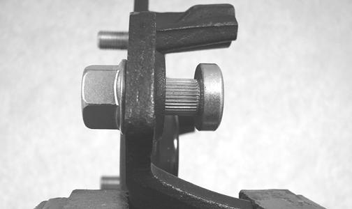
PR250
3.Using a socket and ratchet handle, tighten the nut until the stud is fully drawn into the hub.
PR252A
INSTALLING 1.Secure the brake disc to the hub with the four cap screws coated with red Loctite #271. Tighten to 15 ftlb. 2.Install the hub assembly onto the axle; then apply
Loctite primer and red Loctite #277 to the axle threads. Install the brake caliper and secure with new
“patch-lock” cap screws. Tighten to 20 ft-lb.
WC281
3.Engage the hub nut into the Belleville washer on the convex side; then with the concave side of the washer directed toward the hub, install the nut and washer.
Keeping the nut and washer engaged, tighten the hub nut to 250 ft-lb.
WC303A
4.Install the hub plate making sure it fits completely over the nut and lies flat against the hub.
WC317A
NOTE: If the hub plate cannot be fully installed due
to misalignment of the nut, tighten the nut until properly aligned and the plate is fully seated.
5.Install the wheel and using a crisscross pattern, tighten the wheel nuts in 20 ft-lb increments to a final torque factor of 80 ft-lb. 6.Remove the vehicle from the support stand.
Hydraulic Brake Caliper
! WARNING
Arctic Cat recommends only authorized Arctic Cat Wildcat dealers perform hydraulic brake service. Failure to properly repair brake systems can result in loss of control causing severe injury or death.
REMOVING/DISASSEMBLING 1.Secure the vehicle on a support stand to elevate the wheel; then remove the wheels of the brake to be serviced.
! WARNING
Never let brake fluid contact the eyes. Damage to the eyes will occur. Always wear appropriate protective safety goggles and latex gloves when handling brake fluid.
CAUTION
Brake fluid is highly corrosive. Do not spill brake fluid on any surface of the vehicle and do not reuse brake fluid.
NOTE: Whenever brake components are removed,
disassembled, or repaired where brake fluid is exposed to air, drain all fluid and replace with new DOT 4 brake fluid from an unopened container. Brake fluid readily absorbs moisture from the air significantly lowering the boiling point. This increases the chance of vapor lock reducing braking power and increasing stopping distance.
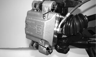
2.Remove the brake hose from the caliper and close-off the brake hose or place a suitable container under the end. 3.If a front brake caliper is being removed, remove the
E-clips on the inboard side of the caliper anchor bolts; then remove the anchor bolts from the knuckle.
WC611A
WC606
NOTE: If brake pads are to be returned to service,
do not allow brake fluid to contaminate them.
PR238
4.If a rear brake caliper is being removed, remove the cap screws securing the caliper holder to the knuckle; then remove the caliper. NOTE: The O-ring is used for shipping purposes
and provides no function in operation.
5.Remove the brake pads from the caliper.
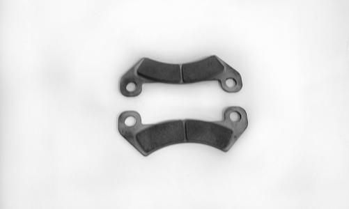
WC694 PR715
! WARNING
Make sure to hold the towel firmly in place or the piston could be ejected from the housing causing injury.
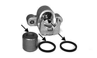
6.Using an appropriate seal removal tool, carefully remove the seals from the brake caliper housing; then remove four O-rings from the brake caliper housing noting the location of the different sized O-rings. Discard all seals, O-rings, and crush washers. CLEANING AND INSPECTING 1.Clean all caliper components (except the brake pads) with DOT 4 brake fluid. Do not wipe dry. 2.Inspect the brake pads for damage and excessive wear. NOTE: For measuring brake pads, see Periodic
Maintenance/Tune-Up.
3.Inspect the brake caliper housings for scoring in the piston bores, chipped seal ring grooves, or signs of corrosion or discoloration. 4.Inspect the piston surface for scoring, discoloration, or evidence of binding or galling. 5.Inspect the caliper holder or anchor bolts for wear or bending. ASSEMBLING/INSTALLING (Rear Brakes) 1.Install new seals into the brake caliper housing and apply a liberal amount of DOT 4 brake fluid to the cylinder bore of the housing, seals, and brake piston.
CAUTION
Make sure the seals are properly in place and did not twist or roll during installation.
PR717A
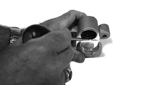
2.Press the piston into the caliper housing using hand pressure only. Completely seat the piston; then wipe off any excessive brake fluid.
PR711A
PR712
3.Apply high-temperature silicone grease (supplied with the O-ring kit) to the inside of the caliper holder bores and O-rings; then install the four O-rings into the caliper.
PR719C
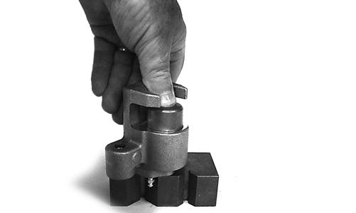
4.Install the caliper onto the caliper holder making sure the caliper and holder are correctly oriented.

PR239C
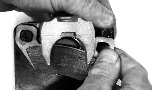
5.Making sure brake fluid does not contact the brake pads, compress the caliper holder toward the caliper and install the inner brake pad; then install the outer pad.
CAUTION
If brake pads become contaminated with brake fluid, they must be thoroughly cleaned with brake cleaning solvent or replaced with new pads. Failure to do so will result in reduced braking and premature brake pad failure.
PR238
PR239
6.Place the brake caliper assembly into position and secure with new “patch-lock” cap screws. Tighten the caliper to 20 ft-lb. 7.Place a new crush washer on each side of the brake hose fitting and install it on the caliper. Tighten to 20 ft-lb.
9.Install the wheel; then using a crisscross pattern, tighten the wheel nuts in 20 ft-lb increments to a final torque factor of 80 ft-lb. 10.Remove the vehicle from the support stand and verify brake operation. ASSEMBLING (Front Brakes) 1.Install new seals into the brake caliper housing and apply DOT 4 brake fluid to the cylinder bores and pistons. ! WARNING
Never use brake fluid from an open container or reuse brake fluid. Moisture-contaminated brake fluid could cause vapor build-up (expansion) during hard braking resulting in greatly increased stopping distance or loss of control leading to injury or death.
WC725A
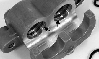
2.Install the pistons into the caliper seating them completely into the piston bore.
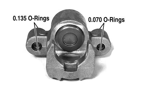
WC692
3.Using silicon grease, lubricate the O-rings and install into the anchor bolt bores making sure the correct size of O-rings are installed in the correct locations (thicker O-rings on bleed screw end of calipers). 4.Install the caliper and brake pads onto the brake disc and secure to the knuckle with the anchor bolts.
Tighten to 34 ft-lb.
WC606
5.Install the E-clips; then using new crush washers, connect the brake banjo fitting to the caliper and tighten to 20 ft-lb.
WC611A
WC609
6.Fill the reservoir; then bleed the brake system (see
Periodic Maintenance/Tune-Up.) 7.Making sure the hub nut locking plate is properly seated, install the wheel and tighten the lug nuts in 20 ft-lb increments to 80 ft-lb. MASTER CYLINDER ASSEMBLY NOTE: The master cylinder is a non-serviceable
component; it must be replaced as an assembly.
Removing 1.Slide a piece of flexible tubing over one of the wheel bleeder valves and direct the other end into a container. Remove the reservoir cover; then open the bleeder valve. Allow the brake fluid to drain until the reservoir is empty.
2.Remove the cotter pin and pivot pin from the yoke; then remove two cap screws and flange nuts securing the master cylinder assembly to the frame.
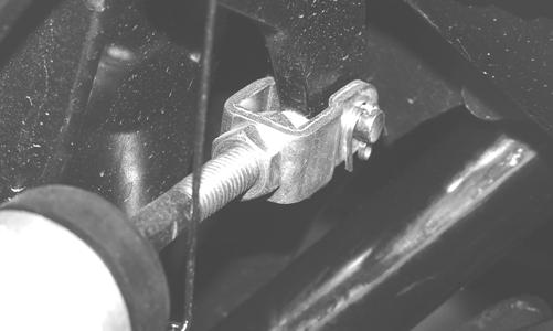
PR338
PR336
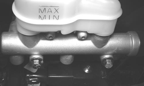
3.Remove the oil bolt securing the banjo-fittings to the master cylinder; then remove the master cylinder. Discard the three crush washers.
Inspecting 1.Inspect the master cylinder push rod and clevis for wear, bending, or elongation of clevis holes. 2.Inspect the push rod boot for tears or deterioration. 3.Inspect the reservoir for cracks and leakage. 4.Inspect the brake hose for cracks and deterioration and the condition of the banjo-fittings. Installing 1.Place the master cylinder into position; then using three new crush washers, secure the two banjo-fittings to the master cylinder. Tighten to 20 ft-lb. 2.Secure the master cylinder assembly to the frame with two cap screws and two flange nuts. Tighten to 25 ftlb. 3.Install the pivot pin and secure with a new cotter pin. 4.Fill the master cylinder and bleed the brake system (see Hydraulic Brake System in Periodic Maintenance/Tune-Up). CAUTION
Brake fluid is highly corrosive. Do not spill brake fluid on any surface of the vehicle.
Troubleshooting
Problem: Power not transmitted from engine to wheels Condition Remedy
1. Rear axle shaft serration worn - broken 1.Replace shaft
Problem: Power not transmitted from engine to either front wheel Condition Remedy
1. Secondary drive - driven gear teeth broken 1.Replace gear(s) 2. Propeller shaft serration worn - broken 2.Replace shaft 3. Coupling damaged 3.Replace coupling 4. Coupling joint serration worn - damaged 4.Replace joint 5. Front drive - driven bevel gears broken - damaged 5.Replace gear(s) 6. Front differential gears/pinions broken - damaged 6.Replace gears - pinions 7. Front drive actuator not operating 7.Replace fuse - drive select switch - front drive actuator