20 minute read
Steering/Frame/Controls

The following steering components should be inspected periodically to ensure safe and proper operation.
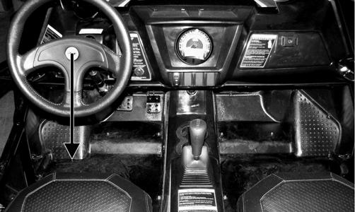
A.Steering wheel secure.
B.Steering has equal and complete full-left and fullright capability.
C.Steering sector mounting bolts tight.
D.Ball joints not worn, cracked, or damaged.
E.Tie rods not bent or cracked.
F.Knuckles not worn, cracked, or damaged.
G.Cotter pins not damaged or missing.
H.Steering wheel tilt locks securely. The frame and welds should be checked periodically for damage, bends, cracks, deterioration, broken components, and missing components.
Electronic Power Steering (EPS)
NOTE: Thoroughly troubleshoot the EPS system
prior to replacing the EPS assembly (see Electrical System) as there are several possible external causes for system failure.
REMOVING NOTE: Before removing the EPS, ensure the front
wheels and steering wheel are aligned to the front.
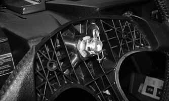
1.Remove two cap screws and two fender screws securing the grille and remove the grille.
WC081C
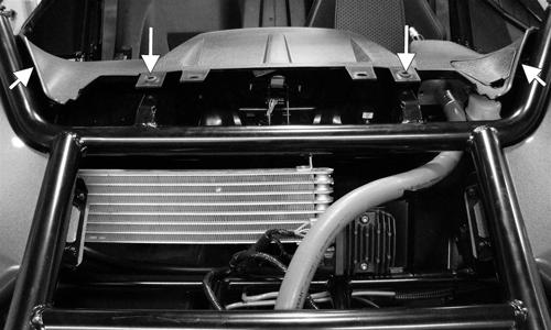
2.Remove two fender screws behind the headlights and two fender screws at the rear of the hood; then remove the hood.
WC241A
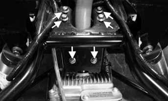
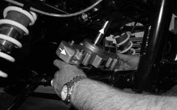
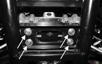
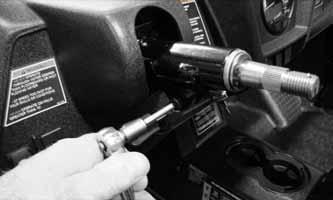
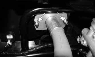
3.Unplug the two connectors from the EPS unit; then remove four cap screws and two lock nuts from the steering flex-shaft clamp bracket and clamp.
WC242A
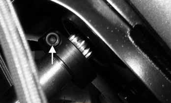
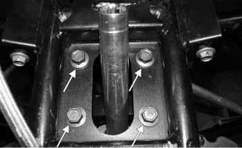
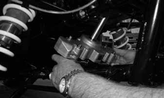
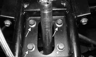
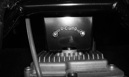
4.Remove the U-clamp; then remove the bracket. 5. Loosen the Allen-head cap screw securing the steering rack input coupler to the shaft; then remove four cap screws securing the EPS mounting bracket to the frame.
WC242A
WC245A
WC246A
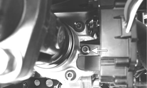
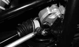
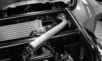
6.Remove the mounting screw securing the brake line support bracket to the EPS mounting bracket. 7.Remove the steering flex-shaft support bracket; then slide the EPS unit upwards and to the rear until clear of the steering rack input coupler.
WC247A
8.Remove the steering flex-shaft coupler from the EPS unit; then maneuver the assembly past the brake hoses and out of the vehicle.
WC253A
9.Remove the four cap screws securing the EPS mounting bracket to the EPS unit. NOTE: No repairs are authorized on the EPS assem-
bly and it must be replaced as a complete assembly.
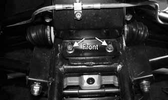
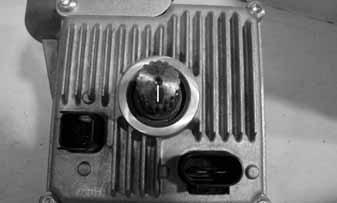
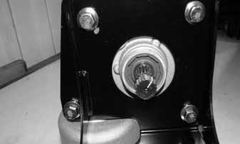
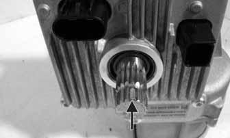
INSTALLING 1.Install the EPS mounting bracket onto the EPS unit and secure with the four cap screws. Tighten to 35 ftlb. 2.Mark the ends of the EPS input and output shafts to correspond with the flat-splined segment; then align the flat-splined segment of the output shaft with the slot in the rack input coupler and install the EPS into the vehicle.
WC254A
WC249A
3.Rock the EPS assembly to seat the splines and mounting bracket.
WC250A
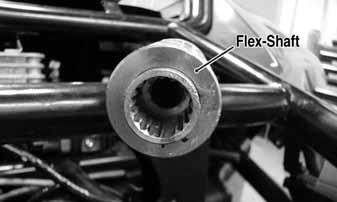
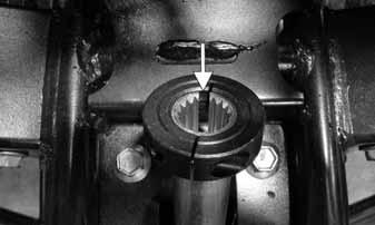
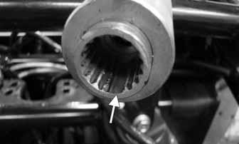
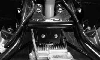
4.Secure the mounting bracket to the frame and tighten to 20 ft-lb. 5.Install the steering flex-shaft coupler onto the EPS input shaft aligning the flat-splined segment of the shaft to the slot in the coupler.
WC251A
WC252A
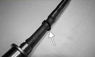
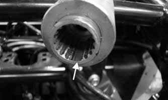
NOTE: The flex-shaft coupler must engage com-
pletely covering the majority of the splines of the input shaft.
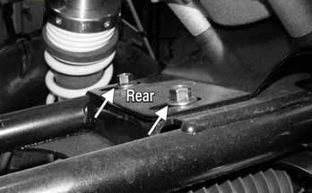
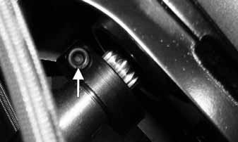
6.Attach the brake line support to the mounting bracket and tighten securely. 7.Tighten the input coupler clamp cap screw to 7 ft-lb.
WC244A
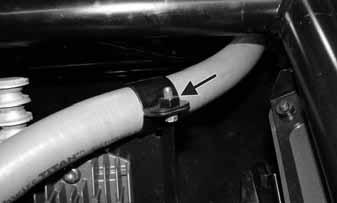
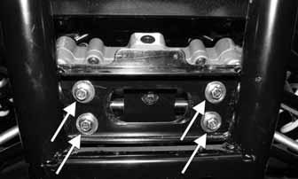
8.Install the flex-shaft clamp bracket and four cap screws loosely installed; then install the U-clamp and secure with two lock-nuts. Tighten the U-clamp lock nuts to 7 ft-lb and the lower bracket cap screws to 20 ft-lb. 9.Install the upper steering flex-shaft hold-down strap and tighten the cap screw to 50 in.-lb.
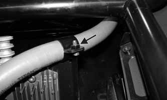
WC247A
10.Connect the two electrical connectors and check EPS operation. 11.Install the hood and grille.
Rack and Pinion Assembly
REMOVING 1.Remove the hood and grille; then remove the EPS assembly (see Electronic Power Steering (EPS) in this section). 2.Remove the front differential assembly (see Drive
System - Front Differential). 3.Remove the cotter pins and nuts securing the tie rods to the steering rack.
WC259
4.Remove four cap screws securing the upper mounting bracket to the frame and remove the bracket. INSPECTING 1.Inspect the input shaft splines for excessive wear or signs of misalignment. 2.Inspect the slide mechanism for pitting, excessive wear, or worn bushings. 3.Rotate the input shaft from center to full left and right checking for any binding or catching. 4.Check for loose cap screws on rack and pinion housing. 5.Check for seal damage or lubricant leaks. NOTE: The steering assembly (rack and pinion) is
not repairable and must be replaced as an assembly; however, the tie rods and boots are replaceable.
INSTALLING 1.Place the rack and pinion assembly into the frame and guide the steering input shaft up through the shaft opening; then rotate the assembly forward and into position on the front mounting bracket.
WC278A
5.Remove four cap screws securing the rack and pinion assembly to the frame; then rotate the rack and pinion assembly to the rear and out of the frame from either side.
WC260A WC279A
2.Secure the bracket to the frame with four cap screws and tighten to 20 ft-lb.
WC260A
3.Install the upper mounting bracket in the frame and secure with new “patch-lock” cap screws. Tighten to 20 ft-lb.
WC278A
4.Connect the tie rods to the steering rack and secure with the nuts (threads coated with red Loctite #271).
Tighten to 55 ft-lb and install new cotter pins.
WC257
5.Install the front differential assembly (see under Drive
System - Front Differential). 6.Install the EPS assembly (see Electronic Power Steering (EPS) in this section). 7.Install the hood and grille.
Steering Wheel
REMOVING 1.Remove the steering wheel cover; then match mark the steering shaft and steering wheel. NOTE: Any time steering components are disas-
sembled, all connecting components should be marked for proper alignment during assembling.
2.Remove the hairpin clip from the steering shaft; then remove the nut securing the steering wheel and remove the steering wheel.
WC321
INSPECTING 1.Inspect the steering wheel for cracks, missing padding, or broken spokes. 2.Inspect the splines for wear. 3.Check that the steering wheel is not bent. INSTALLING 1.Install the steering wheel aligning the two match marks; then apply a drop of red Loctite #271 to the threads of the nut and secure the steering wheel.
Tighten to 25 ft-lb. NOTE: If a new steering wheel is being installed,
mark the wheel as close as possible to the old wheel mark; then check for proper positioning with the front wheels straight forward.
2.Install the hairpin clip on the steering shaft. NOTE: If the hole in the steering shaft does not
align with the slots in the nut, tighten the nut slightly until the next slot aligns with the hole.
WC321
Steering Shaft
REMOVING 1.Remove the steering wheel (see Steering Wheel in this section). 2.Remove the hood and grille (see Hood in this section).
WC330
4.Remove four upper dash mounting screws and block the dash to the rear.
WC329A
5.Remove the steering shaft housing support hold-down strap; then remove the U-clamp from the lower steering shaft support.
WC247A WC328A
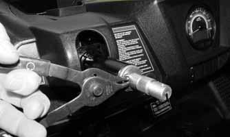
6.Remove the steering shaft from the EPS by pulling straight away from the input shaft.
WC335
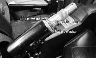
7.Remove the upper and lower snap rings from steering shaft; then work the steering shaft out of the upper steering support housing and remove from the vehicle.
Account for a flat washer and a wave washer.
WC326
INSPECTING 1.Check that the steering flex-shaft rotates freely in the housing with no sticking or binding. 2.Check the splines for wear or any signs of twisting. 3.Check the housing for cuts, cracks, or kinks. 4.If the assembly is serviceable, remove the flex-shaft and lubricate with the appropriate lubricant; then reinstall in the housing. INSTALLING 1.Making sure the lower snap ring is loosely on the steering shaft but not installed, slide the shaft into the upper steering support housing.
WC341A
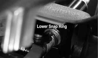
2.From under the dash, install the lower snap ring onto the steering shaft.
WC337A
3.Install the wave washer and flat washer onto the upper steering shaft; then install the upper snap ring.
WC339A
5.Install the steering flex-shaft coupler onto the EPS input shaft aligning the flat-splined segment of the shaft to the slot in the coupler; then install the Uclamp on the lower sheering shaft housing and secure with two nuts. Tighten to 7 ft-lb.

WC251A
WC252A
WC242
6.Install the upper steering flex-shaft hold-down strap and secure with the cap screw. Tighten to 50 in.-lb.
WC247A
7.Install the upper tilt-steering link pivot bolt and tighten to 10 ft-lb; then install the steering wheel (see
Steering Wheel in this section). 8.Remove the block and secure the upper dash screws; then install the hood and grille (see Hood in this section).
Steering Knuckles
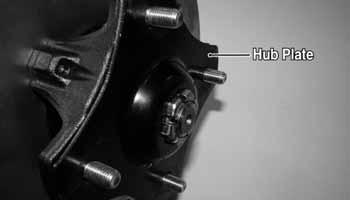
REMOVING AND DISASSEMBLING 1.Secure the vehicle on a support stand to elevate the wheel; then remove the wheel and account for the hub plate. 2.Remove the nut and Belleville washer securing the hub. 3.Remove the brake caliper. 4.Remove the hub assembly. 5.Remove the cotter pin from the tie rod end and remove the tie rod end from the knuckle. 6.Remove the upper cap screw securing the ball joint in the knuckle.

WC271
7.Tap the ball joint end out of the knuckle; then slide the axle out of the knuckle. 8.Remove the cap screw securing the lower ball joint to the knuckle and remove the knuckle. 9.Remove the snap ring securing the bearing in the knuckle; then press the bearing out of the knuckle. CLEANING AND INSPECTING 1.Clean all knuckle components. 2.Inspect the bearing for pits, scoring, rusting, or premature wear. 3.Inspect the knuckle for cracks, breaks, or galling of the bearing surface. ASSEMBLING AND INSTALLING 1.Using a suitable press and driver, press the bearing into the knuckle until firmly seated; then install the snap ring. 2.Install the knuckle to the lower ball joint and secure with a new “patch-lock” cap screw. Tighten to 35 ftlb. 3.Slide the axle into the knuckle; then install the upper ball joint and secure with a new “patch-lock” cap screw. Tighten to 35 ft-lb.
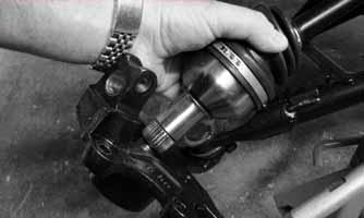
WC272
WC271
4.Install the tie rod end and secure with the nut (coated with red Loctite #271). Tighten to 55 ft-lb; then install a new cotter pin and spread the pin. NOTE: During assembling, new cotter pins should
be installed.
5.Install the hub assembly onto the axle; then apply
Loctite primer and red Loctite #277 to the axle threads.
WC281
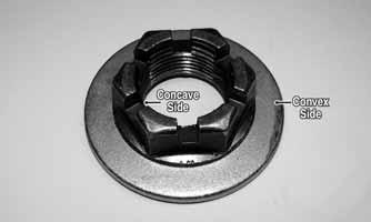
6.Engage the hub nut into the Belleville washer on the convex side; then with the concave side of the washer directed toward the hub, install the nut and washer.
Keeping the nut and washer engaged, tighten the hub nut to 250 ft-lb.
WC303A
7.Secure the brake caliper to the knuckle with the two anchor bolts and E-clips. Tighten to 34 ft-lb.
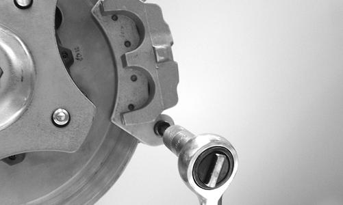
WC606
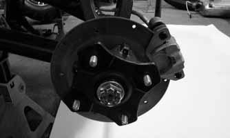
8.Install the hub plate making sure it fits completely over the nut and lies flat against the hub.

WC317A
NOTE: If the hub plate cannot be fully installed due
to misalignment of the hub nut, tighten the nut until properly aligned and plate is fully installed.
9.Install the wheel; using a crisscross pattern, tighten the wheel nuts in 20 ft-lb increments to a final torque factor of 80 ft-lb. 10.Remove the vehicle from the support stand.
Checking/Adjusting Front Wheel Alignment
NOTE: All measurements and adjustments must be
made with the vehicle unloaded.
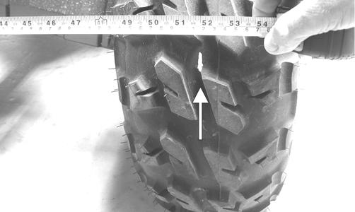
Mark the center-line of the front tires at the front and rear of the tire; then using a tape measure, measure and record the distance between the marks at the front and rear. The front measurement should be 6 mm (1/4 in.) greater than the rear measurement (toe-out).
PR087A
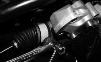
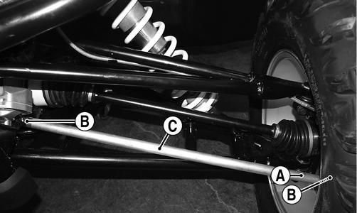
To adjust the wheel alignment, use the following procedure. 1.Center the steering wheel; then using an open-ended wrench on the tie rod flat (A), loosen the inner and outer jam nuts (B) on both tie rods.
WC012A
WC110B
CAUTION
Always use a wrench to hold the tie rod ends when loosening or tightening the jam nuts or damage to the boots could occur.
2.Turn the left-side and right-side tie rods in equal increments to achieve the proper toe-out; then tighten the jam nuts to 10 ft-lb.
Hood
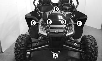
REMOVING 1.Remove two fender screws (A) and two machine screws (B) with washers from the grille and remove the grille.
WC549B
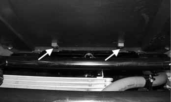
2.Remove two side fender screws (C), one on left and one on right located above and behind the headlight assemblies. 3.Reach up through the front fender wells and remove two fender screws (D) from the rear of the hood and remove the hood. INSTALLING 1.Lay the hood in place on the frame; then install the rear fender screws (D).
WC549B
2.Install the two side fender screws (C); then place the grille on the vehicle and install the two machine screws (B) and fender screws (A). Tighten all fasteners securely.
Rear Body Panel
REMOVING 1.Remove the seats; then remove the machine screws securing the rear body panel to the frame and rear splash panel.
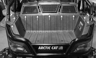
WC346A

WC347A
2.Remove the hose clamp from the gasoline filler neck and disconnect the filler hose.
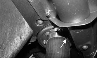
WC344A
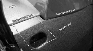
3.Lift the rear body panel off and remove forward between the ROPS uprights; then tape or plug the filler hose to prevent contamination of fuel or vapor escaping. INSTALLING 1.Place the rear body panel onto the vehicle making sure the outer front mounting tabs are located behind the splash panel.
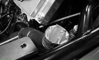
WC342A
2.Secure with the machine screws and tighten securely. 3.Remove the plug or tape from the gas filler hose and connect the hose to the gasoline filler neck and secure with the hose clamp. Tighten securely.
Accelerator Pedal
REMOVING Dislodge the throttle cable holding grommet from the actuator arm; then remove two torx-head screws and nuts securing the accelerator pedal assembly to the splash panel and remove the accelerator pedal.

PR709
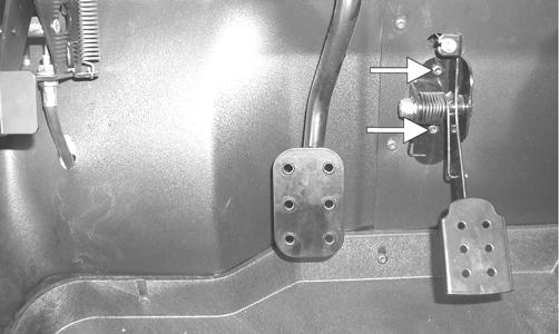
INSTALLING Align the mounting holes with the holes in the splash panel and secure with the two torx-head screws and nuts; then snap the throttle cable holding grommet into the actuator arm.
Shift Lever
REMOVING
1.Remove the seats; then remove the battery cover and shift lever handle. 2.Remove the center console leaving the shift lever boot in the console. 3.Remove the nut from the shift cable pivot bolt; then remove the four machine screws from the shift lever axle mounting and remove the shift lever.
WC348A
INSTALLING 1.Place the shift lever into position and secure with the four machine screws (threads coated with blue Loctite #243). Tighten to 20 ft-lb. 2.Connect the shift cable to the shift arm with the pivot bolt and tighten the nut to 8 ft-lb. 3.Check shift cable adjustment (see Periodic Maintenance/Tune-Up - Shift Lever/Shift Cable); then install the center console. Tighten the machine screws securely. 4.Install the shift lever handle onto the shift lever and tighten the jam nut with the handle correctly aligned. 5.Install the battery cover and seats.
Shift Cable
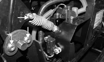
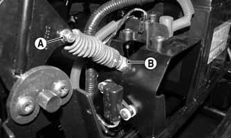
REMOVING 1.Remove the seats, battery cover, and center console. 2.Remove the nut (A) from the shift arm pivot bolt: then loosen the jam nut (B) and lift the cable upward out of the mounting bracket slot.
WC348B
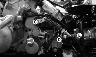
3.Remove the E-clip (C); then loosen jam nut (D) and slide the cable (E) out of the mounting bracket.
WC178B
4.From under the vehicle, mark any cable tie locations; then remove the shift cable from the vehicle. 5.If the shift cable is to be replaced, accurately measure and record the distance between the adjuster nuts (nuts opposite the jam nuts). INSTALLING 1.Using the measurements from the existing cable, adjust the adjuster nuts to the same length. NOTE: The shift cable will have to be adjusted, but
using the existing measurements will give a close starting point.
2.From under the vehicle, thread the new cable into position. Do not tie cable tie points yet. 3.Set the upper cable housing end into the mounting bracket and finger tighten jam nut (B); then connect the cable to the shift arm pivot bolt and secure with the nut (A). Tighten the nut to 8 ft-lb.
WC348B
4.Place the lower cable housing end into the mounting bracket on the engine and finger tighten jam nut (D); then connect cable (E) to the shift arm and install the E-clip (C).
WC178B
5.Install any necessary cable ties as marked during removal; then adjust the shift cable (see Periodic Maintenance/Tune-Up - Shift Lever/Shift Cable). After cable is properly adjusted, tighten the jam nuts to 20 ft-lb. 6.Install the center console, battery cover, and seats.
LCD Gauge/Indicator Lights/Dash Switches
REPLACING 1.Remove the hood and grille (see Hood in this section). 2.Remove the four screws securing the upper dash to the frame. 3.Remove the nuts securing the gauge assembly to the dash; then unplug the multi-pin connector and remove the gauge from the vehicle. 4.Place the new gauge into the dash panel opening; then place the gauge holder over the mounting screws and secure with the nuts. 5.Plug the multi-pin connector into the gauge; then turn the ignition switch to the ON position and check gauge functions. 6.Install the dash and secure with the four screws; then install the hood and grille (see Hood in this section).
Exhaust System
REMOVING MUFFLER 1.Remove the four exhaust springs at the muffler/ exhaust pipe juncture.
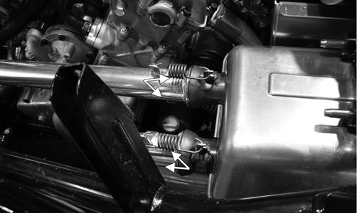
WC153A
2.Slide the muffler assembly clear of the holder pins. INSPECTING MUFFLER 1.Inspect muffler externally for cracks, holes, and dents. 2.Inspect the muffler internally by shaking the muffler back and forth and listening for rattles or loose debris inside the muffler. NOTE: For additional details on cleaning the muf-
fler/spark arrester, see Periodic Maintenance/TuneUp.
INSTALLING MUFFLER 1.Place the muffler onto the holder pins and slide into position. 2.Secure the muffler to the exhaust pipe with the two exhaust springs.
Cargo Box
REMOVING
1.Remove the rear body panel (see Rear Body Panel in this section).
WC345A
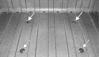
INSTALLING 1.Set the cargo box into position on the cargo box mounts; then secure with the four fender screws.
Tighten securely. 2.Install the rear body panel (see Rear Body Panel in this section).
Seats
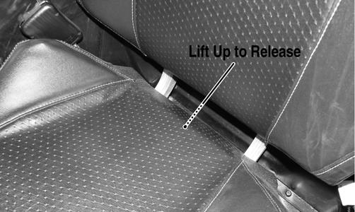
REMOVING/INSTALLING 1.To remove a front seat, pull the seat lock lever up.
Raise the rear of the seat and tilt it forward.
WC017A
2.To install a front seat, slide the front of the seat into the seat retainers and push down firmly on the rear of seat. The seat should automatically lock into position. 3.To remove a rear seat, remove two flange nuts securing the seat support to the floor; then remove the seat.
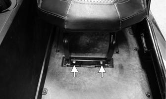
WC722A
4.To install a rear seat, place into position with the seat support engaging the floor bolts; then install the flange nuts and tighten securely.
Troubleshooting
Problem: Handling too heavy or stiff Condition Remedy
1. Front wheel alignment incorrect 1.Adjust alignment 2. Lubrication inadequate 2.Lubricate appropriate components 3. Tire inflation pressure incorrect 3.Adjust pressure 4. Tie rod ends seizing 4.Replace tie rod ends 5. Linkage connections seizing 5.Repair - replace connections 6. EPS malfunction 6.Replace EPS
Problem: Steering oscillation Condition Remedy
1. Tires inflated unequally 1.Adjust pressure 2. Wheel(s) wobbly 2.Replace wheel(s) 3. Wheel hub cap screw(s) loose - missing 3.Tighten - replace cap screws 4. Wheel hub bearing worn - damaged 4.Replace bearing 5. Tie rod ends worn - loose 5.Replace - tighten tie rod ends 6. Tires defective - incorrect 6.Replace tires 7. A-arm bushings damaged 7.Replace bushings 8. Bolts - nuts (frame) loose 8.Tighten bolts - nuts
Problem: Steering pulling to one side Condition Remedy
1. Tires inflated unequally 1.Adjust pressure 2. Front wheel alignment incorrect 2.Adjust alignment 3. Wheel hub bearings worn - broken 3.Replace bearings 4. Frame distorted 4.Repair - replace frame 5. Shock absorber defective 5.Replace shock absorber
Problem: Steering impaired Condition Remedy
1. Tire pressure too high 1.Adjust pressure 2. Steering linkage connections worn 2.Replace connections 3. Cap screws (suspension system) loose 3.Tighten cap screws
Problem: Tire wear rapid or uneven Condition Remedy
1. Wheel hub bearings worn - loose 1.Replace bearings 2. Front wheel alignment incorrect 2.Adjust alignment
Problem: Steering noise Condition Remedy
1. Caps screws - nuts loose 1.Tighten cap screws - nuts 2. Wheel hub bearings broken - damaged 2.Replace bearings 3. Lubrication inadequate 3.Lubricate appropriate components
Problem: Rear wheel oscillation Condition Remedy
1. Rear wheel hub bearings worn - loose 1.Replace bearings 2. Tires defective - incorrect 2.Replace tires 3. Wheel rim distorted 3.Replace rim 4. Wheel hub cap screws loose 4.Tighten cap screws 5. Rear suspension lateral link bushing worn 5.Replace bushing 6. Trailing arm bushings worn 6.Replace bushings or link 7. Rear suspension lateral link loose 7.Tighten nut or replace