16 minute read
Fuel/Lubrication/Cooling

SPECIAL TOOLS A number of special tools must be available to the technician when performing service procedures in this section. Refer to the current Special Tools Catalog for the appropriate tool description.
Description p/n
Oil Pressure Test Kit 0644-495 Tachometer 0644-275
NOTE: Special tools are available from the Arctic
Cat Service Department.
Electronic Fuel Injection
! WARNING
Whenever the gasline hoses are removed (other than for pressure testing), the battery must be disconnected to prevent inadvertent activation of the electronic fuel pump.
! WARNING
Whenever any maintenance or inspection is performed on the fuel system during which there may be fuel leakage, there should be no welding, smoking, open flames, etc., in the area.
TROUBLESHOOTING 1.Verify that the electric fuel pump is operating by listening for a “whirring” sound for approximately three seconds after the ignition switch is turned to the ON position. If no sound can be heard, see Fuel Pump/
Fuel Level Sensor in this section. 2.Check for a flashing Malfunction Indicator Light (MIL) on the LCD. If the light is flashing, see EFI
Diagnostic System in Electrical System. 3.Make sure there is sufficient, clean gas in the gas tank. 4.Verify that the battery is sufficiently charged to crank the engine over at normal speed. 5.Check the air filter housing and air filter for contamination. Clean or replace as necessary (see Periodic
Maintenance/Tune-Up). REMOVING THROTTLE BODY 1.Turn the ignition switch to the OFF position; then remove the ignition switch key. 3.Remove the rear body panel; then remove the cargo box. 4.Remove the two screws securing the heat shield to the radiator/cooling fan assembly.
! WARNING
Do not turn the ignition switch to the ON position with the hoses removed. Gasoline will be pumped by the electric fuel pump causing a safety hazard.
WC351B
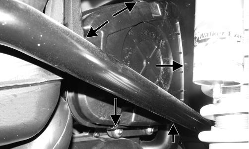
5.Remove the two upper radiator support mounting screws; then, while holding the heat shield away from the radiator, tip the radiator back and secure with an appropriate holding strap such as a tarp strap.
WC212
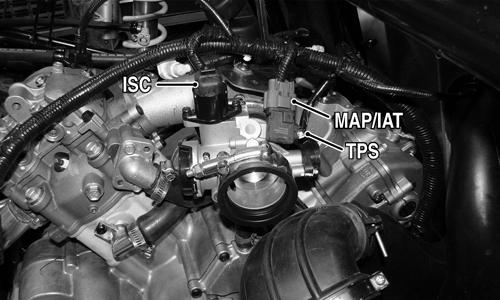
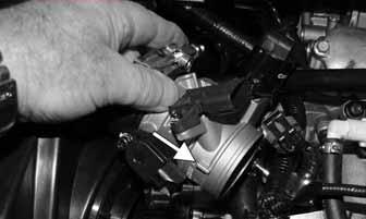
6.Remove the air filter housing strap. Loosen the air filter to throttle body clamp and pull the air filter assembly away from the throttle body; then disconnect the
ISC, MAP/IAT, and TPS connectors.
WC206B
7.Loosen the throttle body to intake clamp and remove the throttle body from the intake boot; then remove the screw from the throttle arm cover and disconnect the throttle cable from the throttle body.
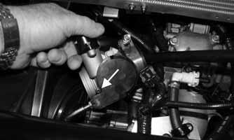
WC215A
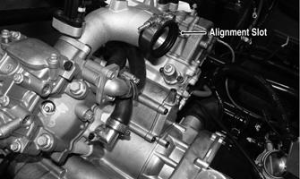
INSTALLING THROTTLE BODY 1.Connect the throttle cable to the throttle arm; then install the throttle cable housing to the throttle body and secure the throttle arm cover with the screw. 2.Make sure the alignment tab on the throttle body aligns with the slot in the intake boot and install the throttle body fully into the boot. Tighten the clamp to 30 in.-lb.
WC216A
WC164A
3.Install the wire connectors on the TPS, MAP/IAT, and
TPS; then place the air filter outlet into the throttle body boot and tighten the clamp to 30 in.-lb. Install the air filter housing strap.
WC206B
4.Remove the holding strap and move the radiator back into position and secure with the mounting screws.
Tighten securely. 5. Secure the heat shield and rear coil to the radiator, then install the cargo box. 6.Install the rear body panel and secure with the appropriate fasteners; then connect the negative battery cable and install the battery cover and seats.
Gas Tank
! WARNING
Whenever any maintenance or inspection is made on the fuel system during which there may be fuel leakage, there should be no welding, smoking, open flames, etc., in the area.
REMOVING 1.Remove the seats and battery cover; then disconnect the negative battery cable. 2.Remove the rear body panel and cap off or tape the gas filler hose. 3.Remove the cargo box; then disconnect the tail/brakelight connectors and the fuel pump/fuel level sensor connector. 4.Remove the exhaust pipe to muffler springs and remove the muffler. 5.Pry the wiring harness anchors out of the cargo box supports and mark any wire tie locations; then set the harness out of the way.
6.Remove the cargo box supports and the heat shield; then wrap a shop cloth around the gas line connector to catch any fuel spray and disconnect from the fuel pump. 7.Remove the gas tank hold-down bracket and remove the gas tank. INSTALLING
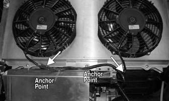
1.Place the gas tank into position on the cradle and secure with the hold-down bracket. Tighten the fasteners until the bracket is snug on the tank but not distorting it. 2.Place the heat shield into position; then install the cargo box supports and start but do not tighten all fasteners. After all fasteners are started, tighten securely. 3.Press the wiring harness anchors into the proper locations on the cargo supports and secure nylon ties where removed; then connect tail/brakelight connectors and fuel pump//fuel level connector.
! WARNING
Whenever any maintenance or inspection is made on the fuel system during which there may be fuel leakage, there should be no welding, smoking, open flames, etc., in the area.
WC179B
4.Install the muffler and secure with the four springs. 5.Install the cargo box; then install the rear body panel. 6.Connect the negative battery cable and install the battery cover; then set the seats in and lock into position.
Gas/Vent Hoses
Replace the gas hose every two years. Damage from aging may not always be visible. Do not bend or obstruct the routing of the vent hoses. Make certain the vent hoses are securely connected and the opposite ends are always open.
Oil Filter/Oil Pump
NOTE: Whenever internal engine components wear
excessively or break and whenever oil is contaminated, the oil pump should be replaced.
TESTING OIL PUMP PRESSURE NOTE: The engine must be warmed up to operating
temperature (cooling fan cycling) for this test.
1.Remove the oil hose from the fitting nearest the oil filter base.

WC222A
2.Using a suitable “T” fitting, connect Oil Pressure Test
Kit to the oil fitting and hose. Tighten all clamps securely. NOTE: Some oil seepage may occur when installing the
oil pressure gauge. Wipe up oil residue with a cloth.
3.Place the transmission in park and start the engine.
Allow the engine to warm up to operating temperature (with cooling fans cycling). 4.Set the speedometer/tachometer to RPM. With the engine running at 3000 RPM, the pressure gauge must show 1.05-1.2 kg/cm2 (15-17 psi). 5.Remove the test kit from the vehicle and install the oil hose. Tighten the clamps securely. NOTE: If oil pressure is lower than specified, check
for an oil leak, clogged oil filter, or defective oil pump.
NOTE: If oil pressure is higher than specified, check
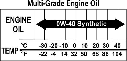
for too heavy engine oil weight (see General Information), clogged oil passage, or improper installation or type of the oil filter.
REMOVING/DISASSEMBLING 1.Remove the oil pump from the engine (see Center
Crankcase Components in Engine/Transmission). 2.Remove oil pump components from crankcase. CLEANING AND INSPECTING 1.Clean all oil-pump components. 2.Inspect the rotors for scoring and gouges. 3.Inspect the driveshaft and driven sprocket for damage. 4.Inspect the crankcase for scoring, cracks, or damage. ASSEMBLING/INSTALLING 1.Place the rotors into the crankcase making sure the dowel pin is in the groove of the rotor. 2.Place the cover onto the crankcase.
Oil Cooler
REMOVING 1.Remove the hood. 2.Loosen the clamps securing the oil hoses to the oil cooler; then place an absorbent towel under the connection and remove the hoses. 3.Remove the cap screws from the oil cooler mountings and remove the oil cooler. CLEANING AND INSPECTING 1.Prior to washing, inspect the oil cooler for signs of leaks such as oily dirt build-up. 2.Wash the cooling fins using a garden hose and hot, soapy water and a soft brush. 3.Inspect all mounting brackets and the oil inlet and outlet for cracks or bends. INSTALLING 1.Place the oil cooler into position and secure with the existing hardware. Tighten securely. 2.Connect the oil hoses and secure with the hose clamps. Tighten securely. 3.Install the hood.
Liquid Cooling System
When filling the cooling system, use premixed Arctic Cat Antifreeze. While the cooling system is being filled, air pockets may develop; therefore, open the bleed screw on the upper coolant pipe or the thermostat housing to allow air to bleed from the cooling system. When clear coolant (no bubbles) is present, tighten the bleed screw securely; then fill the cooling system to the bottom of the stand pipe in the radiator neck. Run the engine for five minutes after the initial fill, shut the engine off, and then “top-off” the cooling system to the bottom of the stand pipe in the radiator neck.
CAUTION
After operating the vehicle for the initial 5-10 minutes, stop the engine, allow the engine to cool down, and check the coolant level. Add coolant as necessary.
Radiator
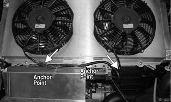
REMOVING 1.Remove the seats. 2.Remove the rear body panel (see Steering/Frame/Controls) and cap the gas tank fill hose; then remove the cargo box (see Steering/Frame/Controls). 3.Disconnect the cooling fan electrical connectors and pry the harness anchors from the radiator frame and coil bracket.
WC180B
4.Remove the screws securing the heat shield to the radiator frame and disconnect the coil primary connector; then remove the spark plug wire from the spark plug.
WC357A
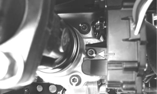
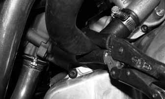
5.Clamp the coolant hoses off; then loosen the coolant hose clamps.
WC192
WC193
NOTE: Note the routing of hoses and location of
any ties used to secure hoses to frame.
6.Remove the four fasteners securing the radiator to the frame weldments.
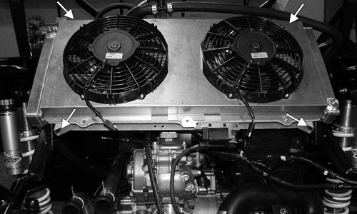
WC197A
7.Place absorbent towels under the hose connections; then remove the hoses. 8.Remove the radiator/fan assembly from the vehicle and drain remaining coolant from the radiator into a suitable container. NOTE: If the radiator is to be replaced, transfer the
cooling fans, coolant hoses, coil, and attaching hardware to the replacement radiator.
INSTALLING 1.Place the assembled radiator/fan assembly into position in the frame weldments and loosely install the cap screws; then route the coolant hoses as noted when removing and secure with the appropriate hose clamps. Tighten the mounting cap screws securely. 2.Connect the spark plug wire and primary coil connector; then secure the heat shield to the radiator frame. 3.Connect the cooling fan connectors; then press the wiring harness anchors into the appropriate locations.
WC180B
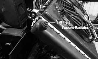
4.Install the cargo box (see Steering/Frame/Controls). 5.Pour the proper mixture and quantity of coolant into the radiator filler loosening the radiator cap to allow air to escape while filling.
WC354A
6.Start the engine and allow it to warm up while checking for leaks; then shut the engine off and check coolant level. Adjust as required. 7.Remove the cap from the gas tank fill hose and install the rear body panel and secure with the appropriate fasteners. Tighten the gas tank fill hose clamp securely.
WC186
8.Install and lock the seats into position.
Thermostat
REMOVING NOTE: The thermostat is located in a housing in-
line with the upper radiator hoses under the radiator/ fan assembly.
1.Clamp off the coolant hoses and place an absorbent towel under the thermostat. 2.Remove the four machine screws securing the thermostat housing together. Remove the thermostat and account for an O-ring. INSPECTING 1.Inspect the thermostat for corrosion or spring damage. 2.Using the following procedure, inspect the thermostat for proper operation.
A.Suspend the thermostat in a container filled with water.
B.Heat the water and monitor the temperature with a thermometer.
C.The thermostat should start to open at 71.0-86.0° C (160-187° F).
D.If the thermostat does not open, it must be replaced. 3.Inspect all coolant hoses, connections, and clamps for deterioration, cracks, and wear. NOTE: All coolant hoses and clamps should be
replaced every four years or 4000 miles.
INSTALLING 1.Place the thermostat and O-ring into the thermostat housing; then secure the thermostat housing together with the four machine screws. 2.Remove the clamp and fill the cooling system with the recommended amount of antifreeze. Check for leakage.
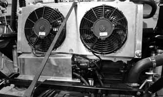
Fans
REMOVING 1.Remove the radiator (see Radiator in this section). 2.Remove the fan assembly from the radiator. INSTALLING 1.Position the fan assembly on the radiator; then secure with existing hardware. NOTE: The fan wiring must be directed downward.
2.Install the radiator (see Radiator in this section).
Water Pump
NOTE: The water pump is a non-serviceable compo-
nent. It must be replaced as an assembly.
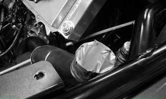
REMOVING 1.Clamp off and remove the coolant hoses from the water pump; then remove two cap screws securing the water pump to the crankcase.
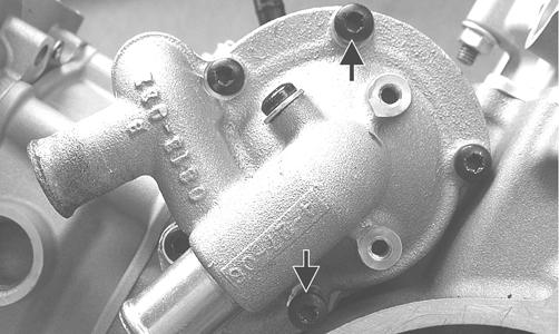
GZ230A
NOTE: Always use a large container and have suffi-
cient floor drying material available when draining the coolant in case of coolant spillage.
2.Remove the water pump from the engine. INSTALLING 1.Install a new O-ring onto the water pump and lightly coat with clean engine oil.
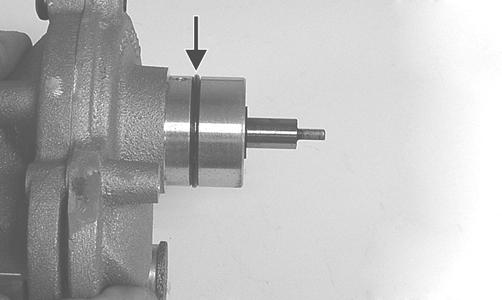
GZ252C
2.Install the water pump assembly onto the engine aligning the flat drive on the water pump to the slot in the driven gear shaft.
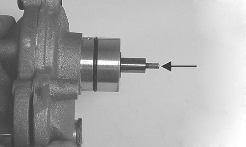
GZ252D
CAUTION

Do not force the water pump housing into the crankcase or sever engine damage may occur.
3.Secure the water pump with the two cap screws and tighten securely; then connect the coolant hoses and secure with hose clamps. Release the clamps used in removing. 4.Fill the cooling system with appropriate mixed coolant and install the radiator cap. 5.Start the engine and check for coolant leaks; then add coolant if necessary to proper level.
CAUTION
After operating the Wildcat for the initial 5-10 minutes, stop the engine, allow the engine to cool down, and check the coolant level. Add coolant as necessary.
Fuel Pump/Fuel Level Sensor
NOTE: Preliminary checks may be performed on
this component using the diagnostic mode on the LCD gauge (see EFI Diagnostic System in the Electrical System section).
The fuel pump and fuel level sensor are not serviceable components. If either component fails, it must be replaced. TESTING
1.Turn the ignition switch ON and listen for a momentary “whirring” sound of the pump building pressure.
If the sound is heard (10 seconds), no electrical checks are necessary. Turn the ignition switch OFF.
! WARNING
Whenever any maintenance or inspection is made on the fuel system during which there may be fuel leakage, there should be no welding, smoking, open flames, etc., in the area.
AT THIS POINT
Prior to removing the fuel pump, the following test should be performed to determine that removal is necessary.
! WARNING
Gasoline may be under pressure. Place an absorbent towel under the connector to absorb any gasoline spray when disconnecting.
FI092A
3.Turn the ignition switch to the ON position. The fuel pressure should build until the pump shuts off. Pressure should read 3.0 kg-cm2 (43 psi). 4.Check for any flashing DTC (Diagnostic Trouble
Code) on the digital gauge. A disconnected or faulty tilt sensor will cause the fuel pump not to run and a code to flash. 5.If the pump is not running, check the 10 amp FUEL fuse in the PDM under the passenger seat. Replace as necessary and check for fuel pump operation. 6.If fuse is OK, check the FUEL relay by swapping with another relay. If the pump runs, replace the FUEL relay. 7.If the pump still is inoperative, replace as follows. REMOVING 1.Remove the seats and battery cover; then disconnect the negative battery cable. 2.Remove the rear body panel and cargo box (see Steering/Frame/Controls); then plug or tape over the gas tank filler hose. NOTE: The power supply/wiring to the fuel pump
could be checked by reconnecting the battery negative cable and using a multimeter set to DC volts; then check for battery voltage by turning the ignition to ON and checking between the black and red wires. Disconnect the negative battery cable when finished.
3.Disconnect the fuel pump/fuel level sender connector; then wrap a shop towel around the gasline connector and disconnect the gasline from the fuel pump. 4.Mark the components for assembling purposes and remove the screws securing the fuel pump to the gas tank.
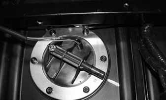
WC226
5.Carefully remove the fuel pump/fuel level sender assembly from the gas tank; then tape over the opening. INSPECTING
1.Inspect the fuel screen and blow clean with low pressure compressed air. 2.Move the float lever and check for free movement.
The float assembly should return to the lower position without force. If not, replace the fuel level sensor assembly. 3.Test the fuel level sensor by connecting a multimeter (A) to the fuel level sensor leads (B); then select
OHMS. The multimeter should show 5 ohms at full fuel position (C) and 95 ohms at empty fuel position (D). AT THIS POINT
If the pump has failed earlier test and must be replaced, proceed to INSTALLING.
ATV2116
NOTE: If readings are erratic, clean the resistor
wiper and resistor with clean alcohol and retest. If still not correct, replace the fuel level sensor.
4.To replace the fuel level sensor, use the following procedure.
A.Disconnect the two-wire connector (A); then press the fuel level sensor toward the top of the fuel pump to release it from the mounting slot (B).
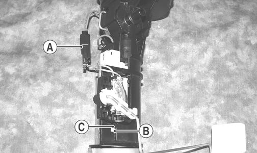
FI460A
B.Engage the tabs (C) of the fuel level sensor into the mounting slot (B) and press toward the bottom of the fuel pump to latch in place; then connect the two-wire connector (A). INSTALLING 1.Carefully place the fuel pump assembly into the gas tank referencing orientation marks made during removal.
WC226
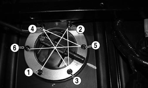
2.Secure the pump assembly with the mounting screws and tighten securely in a crisscross pattern.
WC226A
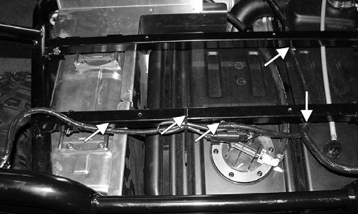
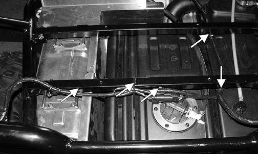
3.Connect the electrical connector and the gasline hose connector to the fuel pump; then press the wiring harness anchors into position and secure the cable ties as shown.
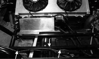
WC224A
4.Install the cargo box; then install the rear body panel and connect the gas tank filler hose and secure with the clamp. 5.Connect the negative battery cable and install the battery cover; then install the seats and lock in place.
Troubleshooting
Problem: Starting impaired Condition Remedy
1. Gas contaminated 1.Drain gas tank and fill with clean gas
Problem: Idling or low speed impaired Condition Remedy
1. TPS out of adjustment 1.Adjust TPS
Problem: Medium or high speed impaired Condition Remedy
1. High RPM “cut out” against RPM limiter 1.Decrease RPM speed