10 minute read
Suspension

The following suspension system components should be inspected periodically to ensure proper operation.
A.Shock absorber rods not bent, pitted, or damaged.
B.Rubber damper not cracked, broken, or missing.
C.Shock absorber body not damaged, punctured, or leaking.
D.Shock absorber eyelets not broken, bent, or cracked.
E.Shock absorber eyelet bushings not worn, deteriorated, cracked, or missing.
F.Shock absorber spring not broken or sagging.
Front Shock Absorbers
NOTE: Whenever a part is worn excessively,
cracked, or damaged in any way, replacement is necessary.
1.Clean the shock absorbers in parts-cleaning solvent. 2.Inspect each shock rod for nicks, pits, bends, and oily residue. 3.Inspect the springs, spring retainers, shock rods, shock bodies, and eyelets for cracks, leaks, and bends. INSTALLING 1.Install each shock absorber to the frame and A-arm with cap screws and nuts. Tighten all nuts to 29 ft-lb.
CAUTION
Do not tighten the nut beyond the recommended specification or the shock eyelet or mount WILL be damaged.
2.Remove the ATV from the support stand.
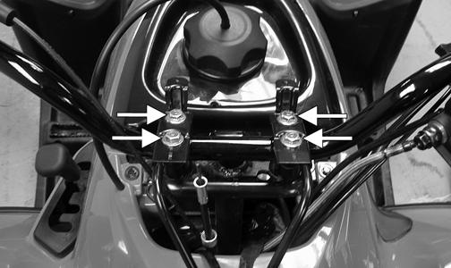
REMOVING 1.Secure the ATV on a support stand to elevate the wheels and to release load on the suspension.
2.Remove the cap screws and nuts securing each shock absorber to the A-arm and frame.
! WARNING
Make sure the ATV is solidly supported on the support stand to avoid injury.
TR009
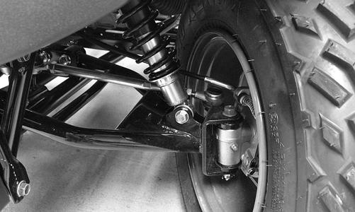
Rear Shock Absorber
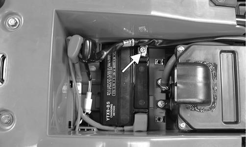
REMOVING 1.Secure the ATV on a support stand to elevate the wheels and to release load on the suspension.
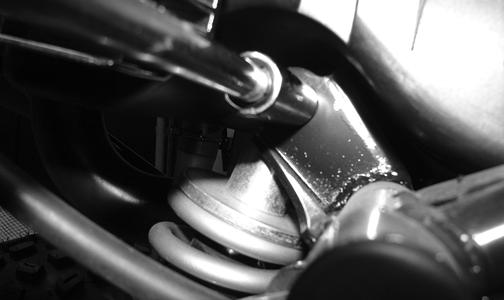
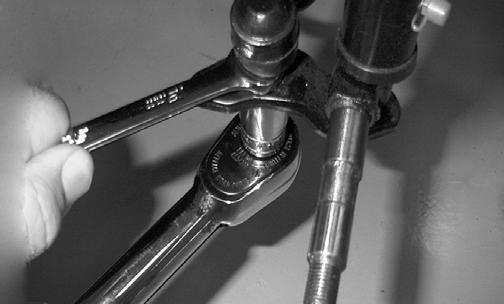
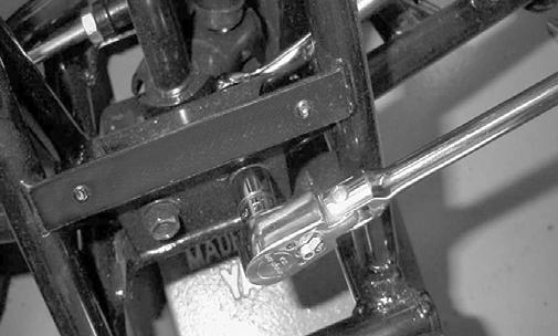
2.Remove the rear shield plate from the swing arm; then remove the lower shock mounting nut and cap screw. ! WARNING
Make sure the ATV is solidly supported on the support stand to avoid injury.
TR231
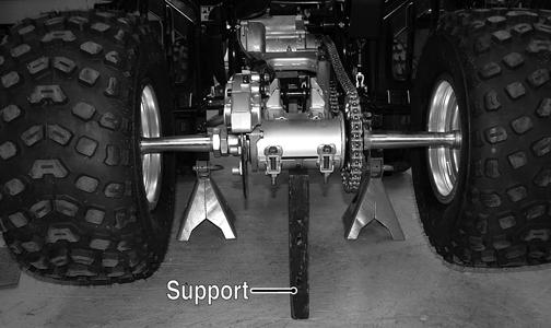
NOTE: Support the swing arm with a block of wood
or other support to allow removal of the cap screw.
KM555A
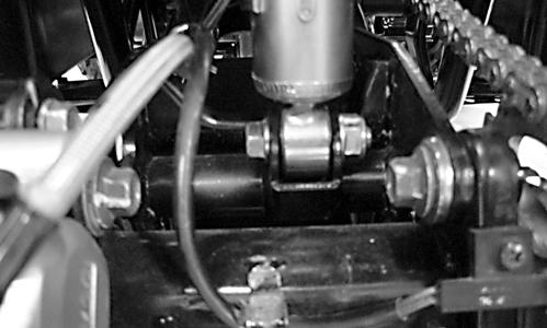
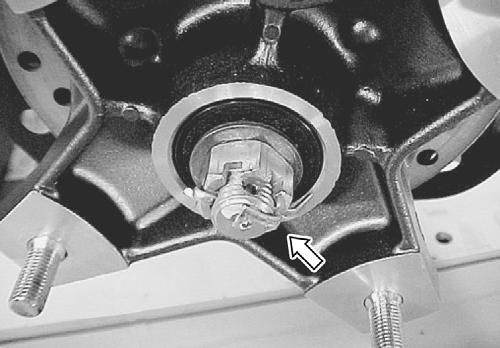
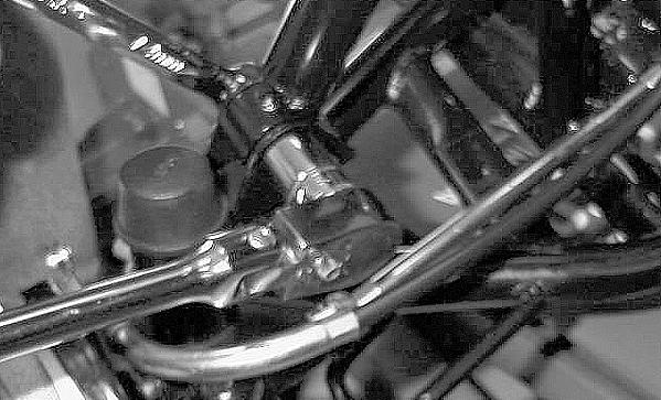
3.Remove the upper shock mounting nut and cap screw; then remove the shock absorber from the frame.
KM554
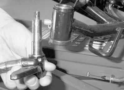
CLEANING AND INSPECTING 1.Clean the shock absorber in parts-cleaning solvent. 2.Inspect the shock absorber body, bottom stop, and rubber bushing for damage and leaking oil. If any defects are found, replace the shock absorber. 3.Inspect the spring, spring seat, and preload adjuster for damage or corrosion. If corrosion is present, clean with a fine wire brush and oil lightly. INSTALLING 1.Raise the swing-arm and place the shock absorber in position; then install the upper and lower cap screws and nuts. 2.Tighten the upper nut and the lower nut to 29 ft-lb. 3.Install the rear swing arm skid plate and four cap screws. Tighten securely.
Swing Arm
REMOVING AND DISASSEMBLING 1.Secure the ATV on a support stand to elevate the wheels and to release load on the suspension. ! WARNING
Make sure the ATV is solidly supported on the support stand to avoid injury.
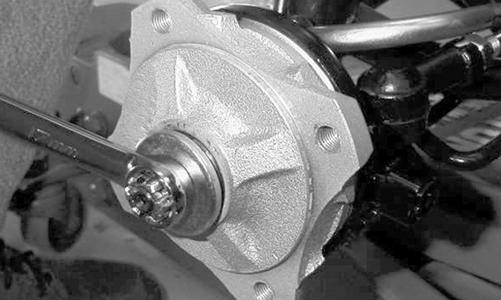
2.Remove the rear wheels; then remove the rear hub caps and hub nuts. Discard the cotter pins. 3.Remove the rear axle assembly (see Rear Drive
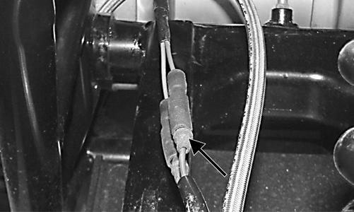
Axle); then remove the rear shock absorber. 4.Disconnect the speed sensor wire connectors; then remove the brake hose and speed sensor wires from the holder on the swing arm.
TR229A
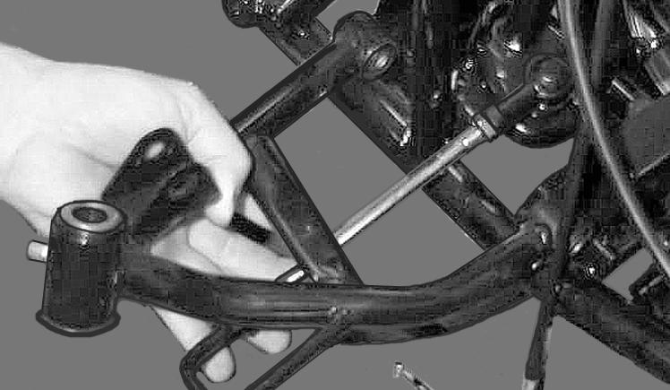
5.Remove the nut from the swing arm pivot bolt; then remove the bolt and swing arm. CLEANING AND INSPECTING NOTE: Whenever a part is worn excessively,
cracked, or damaged in any way, replacement is necessary.
1.Inspect the dust seals, bushings, and pivot axle for wear or damage. If any defect is found, they must be replaced. 2.To inspect the swing arm and swing arm axle, place the swing arm axle and bushings in the swing arm; then using the flange bolt, rock the bushings and axle from side to side and up and down. If excessive play is noted, the bushings, axle, or swing arm must be replaced. Check for cracks or broken welds. 3.Remove and clean all pivot bushings, thrust bearings, and pivot axle; then coat all parts with grease and install in the swing arm pivot. ASSEMBLING AND INSTALLING 1.Place the swing arm assembly into position in the frame making sure the swing arm thrust covers are properly positioned; then install the pivot bolt and secure with the nut. Tighten to 50 ft-lb. 2.Install the rear shock absorber and secure with the mounting cap screws and nuts. Tighten to 29 ft-lb. 3.Install the rear axle assembly (see Rear Drive Axle); then install the brake caliper and secure with the cap screws (coated with blue Loctite #242). Tighten to 24 ft-lb. 4.Insert the grommet with brake hose and speed sensor wires into the wire holder on the swing arm; then connect the speed sensor wires to the main harness. 5.Install the rear hubs and tighten the nuts to 50 ft-lb; then secure with new cotter pins. Install hub caps.
SP366
6.Install the rear wheels and tighten the nuts to 32 ft-lb; then remove the support stand and lower the ATV to the floor. 7.Check chain tension (see Drive Chain) and make sure the brake functions normally.
Front A-Arms
REMOVING 1.Secure the ATV on a support stand to elevate the front wheels; then remove the wheel on the side being serviced.
2. Remove the cotter pin, castle nut, and washer; then remove the hub assembly.
! WARNING
Make sure the ATV is solidly supported on the support stand to avoid injury.
MD2133
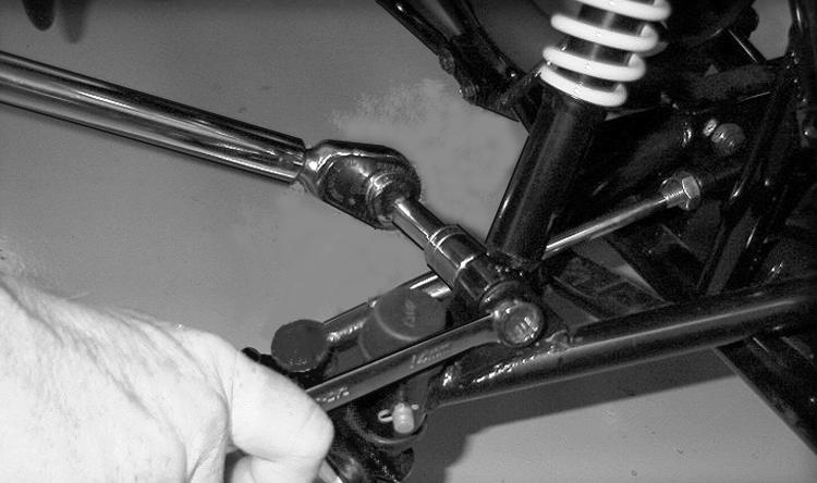
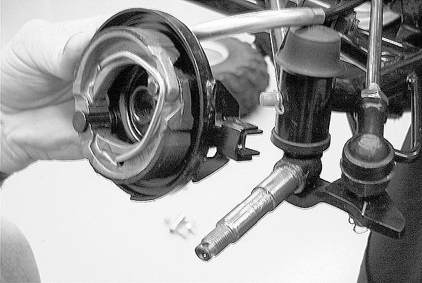
3.Slide brake backing plate assembly off the spindle shaft and secure it out of the way. 4.Remove the cotter pin from the outer tie rod end; then while holding the flat on the tie rod end, remove the castle nut.
MD2428
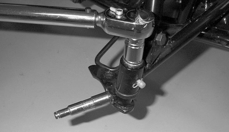
5.Remove the tie rod end from the steering knuckle. 6.Remove the rubber spindle pin boot; then remove the cotter pin and flanged castle nut from the spindle pin.
Lower the steering knuckle assembly from the Aarm.
MD2113
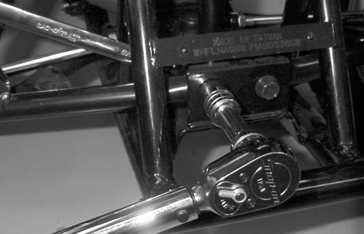
7.Remove the cap screw and self-locking nut securing the shock absorber to the A-arm.
MD2132
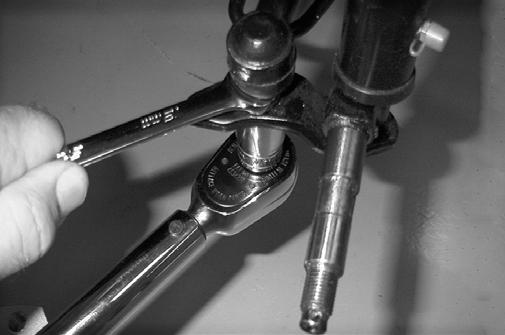
8.Remove the cap screws and self-locking nuts securing the A-arm to the frame.
MD2121
9.Remove the A-arm.
MD2119
CLEANING AND INSPECTING
NOTE: Whenever a part is worn excessively,
cracked, or damaged in any way, replacement is necessary.
1.Clean all A-arm components in parts-cleaning solvent. 2.Clean the tie rod mounting hole of all residual Loctite, grease, oil, or dirt for installing purposes. 3.Inspect the A-arm for bends, cracks, and worn bushings. 4.Inspect the tie rod mounting holes for cracks or damage. 5.Inspect the frame mounts for signs of damage or wear. INSTALLING NOTE: During installing, new cotter pins should be
installed.
1.Lubricate the A-arm bushings with grease; then install the A-arm into the frame. Install the cap screws and self-locking nuts. Tighten the nuts to 32 ft-lb.
MD2425
2.Secure the shock absorber to the A-arm with the cap screw and self-locking nut. Tighten the nut to 29 ftlb.
CAUTION
Do not tighten the nut beyond the 29 ft-lb specification or the shock eyelet or mount WILL be damaged.
MD2424
3.Lubricate the steering knuckle assembly with grease; then install it into the A-arm and secure with the flanged castle nut. Tighten the nut to 32 ft-lb; then install a new cotter pin and the rubber spindle pin boot.
MD2427
4.Install the tie rod end into the steering knuckle and secure it with the self-locking nut. Tighten the nut to 32 ft-lb; then install a new cotter pin.
MD2426
5.Apply a light coat of grease to spindle shaft; then install the brake backing plate assembly onto the shaft. NOTE: When installing the brake backing plate
assembly, be sure to align the notch in the backing plate with the tab on the steering knuckle.
MD2381
6.Place the hub assembly onto the spindle; then install the washer and castle nut. Tighten the castle nut to 50 ft-lb; then install a new cotter pin. Install the wheel and tighten the lug nuts to 32 ft-lb.
Wheels and Tires
TIRE SIZE
! WARNING
Use only Arctic Cat approved tires when replacing tires. Failure to do so could result in unstable ATV operation.
The ATV is equipped with low-pressure tubeless tires of the size and type listed (see General Specifications). Do not under any circumstances substitute tires of a different type or size. TIRE INFLATION PRESSURE Tire inflation pressure should be as specified in Gerneral Specifications. REMOVING 1.Secure the ATV on a support stand to elevate the wheels.
! WARNING
Always use the size and type of tires specified. Always maintain proper tire inflation pressure.
! WARNING
Do not mix tire tread patterns. Use the same pattern type on front and rear. Failure to heed warning could cause poor handling qualities of the ATV and could cause excessive drive train damage not covered by warranty.
! WARNING
Make sure the ATV is solidly supported on the support stand to avoid injury.
2.Remove the wheels. NOTE: Keep left-side and right-side wheels sepa-
rated for installing them on their proper sides.
CLEANING AND INSPECTING
NOTE: Whenever a part is worn excessively,
cracked, or damaged in any way, replacement is necessary.
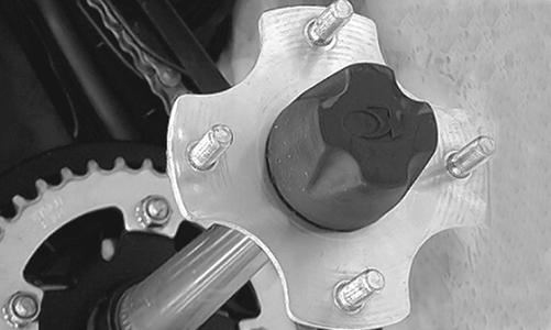
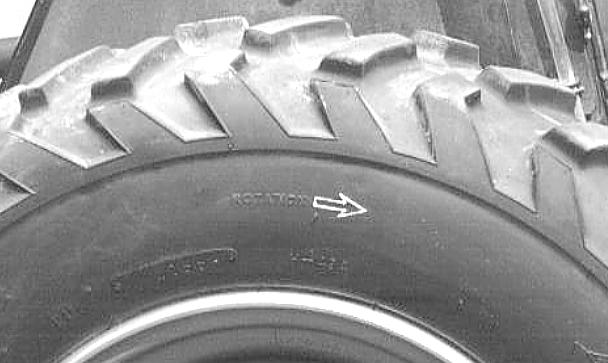
1.Clean the wheels and hubs with parts-cleaning solvent. 2.Clean the tires with soap and water. 3.Inspect each wheel for cracks, dents, or bends. 4.Inspect each tire for cuts, wear, missing lugs, and leaks. INSTALLING 1.Install each wheel on its hub. NOTE: Make sure each wheel is installed on its
proper hub as noted in removing (the “rotation arrow” must indicate forward direction of rotation).
AF612D
2.Tighten to 32 ft-lb. CHECKING/INFLATING 1.Using an air pressure gauge, measure the air pressure in each tire. Adjust the air pressure as necessary to meet the recommended inflation pressure. 2.Inspect the tires for damage, wear, or punctures. ! WARNING
Do not operate the ATV if tire damage exists.
NOTE: If repair is needed, follow the instructions
found on the tire repair kit or remove the wheel and have it repaired professionally.
NOTE: Make sure all tires are the specified size and
have identical tread pattern.
3.Check the front wheel toe-in and toe-out and adjust as necessary. 4.Test drive the ATV on a dry, level surface and note any pulling to the left or right during acceleration, deceleration, and braking.
NOTE: If pulling is noted, measure the circumfer-
ence of the front and rear tires on the pulling side. Compare the measurements with the tires on the opposite side. If pulling is noted during braking only, check and adjust the brakes as necessary and recheck operation.
5.Increase the air pressure in the tires with the smallest circumference measurement until all tires are equal in circumference. 6.Repeat steps 4-5 as necessary to ensure proper handling.
Troubleshooting
Problem: Suspension too soft Condition Remedy
1. Spring(s) weak 2. Shock absorber damaged 1.Replace spring(s) 2.Replace shock absorber
Problem: Suspension too stiff Condition Remedy
1. A-arm-related bushings worn or binding 1.Replace bushing
Problem: Suspension noisy Condition Remedy
1. Cap screws (suspension system) loose 1.Tighten cap screws 2. A-arm-related bushings worn 2.Replace bushings
Problem: Rear wheel oscillation Condition Remedy
1. Rear wheel hub bearings worn - loose 1.Replace bearings 2. Tires defective - incorrect 2.Replace tires 3. Wheel rim distorted 3.Replace rim 4. Wheel hub cap screws loose 4.Tighten cap screws 5. Axle shaft nut loose 5.Tighten nut 6. Auxiliary brake adjusted incorrectly 6.Adjust brake 7. Rear suspension arm-related bushing worn 7.Replace bushing 8. Rear shock absorber damaged 8.Replace shock absorber 9. Rear suspension arm nut loose 9.Tighten nut