7 minute read
Steering/Frame

The following steering components should be inspected periodically to ensure safe and proper operation.
A.Handlebar grips not worn, broken, or loose.
B.Handlebar not bent or cracked and has equal and complete full-left and full-right capability.
C.Steering post bearing assembly/bearing housing not broken, worn, or binding.
D.Ball joints not worn, cracked, or damaged.
E.Tie rods not bent or cracked.
F.Knuckles not worn, cracked, or damaged.
G.Cotter pins not damaged or missing. The frame, welds, and racks should be checked periodically for damage, bends, cracks, deterioration, broken components, and missing components.
Steering Post/Tie Rods
REMOVING 1.Remove the front rack and front center panel (see
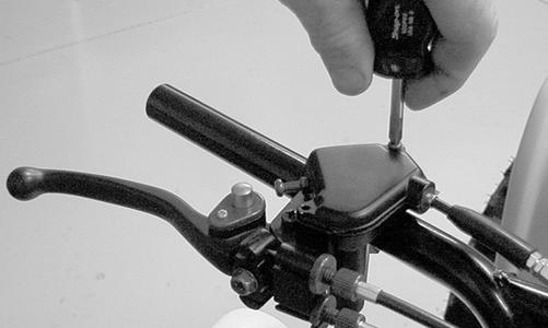
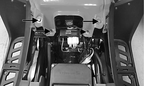
Body). 2.Remove the instrument pod; then remove the cap screws securing the handlebar to the steering post.
Account for two handlebar holders.
KM189A
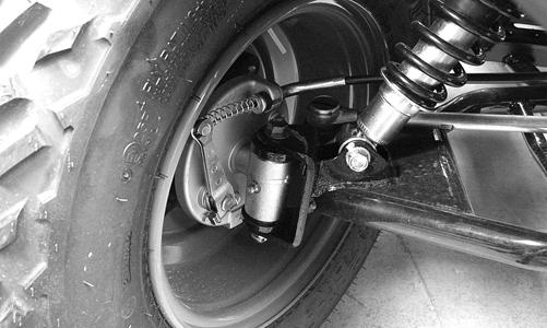
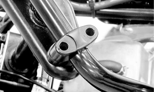
3.Lift the handlebar out of the lower handlebar holders and lay the handlebar forward. 4.Remove the cotter pins and slotted nuts securing the tie rod ends to the steering post arm; then disconnect the tie rods from the arm.
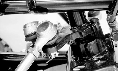
KM590
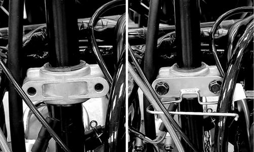
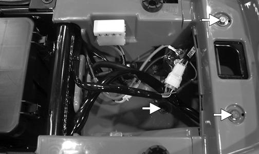
5.Remove the cotter pin and slotted nut from the lower end of the steering post; then remove the upper steering shaft support block. Account for a cable guide, two steering support blocks, and the upper steering post bushing.
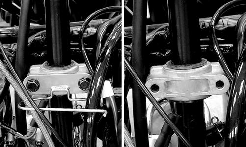
KM588
KM589
6.Remove the steering post from the ATV. CLEANING AND INSPECTING NOTE: Whenever a part is worn excessively,
cracked, or damaged in any way, replacement is necessary.
1.Wash the tie rod ends in parts-cleaning solvent. Dry with compressed air. Inspect the pivot area for wear.
Apply a low-temperature grease to the ends. ! WARNING
Always wear safety glasses when using compressed air.
3.Inspect the tie rods for cracks or unusual bends. 4.Inspect all welded areas for cracks or deterioration. 5.Inspect the steering post and steering-post holders for cracks, bends, or wear. 6.Inspect the handlebar clamps for cracks or wear. 7.Inspect the handlebar for cracks, wear, or unusual bends. 8.Inspect the handlebar grips for damage or wear. 9.Inspect the lower steering post support bearing and seal for wear or cracks. INSTALLING 1.Apply a thin coat of grease to the lips of the lower steering post seals; then lower the steering post into position in the lower steering post bearings.
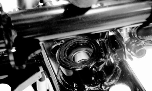
KM593
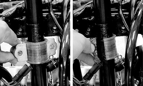
2.Apply a thin coat of grease to the upper steering post bushing; then secure the steering post with the support blocks and existing hardware. Tighten to 15 ftlb.
KM589 KM595
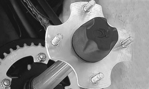
3.Install the slotted nut on the lower steering post and tighten to 50 ft-lb; then install a new cotter pin.
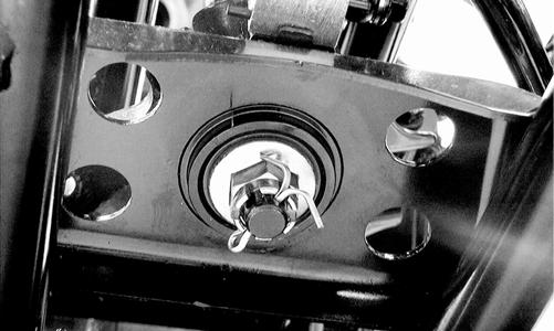
KM591
4.Place the inner tie rod ends into the steering post arm and tighten the slotted nuts to 29 ft-lb; then install new cotter pins.
KM590
5.Install the handlebar to the steering and tighten the clamp cap screws to 15 ft-lb making sure to tighten the front cap screws first.
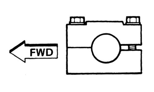
KM587
KM597
6.Install the instrument pod; then install the center panel and front rack.
Measuring/Adjusting ToeIn/Toe-Out
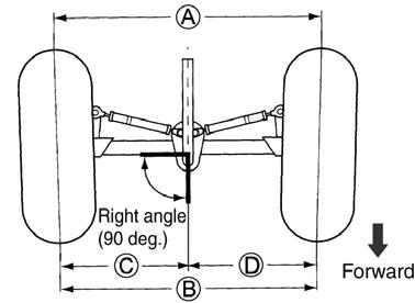
1.With the ATV on a level surface, center the handlebar for straight ahead using a suitable means of measuring centering; then adjust tire pressure to specifications. 2.Support the front of the ATV with the wheels free to rotate; then center and secure the handlebar. 3.Measure the distance (A) and (B) between the front wheels; then subtract distance (B) from (A). Distance
A - Distance B = Toe-In.
ATV2205
4.Adjust toe-in to 15 mm (0.60 in.); then measure distances (C) and (D). Distances (C) and (D) should be equal.
5.After all the adjustments are to specifications, tighten the tie-rod lock nuts to 22 ft-lb. NOTE: Prior to locking the jam nuts, make sure the
ball joints are at the center of their normal range of motion and at the correct angle.
NOTE: The front wheels do not have to be removed
to adjust the tie rod. Also, care should be taken not to disturb the handlebar position.
Body
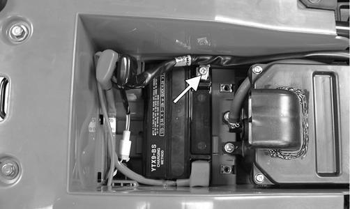
REMOVING 1.Remove the seat; then remove the battery cover.
TR007A
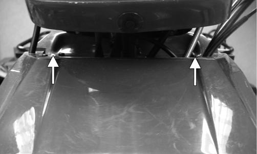
2.Disconnect the negative battery cable first; then the positive cable. Remove the battery. 3.Remove the front and rear racks; then remove the cap screws securing the front center panel and remove the panel.
KM308A
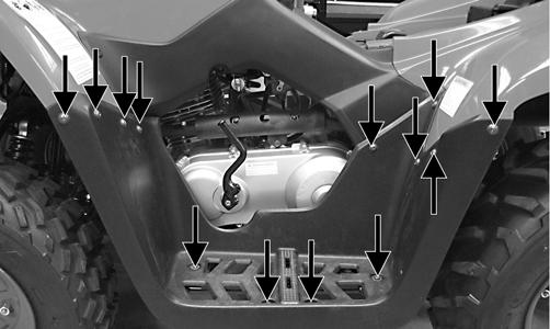
4.Remove the cap screws and flange nuts securing the mud guards to the front and rear fenders; then remove the cap screws securing the mud guards to the foot rests and remove the mud guards.
TR240A
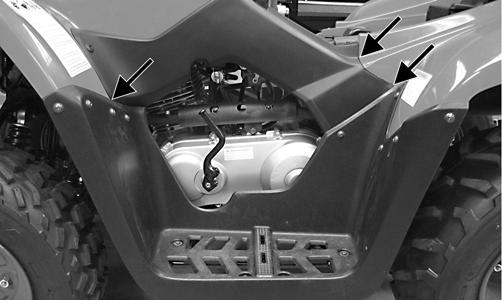
5.Remove the side panels; then remove the cap screws and flange nuts securing the front and rear fenders to the frame and fender supports.
KM799B
6.Disconnect the left and right headlight connectors; then disconnect the taillight. 7.Remove the gas tank cover; then remove the shift knob and front and rear fenders.
TR241A
CLEANING AND INSPECTING
NOTE: Whenever a part is worn excessively,
cracked, or damaged in any way, replacement is necessary.
1.Clean all body components with soap and water. 2.Inspect the body and fenders for cracks. 3.Inspect threaded areas of all mounting studs for stripping. 4.Inspect for missing decals. INSTALLING 1.Place the front and rear fenders into position on the frame and secure with the existing hardware; then install the gas tank cover. Tighten all fasteners securely. 2.Connect the headlight and taillight connectors; then install the shift knob. 3.Making sure the locating tabs engage the appropriate slots in the fenders, install the side panels.
TR240B
4.Install the mud guards and secure to the fenders and foot rest supports with the existing hardware. Make sure all locating tabs are appropriately engaged with the fenders and side panels.
TR240A
5.Install the front center cover; then install the front and rear racks. Tighten all fasteners securely. 6.Install the battery; then connect the positive battery cable, negative battery cable, and install the battery cover. NOTE: Always install the positive cable first; then
install the negative cable.
7.Install the seat making sure it locks securely in place.
Steering Post Cover/ Instrument Pod
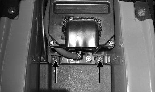
REMOVING 1.Remove the reinstallable rivet on the front of the instrument pod and the two cap screws on the rear; then lift the assembly off and disconnect the speedometer cable. 2.Remove the self-tapping screw securing the LCD gauge assembly to the instrument pod; then remove the LCD gauge.
NOTE: The LCD gauge is not a serviceable compo-
nent. If any functions are incorrect or indicator lights do not illuminate, the LCD gauge must be replaced.
INSTALLING 1.Connect the main harness connector to the LCD gauge; then connect the ignition harness to the ignition connectors. 2. Place the instrument pod onto the mounting bracket; then secure with the reinstallable rivet and two cap screws.
Troubleshooting
Problem: Handling too heavy or stiff Condition Remedy
1. Front wheel alignment incorrect 2. Lubrication inadequate 3. Tire inflation pressure incorrect 4. Tie rod ends seizing 5. Linkage connections seizing 1.Adjust alignment 2.Lubricate appropriate components 3.Adjust pressure 4.Replace tie rod ends 5.Repair - replace connections
Problem: Steering oscillation Condition Remedy
1. Tires inflated unequally 1.Adjust pressure 2. Wheel(s) wobbly 2.Replace wheel(s) 3. Wheel hub cap screw(s) loose - missing 3.Tighten - replace cap screws 4. Wheel hub bearing worn - damaged 4.Replace bearing 5. Tie rod ends worn - loose 5.Replace - tighten tie rod ends 6. Tires defective - incorrect 6.Replace tires 7. A-arm bushings damaged 7.Replace bushings 8. Bolts - nuts (frame) loose 8.Tighten bolts - nuts
Problem: Steering pulling to one side Condition Remedy
1. Tires inflated unequally 2. Front wheel alignment incorrect 3. Wheel hub bearings worn - broken 4. Frame distorted 5. Shock absorber defective
Problem: Steering impaired Condition
1.Adjust pressure 2.Adjust alignment 3.Replace bearings 4.Repair - replace frame 5.Replace shock absorber
Remedy
1. Tire pressure too high 2. Steering linkage connections worn 3. Cap screws (suspension system) loose
Problem: Tire wear rapid or uneven Condition
1.Adjust pressure 2.Replace connections 3.Tighten cap screws
Remedy
1. Wheel hub bearings worn - loose 2. Front wheel alignment incorrect
Problem: Steering noise Condition
1. Cap screws - nuts loose 2. Wheel hub bearings broken - damaged 3. Lubrication inadequate 1.Replace bearings 2.Adjust alignment
Remedy
1.Tighten cap screws - nuts 2.Replace bearings 3.Lubricate appropriate components