6 minute read
BRAKES


Two keys are provided w ith each vehicle. The keys operate the ignition switch and door locks.
EMERGENCY STARTING
• Never tow the vehicle to start because the surge forward w hen the engine starts could cause a collision w ith the tow vehicle. • Engines in vehicles w ith autom atic transmissions cannot be started by pushing the vehicle. • To start the vehicle when the Energizer (battery) is discharged, use a single auxiliary battery or Energizer of the same nominal voltage as the discharged battery, w ith suitable jum per cables. • Make connections as set fo rth below under “ Jum p
Starting With A uxiliary (Booster) B attery” to lessen the chance o f personal injury or property damage.
C A U T IO N : Never expose battery to open flame or electric spark—battery action generates hydrogen gas which is flammable and explosive. D on't allow battery fluid to contact skin, eyes, fabrics, or painted surfaces—fluid is a sulfuric acid solution which could cause serious personal injury or property damage. Wear eye protection when w orking with battery.
Jump Starting With Auxiliary (Booster) Battery
Both booster and discharged battery should be treated carefully when using jum per cables. Following exactly the procedure outlined below, being careful n o t to cause sparks:
1. Set parking brake and place autom atic transmission in
L-6 MODELS
V -8 MODELS
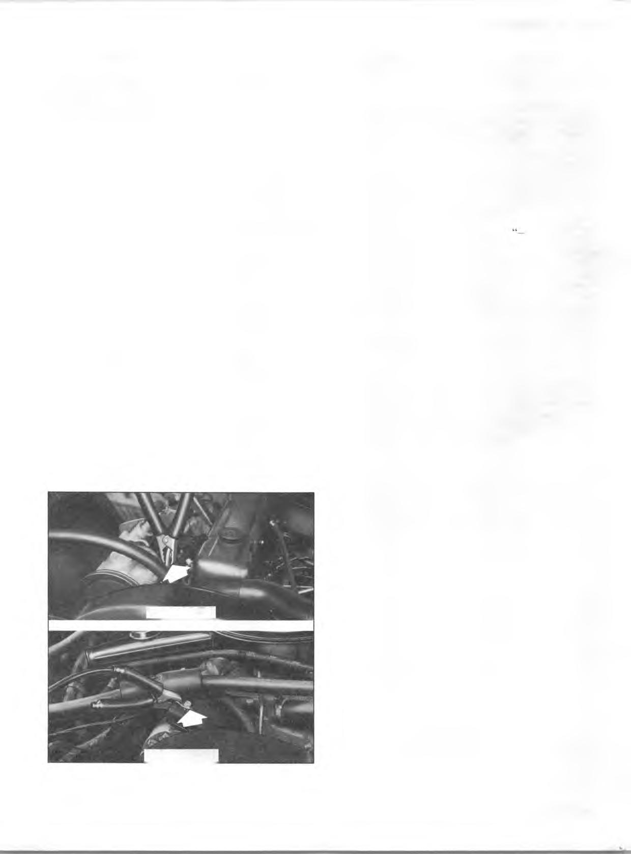
Fig. 4—Booster Battery Cable Ground Connection.
“ PARK” (neutral for manual transm ission). T urn off lights, heater and other electrical loads. 2. Remove vent caps from b o th the booster and the discharged batteries. Lay a cloth over the open vent wells o f each battery. These two actions help reduce the explosion hazard always present in either battery when connecting “live” booster batteries to “ dead” batteries. 3. A ttach one end of one jum per cable to the positive term inal o f the booster battery (identified by a red color,
“ +” or “ P ” on the battery case, post or clamp) and the other end o f same cable to positive term inal o f discharged battery. Do NOT perm it vehicles to touch each other, as this could establish a ground connection and counteract the benefits o f this procedure. 4. A ttach one end o f the remaining negative ( —) cable to the negative term inal (black color, ” or “ N ”) o f the booster battery, and the other end to the engine lift bracket on 6 cylinder models and the delcotron m o un ting bracket on V8 models (see Figure 4) o f your 1972 vehicle (do not connect directly to negative post o f dead b attery)—taking care th a t clamps from one cable do not inadvertently touch the clamps on the other cable. Do n ot lean over the b attery when making this connection.
Reverse this sequence exactly when removing the jum per cables. Re-install vent caps and throw cloths away as the cloths may have corrosive acid on them .
C A U T IO N : Any procedure other than the above could result in: (1) personal injury caused by electrolyte squirting out the battery vents, (2) personal injury or property damage due to battery explosion, (3) damage to the charging system of the booster vehicle or of the immobilized vehicle.
Do not attem pt to jump start a vehicle having a frozen battery because the battery may rupture or explode. If a frozen battery is suspected, examine all fill vents on the battery. If ice can be seen, or if the electrolyte fluid cannot be seen, do not attempt to start with jumper cables as long as the battery remains frozen.
PUSH STARTING
If your vehicle is equipped w ith a m anual transmission, it can be started in an emergency by pushing. When being pushed to start the engine, tu rn o ff all unnecessary electrical loads, turn ignition to “ ON,” depress the clutch pedal and place the shift lever in high gear. Release the clutch pedal when speed reaches 10 to 15 miles per hour. Bumpers and other parts contacted by the pushing vehicle should be protected from damage during pushing. Never tow the vehicle to start.
TOWING
Normally your vehicle m ay be tow ed w ith all four wheels on the ground for distances up to 50 miles at speeds o f less than 35 MPH. The engine should be off and the transmission in neutral.
However, the rear wheels m ust be raised off the ground or
the drive shaft disconnected w hen the transm ission is not operating properly or when a speed o f 35 MPH or distance of 50 miles will be exceeded.
C A U T IO N : If a truck is towed on its front wheels only, the steering wheel must be secured with the wheels in a straight ahead position.
Vehicle Displacement Cyl. Comp. Ratio Spark Plugs
GS 10-20-30 250 Cu. In. L6 8.5:1 R 4 6 - T
GE 10 307 Cu. In. V 8 8.0:1 R 4 4 - T
GE 20-30 350 Cu. In. V 8 9.0:1 R 4 4 - T
LOAD CAPACITY CHART INTERPRETATIO N
The first colum n of the Load Capacity Chart shows the basic model series.
The n ex t column reflects the wheelbases available within each series.
The th ird colum n shows the Gross Vehicle Weight (GVW) ratings applicable to each series vehicle. GVW means the m axim um design weight o f the vehicle itself and all equipm ent added to the vehicle after it has left the factory, the driver weight and occupant weight and everything th at is loaded into or onto the vehicle.
F o llo w in g th e GVW c o lu m n s are the m inim um recom m ended tires to qualify the vehicle for each GVW rating.
The tire pressures listed in the colum n adjacent to the tire sizes in the chart are the m inim um required tire pressures for m aximum permissible loads.
The letters “ B.E.” under the F ront and Rear Axle and Spring columns indicate th at base equipm ent is satisfactory to qualify the vehicle for any given GVW rating. When the letters “ RPO” denoting Regular Production O ption, followed by a num ber appears in these columns (exam ple RPO G 50), the vehicle m ust be equipped w ith the extra cost equipm ent specified by the RPO to qualify the vehicle for the given GVW rating.
The ratings shown under the colum ns identified “M aximum F ront E nd Weight at G round” and “ M aximum Rear End Weight at G round” indicates the m axim um permissible loading or weight at the ground regardless o f spring or axle capacity ratings. These ratings are developed on the basis o f the m inim um com ponent capability be it axles, springs or tires.
In loading the vehicle, the com bined front and rear end weights at the ground m ust not exceed the GVW specified for the vehicle as m anufactured.
In trailer hauling applications, the vehicle rear end weight at the ground w ith trailer attached m ust n o t exceed the “M aximum Rear End Weight at G round” rating of the vehicle.
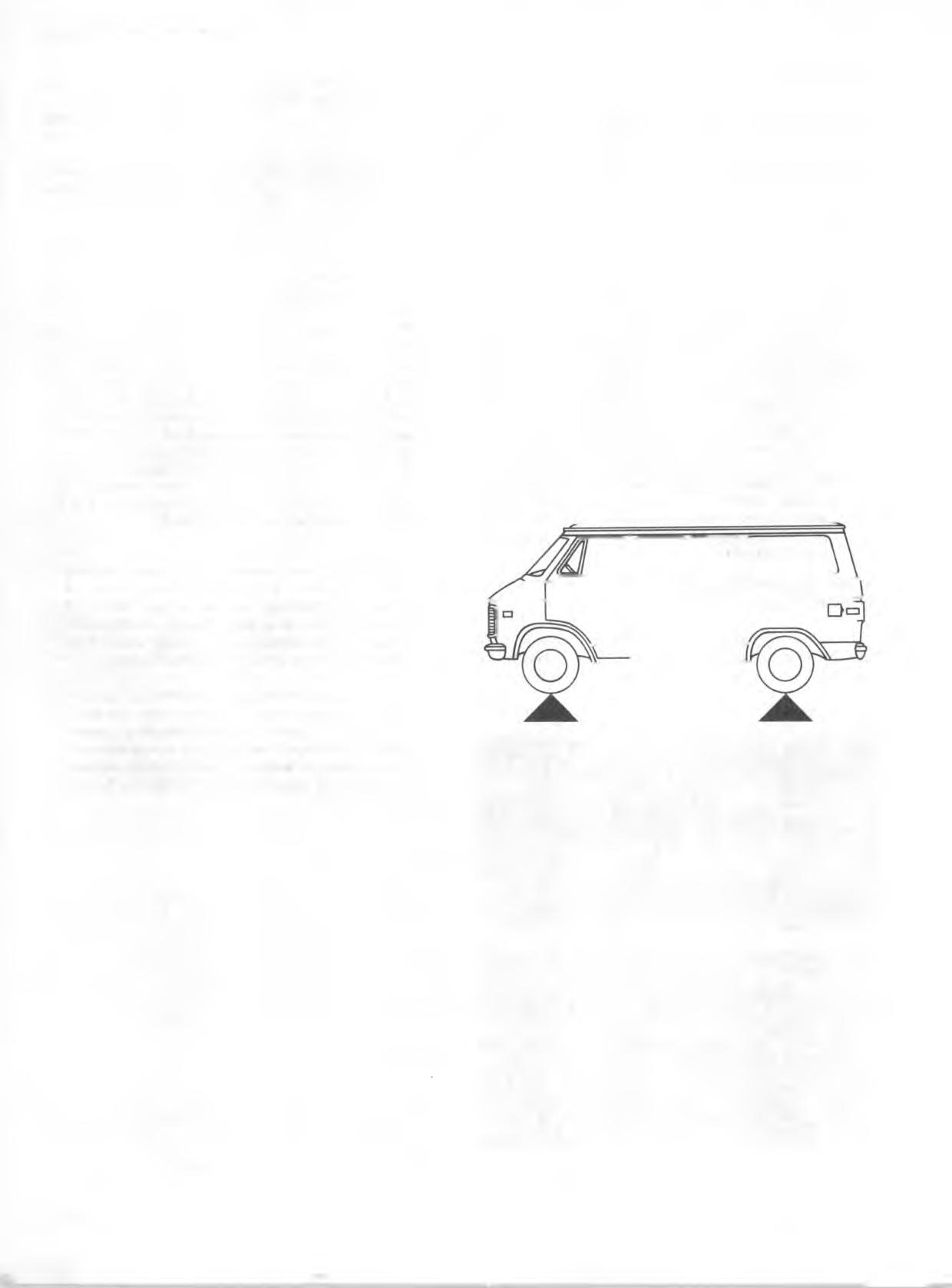
A typical example of a T ruck in a loaded condition is shown in Figure 5. N ote th a t the axle or GVW capabilities are n ot exceeded.

LO A D E D -M A X IM U M G VW : 4 5 0 0 LBS.
FR O N T A X LE CAPACITY: 2500 LBS. REAR A X LE CAPACITY: 2300 LBS.
Front Curb 1959 lbs. Rear Curb 1562 lbs. Front Cargo Rear Cargo
Load 300 lbs. Load 650 lbs. 2259 lbs. 2212 lbs.
TOTAL WEIGHT AT GROUND: 4471 lbs.
Fig. 5—Typical Vehicle Loaded Condition