26 minute read
Forw ard Control Chassis


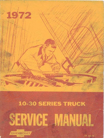
CAPILLARY BULB
EXTERNAL EQUALIZER LINE
OUTLET
Fig. 33—Expansion Valve
POORLY LOCATED POWER ELEMENT BULB
Normal P re ssu re .
Poor Cooling.
Check for Defective Valve
The following procedure must be followed to determ ine if a malfunction is due to a defective expansion valve. 1. Check to determ ine if the system will meet the p e rform ance te st as outlined previously. If the expansion valve is defective, the low p ressu re readings (POA o r evaporator p ressu re) will be above specification. 2. The loss of system perform ance is not as evident when the com pressor head p re ssu re is below 200 PSI.
T herefore, it may be necessary to increase the system head p re ssu re by partially blocking the condense r. Disconnect the blower lead wire and repeat the
“ Peform ance Check'’ to determ ine if the evaporator p re ssu re can be obtained. 3. The system will also indicate a low refrig eran t charge by bubbles occurring in the sight glass. Systems equipped with a POA Valve require the following additional te st to determ ine if the deficiency is the expansion valve. 4. Remove the expansion valve bulb from the evaporator outlet pipe, and the connector on the blower re sisto r.
Place the blower on "low." With the engine operating at 2,000 rpm , observe the POA gauge p ressu re. 5. Insert the expansion valve bulb in a cup of ice. This should resu lt in the POA p re ssu re being reduced to approxim ately 30 P.S.I. If the p re ssu re does not reduce to this level, the POA valve is defective. If the p ressu re falls considerably below 30 P.S.I., the expansion valve is defective.
ENGINE IDLE COMPENSATOR
This additional aid to prevent stalling during prolonged hot weather periods is included with all a ir conditioned vehicles. The idle com pensator is a therm ostatically controlled a ir bleed which supplies additional a ir to the idle m ixture. On V-8 engines, with factory installed a ir conditioning system s, the com pensator is located within the carburetor and is accessible when the engine a ir cleaner is removed. On all other vehicles the compensator is threaded into a manifold fitting below the c a rburetor. All com pensators are factory set and are non- adjustable. A malfunctioning unit should be replaced. NOTE: If engine idle is e rra tic , hold the idle com pensator valve closed with a pencil or wooden dowel while adjusting the idle mixture screw (s). Never attem pt to bend the bimetal strip or attem pt any valve adjustm ent.
COMPONENT PART REPLACEMENT
ALL SYSTEMS
COMPRESSOR
Rem oval (Fig. 34) 1. Purge the refrig eran t from the system . 2. Remove connector attaching bolt and connector. Seal connector outlets. 3. Disconnect electrical lead to clutch actuating coil. 4. Loosen brace and pivot bolts and detach belt. 5. Remove the nuts and bolts attaching the com pressor brackets to the mounting bracket. 6. Before beginning any com pressor disassem bly, drain and m easure oil in the com pressor. Check for evidence of contamination to determ ine if rem ainder of system req u ires servicing. C om pressor se rv ic ing inform ation is located in the C hassis Overhaul
Manual.
Installation 1. If oil previously drained from the com pressor upon removal shows no evidence of contamination, replace a like amount of fresh refrig eratio n oil into the com p re sso r before reinstallation. If it was necessary to service the entire system because of excessive contamination in the oil rem oved, install a full charge of fresh refrigeration oil in the com pressor. 2. Position com pressor on the mounting bracket and install all nuts, bolts and lock w ashers. 3. Install the connector assem bly to the com pressor re a r head, using new "O" rings coated with clean refrigeration oil. 4. Connect the electrical lead to the coil and install and adjust com pressor belt. 5. Evacuate, charge and check the system .

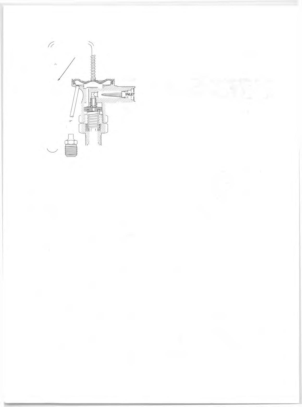
Fig. 34—Compressor Mountings
Compressor Belt Tension Adjustment
Adjust the com pressor belt to the specifications shown in the Tune-Up chart in the Engine Specification section of this manual.
CONDENSER (Fig. 35)
Replacem ent 1. Disconnect battery ground cable. 2. Purge the system of refrig eran t. 3. Remove the hood catch assem bly. 4. Remove the radiator and shroud upper brackets. 5. Disconnect the condenser inlet and outlet lines and cap or tape the open connections at once. 6. Remove the radiator shroud screw s and move the radiator rearw ard fa r enough to gain access to the condenser mounting screw s. 7. Remove the four condenser retaining screw s and carefully lift the condenser up out of the vehicle. 8. To install a new condenser, re v erse steps 1-7 above.
Add one fluid ounce of clean refrigeration oil when installing a new condenser.
NOTE: Use new “ O” rings coated with clean refrigeration oil when connecting all refrig eran t lines. 9. Evacuate, charge and check system operation.
RECEIVER-DEHYDRATOR
The receiver-dehydrator should be replaced if it has been damaged through an accident or if it leaks or becomes re stric te d or clogged. Do not attem pt to rep air the receiver-dehydrator.
The receiver-d ehydrator is m erely a m oisture collecting device and a refrig eran t storage a re a and is the least likely component of the system to cause a malfunction.
If at any tim e when examining the com pressor oil, m oisture is found or there is an indication of m oisture at the expansion valve needle, the receiver-d eh ydrator should be replaced as follows (fig. 35).
C AU TIO N : If the receiver-dehydrator is to be reused, cap the inlet and outlet connections imm ediately. When installing a receiv er- dehydrator, do not uncap the connections until the last possible moment.
Rem oval 1. Disconnect battery ground cable. 2. Purge the system . 3. Remove the inlet and outlet connections from the receiver-dehydrator.
R O O F M O U N T E D SYSTEM
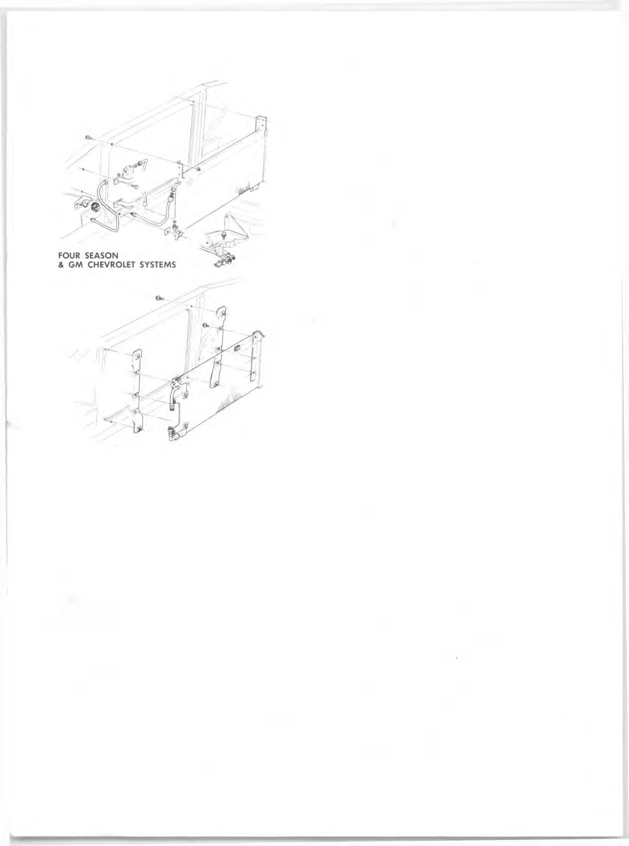
Fig. 35—Condenser and Receiver-Dehydrator
4. Remove the receiver-dehydrator mounting bolts and carefully remove it. 5. Cap the system if the receiver-dehydrator will not be replaced im m ediately. Cap the receiv er if it will be reused.
Installation 1. Place the receiv er-dehydrato r in position and r e place attaching bolts. Do not uncap the unit until im m ediately before connecting lines. 2. Uncap any previously capped connections and connect the fittings using new "O" ring seals, coated with clean refrigeration oil. 3. Evacuate, charge and check the system . If a new receiver-dehydrator was installed, add one fluid ounce refrigeration oil to the system .
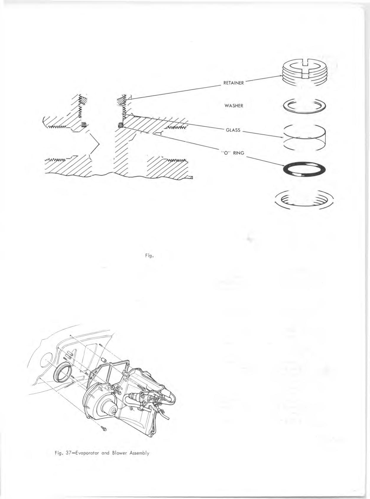
SIGHT GLASS REPLACEMENT
If damage to the sight glass should occur, a new sight g lass kit should be installed. The kit contains the sight glass, seal and retainer. (See Figure 36). 1. Purge system . 2. Remove the sight glass retain er nut using a screw driver and remove old glass and "O" ring seal. 3. Install the new glass and seal and retain er nut, being careful not to turn the nut past the face of the housing.
To do so may damage the "O" ring seal. 4. Evacuate, charge and check the system .
FOUR-SEASON SYSTEM
BLOWER ASSEMBLY
Rem oval 1. Disconnect battery ground cable. 2. Support the right front of the hood in the fully raised position. 3. Carefully scribe the hood and fender locations of the right hood hinge and remove the hinge. 4. Unclip the blower wire at the blower flange term inal and note or m ark the m otor flange position in relation to the blower case. Disconnect the rubber cooling tube to the motor. 5. Remove the blower assem bly mounting screw s. 6. Remove the blower assem bly (pry the flange away from the case carefully if the sealer acts as an adhesive). 7. Remove the nut attaching the blower wheel to the motor shaft and separate the assem bly.
Installation 1. Assemble the blower wheel to the motor with the open end of the blower away from the motor. 2. Install the assem bly to the blower case, connect ground strap, and connect the m otor w ire. Connect cooling tube to motor. 3. Remount the hood hinge aligning it carefully with the scribed lines. Check hood alignment. 4. Connect battery ground cable.
EVAPORATOR CORE
Rem oval 1. Disconnect battery ground cable and purge the system . 2. Disconnect the evaporator core inlet line at the expansion valve. Cap the open connections. 3. Disconnect the evaporator oil bleed line at the POA valve. Cap the open connections. 4. Disconnect the evaporator outlet pipe at the POA valve. Cap the open connections. Remove the evaporato r outlet pipe clamp. 5. Detach the expansion valve capillary bulb from the evaporator outlet pipe. 6. Disconnect the vacuum lines at the vacuum re se rv o ir. 7. Remove the screw s attaching the inboard case half to the outboard case half, back up plate, and dash. 8. Remove inboard case half and evaporator core.
Installation 1. Assem ble evaporator core and inboard case half to the outboard case half. Replace case to case, case to back up plate, and case to dash panel mounting screw s. 2. Attach the vacuum lines to the vacuum reserv o ir. 3. Mount the expansion valve capillary bulb to the evaporator core outlet pipe. 4. Connect the evaporator outlet pipe to the POA valve

36—Sight Glass Replacement
using a new "O" ring, coated with clean refrigeration oil. Install the pipe clamp. 5. Connect the evaporator oil bleed line to the POA valve. 6. Connect the line from the evaporator core to the expansion valve using a new "O" ring, coated with clean refrigeratio n oil. 7. If a new evaporator was installed, add three fluid ounces of refrigeration oil to the system . Connect battery ground cable. Evacuate, charge and check the system .
BLOWER AND EVAPORATOR CASE
Rem oval (Fig. 37)
1. Purge the refrig eratio n system and drain the radiator. 2. Disconnect battery ground cable. 3. Unclip the blower m otor wire at the blower flange term inal. 4. Disconnect h eater hoses at the core tubes. 5. Disconnect the refrig eran t lines at the POA valve outlet and the expansion valve inlet. Cap all open connections. 6. Remove vacuum hoses to vacuum re se rv o ir and plenum air valve actuator. 7. Disconnect tem perature door cable. 8. In order to gain access to the lower outboard case attachm ents, the right front fender sk irt should be loosened and moved. Remove enough sk irt mounting screw s and bolts (from the re a r forward) to move the sk irt a sufficient amount. 9. Remove the case retaining screw s and sheet m etal nuts. Pull the case away from the mounting studs and inboard to remove it.
Installation 1. Check the position of the blower and evaporator case to dash panel seals then position the case over the studs projecting through the dash panel and attach the screw s and nuts to retain the case. Connect the blower m otor ground strap. Replace spacer between case and dash panel at the screw next to the tem perature door lever. 2. Remount the right front fender skirt. 3. Connect tem perature door cable and vacuum hoses (hose to engine vacuum source attaches to vacuum tank connection n earest the engine). 4. Connect the re frig eran t hoses to the expansion valve inlet and the POA outlet using new "O" ring seals, coated with clean refrig eratio n oil. 5. Connect the heater hoses to the core tubes (fig. 38). 6. Connect the blower m otor wire to the m otor flange term inal, and connect the battery ground cable. 7. Refill the cooling system , and evacuate, charge and check the refrig eratio n system . HEATER CASE
Rem oval (Fig. 39) 1. Drain the radiator. Disconnect battery ground strap. 2. Remove the heater hoses from the core tubes. 3. Remove the sheet m etal nuts from the heater case studs which project through the dash to the engine side. 4. Remove the glove box. 5. Unplug the relay connector. 6. Remove the right ball outlet hose. 7. Remove the screw attaching the dash outlets a ir distributor to the h eater case and move distributor away from case. 8. Remove the heater case to dash panel retaining screw s. 9. Pull the heater case away from the dash panel and reach in and disconnect the re sisto r connector. 10. Remove the re sisto r harness grom m et and remove the harn ess from the case. Withdraw the heater case.


Installation 1. Place the heater case under the dash and in sert the re sisto r harness and install the grom m et and connect the re sisto r connector. 2. Position the heater case against the dash panel and push it into place. Check that nothing is pinched between the case and dash panel. Install the heater case to dash retaining screw s. 3. Position the dash outlets distributor against the heater case, in sert the forw ard lip into the retaining clip, and install the retaining screw . 4. Install the right dash outlet hose. 5. Connect the relay connector. 6. Install the glove box. 7. Install the sheet m etal nuts to the heater case studs which project forw ard through the dash panel. 8. Attach the heater hoses to the core tubes and connect battery ground strap. 9. Refill the engine cooling system and test system operation.
HEATER CORE
Rem oval 1. Remove the heater case as outlined under Heater
Case. 2. Remove the screw s retaining the core mounting strap s. 3. Remove core.
Installation 1. Install the core into the case and seal it with nonhardening sealer. 2. Mount the core with the core strap s and retaining screw s. 3. Replace the heater case in the vehicle as outlined under H eater Case.
WATER VALVE (Fig. 38)
Rem oval 1. Place a container under the vehicle and then disconnect the shut-off valve inlet and outlet lines. Drain coolant into container. 2. Disconnect the valve vacuum line and remove the valve.
Installation 1. Install the coolant lines onto the new valve, making sure that coolant flows through the valve in the right direction. 2. Install the vacuum line onto the valve. 3. Refill the radiator.
EXPANSION VALVE
Rem oval 1. Disconnect battery ground cable and purge the system . 2. Loosen the clamp retaining the high p re ssu re line to the bracket next to the expansion valve. 3. Disconnect the capillary bulb from the evaporator outlet pipe. Disconnect the equalizer line from the
POA. Cap the POA connector. 4. Disconnect the expansion valve inlet and outlet connections and cap the lines. 5. Remove expansion valve to bracket mounting screw and remove expansion valve.
Installation 1. Mount the expansion valve to the bracket. 2. Connect the inlet and outlet connections. Tighten the inlet pipe clamp„ 3. Connect the equalizer line to the POA using new "O" ring coated with clean refrigeration oil and mount the capillary bulb to the evaporator outlet pipe. 4. Connect battery ground cable. Evacuate, charge and check the system .
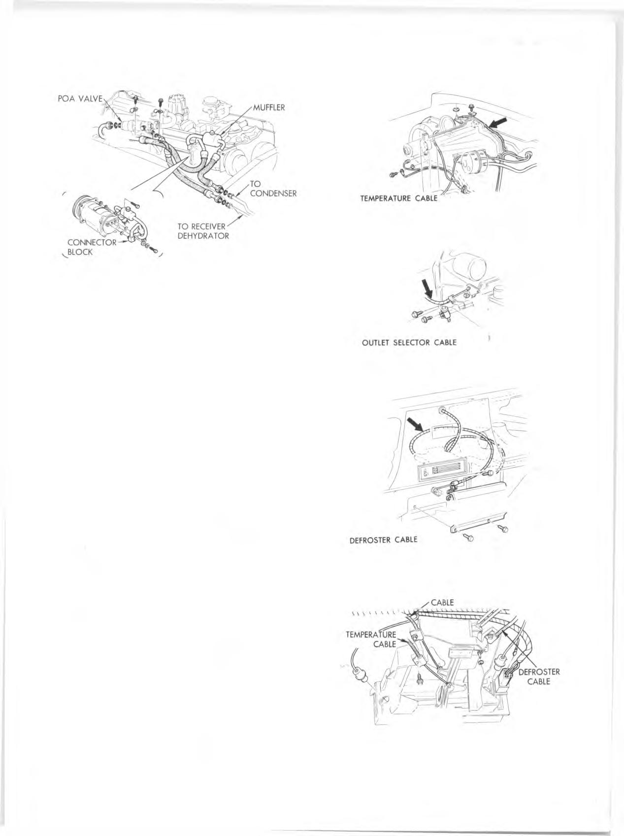
MUFFLER, CONNECTOR BLOCK & HOSE ASSEMBLY (Fig. 41)
The com pressor inlet and outlet hoses are swaged to the connector block and m uffler assem bly. If the a ssembly is not repairable (See “ Hose Repair” ), proceed as follows:
Replacem ent 1. Purge the system . 2. Disconnect the outlet hose at the condenser inlet pipe and the com pressor inlet hose at the POA valve. Cap
WATER VALVE (TYPICAL)
VIEW 307-350 V-8 WITH MAN U AL TRANS. 400 V-8 WITH MAN U AL TRANS.

307-350 V-8 WITH AUTO TRANS. 400 V-8 WITH AUTO TRANS.
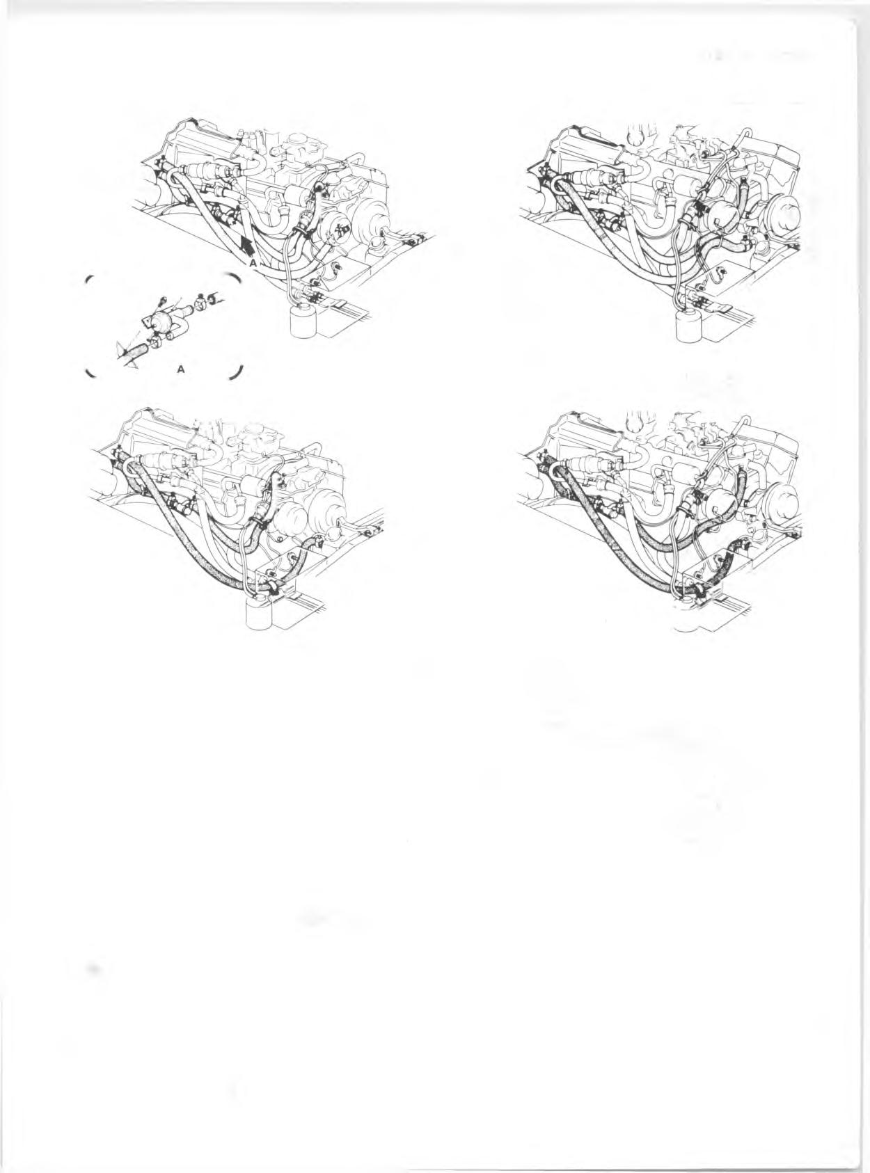
Fig. 38—A/C and Heater Hose Routing-Typical
or tape the open connections at once. D iscard the "O" ring seals. 3. Remove the connector block to com pressor bolt and rem ove the m uffler, hoses and connector block. Cap or tape the open connections. D iscard the "O" ring seals. 4. Assem ble the new connector block to the com pressor using new "O" ring seals coated with clean re frig e ra tion oil. Tighten the connector block bolt to 25 ft. lbs. 5. Attach the com pressor inlet and outlet hoses at the
POA valve and condenser inlet pipes using new "O" ring sea ls coated with clean refrigeration oil. 6. Evacuate, charge and check system operation. 4. Remove POA valve inlet and outlet connections and remove POA valve. Cap the open tubes. 5. Remove clamp from POA valve.
Installation 1. Assem ble clamp on POA valve and connect inlet and outlet connections using new "O" ring seals coated with clean refrig eration oil. 2. Secure POA valve clamp and outlet line clamp. 3. Connect the evaporator oil bleed line and the expansion valve equalizing line to the POA valve using new ”0 " ring seals coated with clean refrigeration oil. 4. Connect battery ground cable. Evacuate, charge and check the system .
POA VALVE
Rem oval 1. Disconnect battery ground cable and purge the system . 2. Remove evaporator oil bleed line and expansion valve equalizer line. Cap the connections. 3. Remove retaining clamp screw and loosen POA valve outlet pipe clamp mounting screw . CONTROL ASSEMBLY
Rem oval (Fig. 42) 1. Disconnect battery ground cable. 2. Remove the screw s in the lower lip of the dash which attach the control assem bly bracket to the dash. 3. Move the unit toward the front of the vehicle and low er it.
Fig. 39—Heater and Ducts
4. Disconnect the blower h arness connector and illum inating lamp sockets. Remove the blower switch and mounting bracket. Remove the vacuum control switch. 5. Remove the control cables and tran sfer them to the replacem ent control unit. Check them for adjustment.
Installation 1. Attach the blower switch to the unit. Connect the harness connector and illuminating lam ps. Attach the mounting bracket. Install the vacuum switch and hoses. 2. Lift the unit into position and attach it to the dash. 3. Connect the battery ground cable.
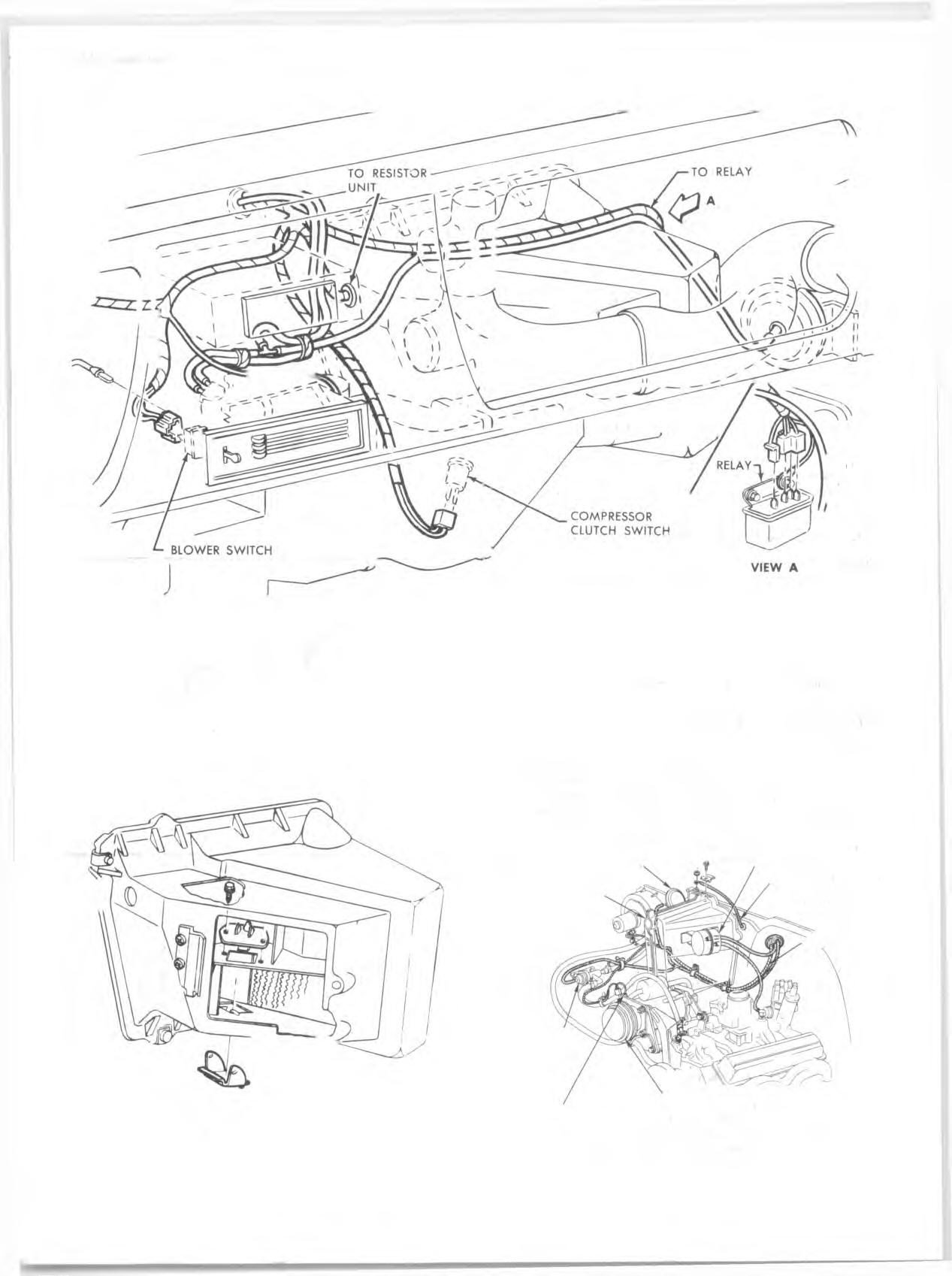
BLOWER MOTOR SWITCH (Fig. 43)
Rem oval 1. Disconnect battery ground cable. 2. Disconnect wiring harness connector at blower switch. 3. Remove blower switch mounting screw s and remove switch.
Installation 1. Place blower switch in position and install mounting screw s. 2. Connect wiring harn ess to switch. 3. Connect battery ground cable.
BLOWER MOTOR RELAY (Fig. 43)
Rem oval 1. Disconnect wiring harness at relay connector. 2. Remove the relay mounting screw s and remove relay.

Fig. 40—A ir Outlets and Hoses
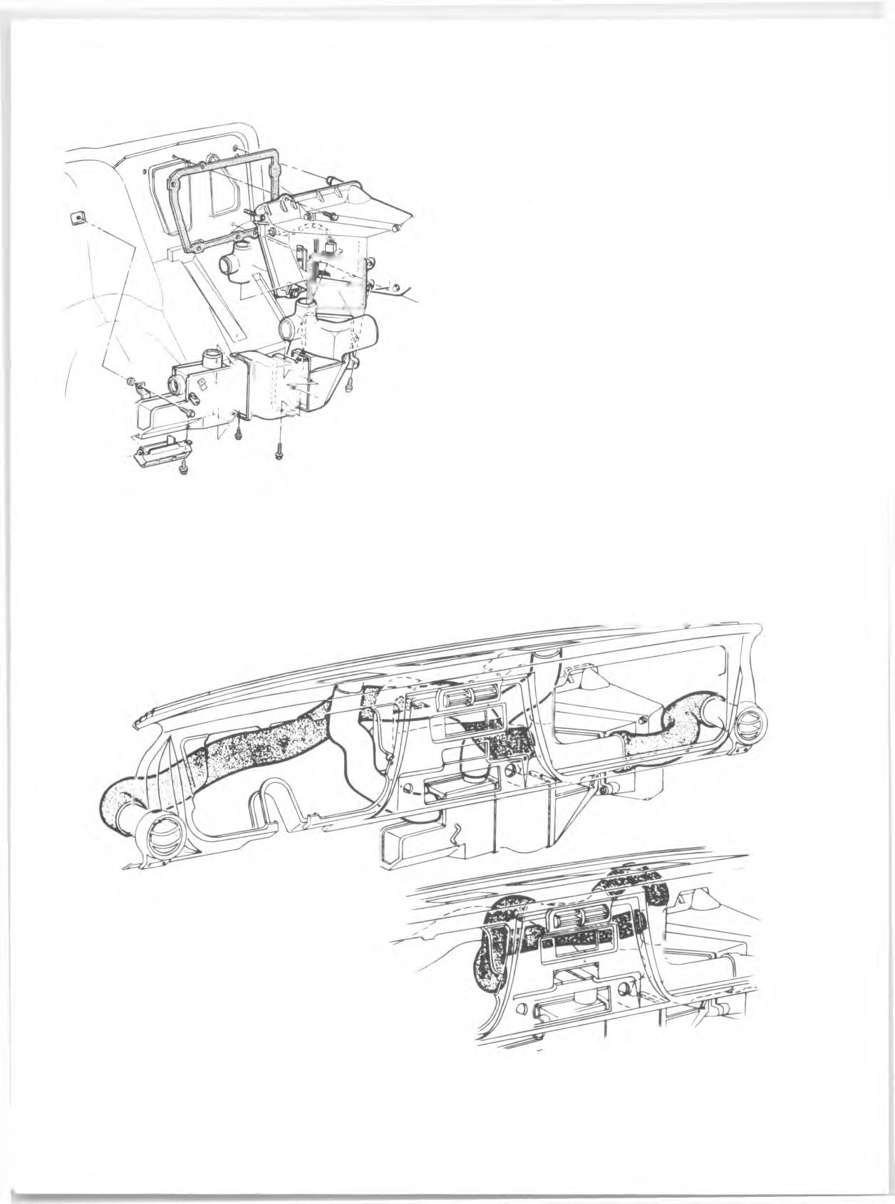
Fig. 41—Muffler, Connector Block and Hose Assy. (Typical)
Installation 1. Place relay in position and drive mounting screw s. 2. Connect wiring harness to relay.
COMPRESSOR CLUTCH SWITCH (Fig. 43)
Rem oval 1. Disconnect wiring harn ess at com pressor clutch switch. 2. Remove two mounting screw s and remove switch.
Installation 1. Place switch in position and drive the two mounting screw s. 2. Connect wiring harness to switch.
BLOWER RESISTOR UNIT
Rem oval (Fig. 44) 1. Remove the screw attaching the floor outlet duct (above the heater outlet) to the dash panel. 2. Remove the screw s attaching the distributor to the h eater case, slide the distributor downward out of re a r slide and let it re s t on the floor panel. 3. Unplug the re sisto r unit connector. 4. Remove the re sisto r unit retaining screw s. Remove the unit.
Installation 1. Place the replacem ent unit in position and install mounting screw s. 2. Connect the re sisto r connector. 3. Position the dash outlet a ir distributor against the h eater case, in se rt the forw ard lip into the retaining clip, and install the retaining screw s. 4. Mount the floor outlet duct to the dash panel with the attaching screw .
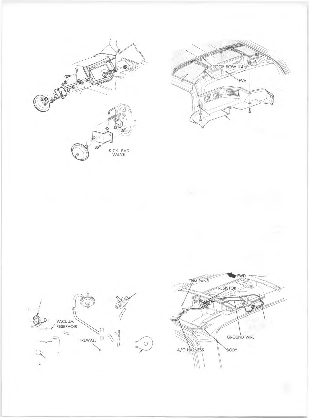
KICK PANEL AIR VALVE
Rem oval (Fig. 45) 1. Disconnect vacuum hose from actuator. 2. Disconnect valve retu rn spring. 3. Remove actuator bracket mounting screw s.
OUTLET SELECTOR
Fig. 42—A ir Conditioning Controls
Fig. 43—Wiring and Vacuum Harness-Underdash

4. Remove link retain er at actuator and lift link up out of actuator. Remove actuator assem bly. 5. Remove actuator from bracket.
Installation 1. Attach actuator to bracket. 2. Install link in actuator and install retain er on link. 3. Mount the bracket to the kick panel. 4. Connect the valve retu rn spring. Connect the vacuum hose to the actuator.
PLENUM AIR VALVE
Rem oval (Fig. 46) 1. Remove cowl grille panel. R efer to Section 11. 2. Disconnect the diaphragm link from the connecting shaft arm .
VACUUM ACTUATOR (AIR INLET VALVE) EVAPORATOR AND BLOWER VACUUM TANK
TEMPERATURE
CABLE
HARNESS
Fig. 44—Resistor Unit WATER SHUT-OFF VALVE
GROUND WIRE COMPRESSOR
Fig. 45—Electrical and Vacuum Harness-Engine Compartment
PLENUM VALVE
P. & BLO W ER A SM
Fig. 46—A ir Inlet Valve and Recirculating Air Valve

3. Remove the screw attaching the connecting shaft to the tube extending forw ard from the valve. 4. Remove the screw s attaching the nylon bearing plate to the dash panel and slide it forw ard. 5. Pull the re a r valve pivot pin forw ard against spring tension until it clears the re a r bearing. Lift the valve at the re a r and withdraw the valve shaft from the dash panel.
Installation 1. In sert the tube shaft on the valve into the dash panel hole and lower the valve into position with the re a r pivot pin retracted. When the re a r pin is aligned with its bearing, allow it to extend into position. 2. Attach valve retu rn spring and nylon bushing.
W A T ER VALVE- (CLO SED WITH V A C U U M APPLIED) OUTSIDE AIR RECIRCULATED AIR DOOR DIAPHRAGM DOOR DIAPHRAGM (DOOR CLOSED WITH (DOOR OPEN WITH VACUUM APPLIED) VACUUM APPLIED)
VACUUM SOURCE CONTROL HEAD VACUUM SWITCH
Fig. 47—Vacuum Diagram SHROUD A SM
Fig. 48—Blower-Evaporator Duct Installation
3. Assem ble the connecting shaft to the valve and actuating diaphragm. 4. Replace the cowl grille panel.
I
ROOF M O U N TED SYSTEM
The Roof-Mounted System is used in conjunction with the Four-Season System. Since replacem ent of Four- Season System components has been covered previously, only those components peculiar to the Roof-Mounted System will be covered in this section.
REAR DUCT (Fig. 48)
This duct covers the blow er-evaporator assem bly, at the re a r of the vehicle, and incorporates four adjustable a ir outlets.
Replacement 1. Disconnect the battery ground cable. 2. Disconnect the drain tubes from the re a r duct.
ROOF
BLO W ER-EVAPO RATO R ASSEMBLY
WIRING HARNESS
Fig. 49—Blower-Evaporator Installation
3. Remove the four screw s securing the duct to the roof panel. 4. Remove the duct from the side and re a r retaining flanges and remove the duct. 5. To install, re v erse Steps 1-4 above.
BLOWER MOTOR RESISTOR
The blower m otor re s is to r is located on the right side of the blow er-evaporator as shown in Figure 49.
Replacem ent 1. Disconnect battery ground cable. 2. Remove the re a r duct as described previously. 3. Disconnect the ele ctrical harness at the re sisto r. 4. Remove the re sisto r attaching screw s and remove the re sisto r. 5. To install a new re sisto r, rev erse Steps 1-4 above.
BLOWER MOTOR ASSEMBLY
Rem oval 1. Disconnect the battery ground cable. 2. Remove the re a r duct as outlined previously. 3. Disconnect the blower m otor ground strap. 4. Disconnect the blower m otor lead wire. 5. Remove the lower to upper blow er-evaporator case screw s and lower the lower case and motor assem bly.

C A U T IO N : Before removing the case screw s, support the lower case to prevent damage to the case or m otor assem blies. 6. Remove the motor retaining strap and remove the m otor and wheels. Remove the wheels from the m otor shaft.
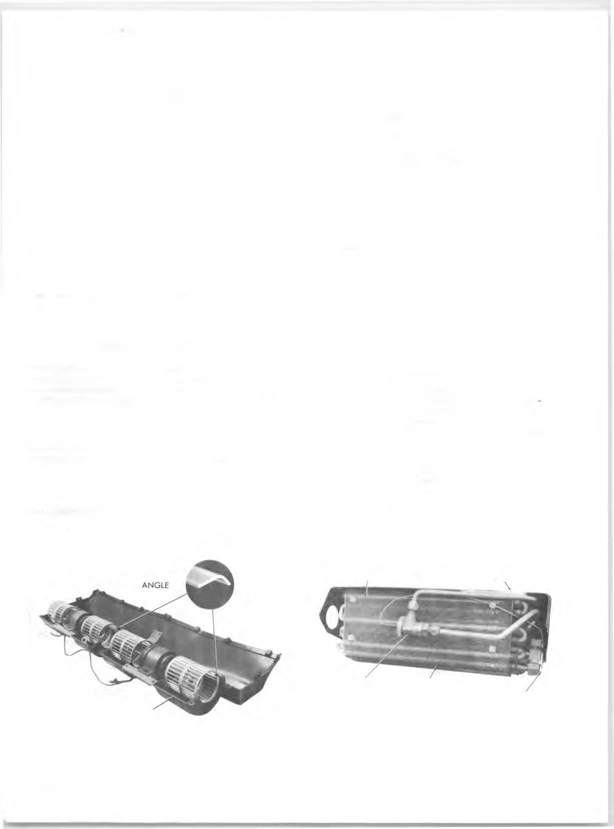
Installation 1. Place the blower wheels onto the m otor shaft and install the set screw s; do not tighten the set screw s at this tim e.
C A U TIO N : Be sure that the blower wheels are installed as shown in Figure 50. 2. Install the blower m otor retaining strap and foam. 3. Place the blower m otor and wheel assem bly into the lower case. Align the blower wheels so that they do not contact the case and then tighten the wheel set screw s. 4. Place the lower case and blower m otor assem bly in position in the vehicle and in stall the lower to upper case screw s.
CORRECT BLADE
NOTE: Rotate the blower wheels to make sure that they do not rub on the case. 5. Install the center ground w ire and connect the blower lead wire. 6. Install the re a r duct assem bly as described previously. 7. Connect the battery ground cable.
EXPANSION VALVE
This system incorporates an expansion valve which does not utilize an external equalizer line (fig. 51).
Rem oval 1. Disconnect the battery ground cable. 2. Purge the system of refrigerant. 3. Remove the re a r duct as outlined previously. 4. Disconnect the blower m otor lead and ground w ires. 5. Remove the lower to upper blow er-evaporator case screw s and lower the lower case and motor assem bly.
C AU TIO N : Before removing the case screw s, support the lower case and m otor assem blies. 6. Remove the expansion valve sensing bulb clamps. 7. Disconnect the valve inlet and outlet lines and re move the expansion valve assem bly. Cap or tape the open connections at once.
Installation 1. Remove caps or tape from system connections and install the new valve assem bly using new "O " rings coated with clean refrigeration oil. 2. Install the sensing bulb, making sure that the bulb makes good contact with the core outlet line.
EVAPORATOR SCREEN BLOWER-EVAPORATOR UPPER CASE
LOWER CASE HALF
Fig. 50—Blower Motor Installation-Typical EXPASION EVAPORATOR
VALVE CORE SENSING BULB
Fig. 51—Evaporator and Expansion V a lv e
3. Install the lower case and blower m otor assem blies.
Connect the blower m otor lead and ground w ires. 4. Install the re a r duct as outlined previously. 5. Connect the battery ground cable. 6. Evacuate, charge and check the system .
EVAPORATOR CORE (Fig. 51)
Rem oval 1. Disconnect the battery ground cable. 2. Purge the system of refrigerant. 3. Remove the re a r duct as outlined previously. 4. Disconnect the blower m otor lead, ground w ire, and re sisto r connections. 5. Disconnect the refrig eran t lines at the re a r of the blow er-evaporator assem bly. 6. Remove the blow er-evaporator to roof panel support nuts and w ashers, lower the blow er-evaporator a ssembly and place it on a work bench upside down. 7. Remove the lower to upper case screw s and remove the lower case assem bly. Remove the upper case from the evaporator core. 8. Remove the expansion valve inlet and outlet lines and cap or tape the open connections at once. Remove the expansion valve capillary bulb from the evaporator outlet line and remove the valve. 9. Remove the plastic pins holding the screen to the core and remove the screen.
Installation 1. Install the wire screen to the front of the core and in se rt the plastic pins. 2. Install the expansion valve inlet and outlet lines using new "O ” rings coated with clean refrigeration oil. Install the sensing bulb to the evaporator outlet line as shown in Figure 51, make sure the bulbs have good contact with the line. NOTE: Add 3 oz. clean refrigeration oil when installing a new core. 3. Install the upper case to the core. 4. Install the lower core case and blower assem bly. 5. Install the blow er-evaporator to the roof panel support. 6. Connect the refrig eran t lines to the blower- evaporator unit using new “ 0 ” rings coated with clean refrigeration oil. 7. Connect the blower lead w ires, ground strap, and re sisto r harn esses. 8. Install the re a r duct as outlined previously. 9. Connect the battery ground cable. 10. Evacuate, charge and check the system .

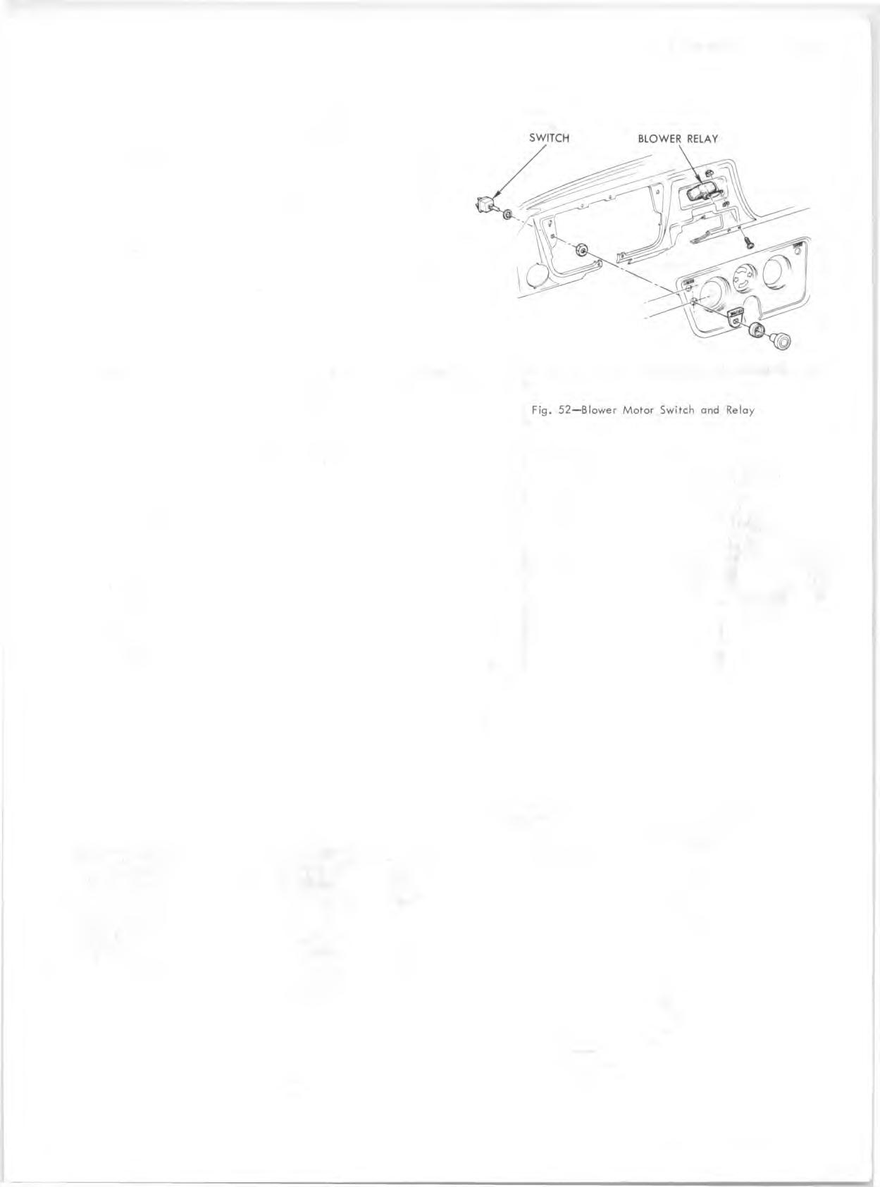
BLOWER RELAY (Fig. 52)
The blower relay is attached to the instrum ent panel reinforcem ent, just left of the cigarette lighter.
Replacem ent 1. Disconnect battery ground cable. 2. Disconnect the relay wiring harness at the relay. 3. Remove the relay attaching bolt and remove the relay. 4. To install, rev erse Steps 1-3 above. BLOWER MOTOR SWITCH
The three-speed (LO-MED-HI) blower m otor switch is located in the instrum ent panel, just below the light switch (fig. 52).
Replacem ent 1. Disconnect the battery ground cable. 2. Remove the switch knob, bezel and plate. 3. Remove the switch retaining nut and lockwasher. 4. Disconnect the wiring harness at the switch and remove the switch. 5. To install, rev erse Steps 1-4 above.
FUSE
The Four Season portion of this system is protected by a 25 amp fuse in the junction block.
The re a r blower high speed circuit is protected by a 25 amp in-line fuse, located between the junction block and the re a r blower relay.
G M CHEVROLET SYSTEM
COMPRESSOR, CONDENSER, RECEIVERDEHYDRATOR AND SIGHT GLASS
Replacement of these components is covered under "A L L SYSTEMS” .
BLOWER RESISTOR
Replacem ent 1. Disconnect the battery ground cable. 2. Remove the glove box and door assem blies. 3. Disconnect the re s is to r wiring harness. 4. Remove the two re s is to r mounting screw s and remove the re sisto r as shown in Figure 54. 5. To install, rev e rse "Removal" Steps 1-4.
SIDE MEMBER HOSE
UNDERBODY
INLET HOSE
ENGINE COMPARTMENT
BLOWER - EVAPORATOR A SSEM BLY \\\\
HOSE - DRAIN HOSE
DRAIN HOSE,
OUTLET HOSE TO BLOWER
REAR PILLAR
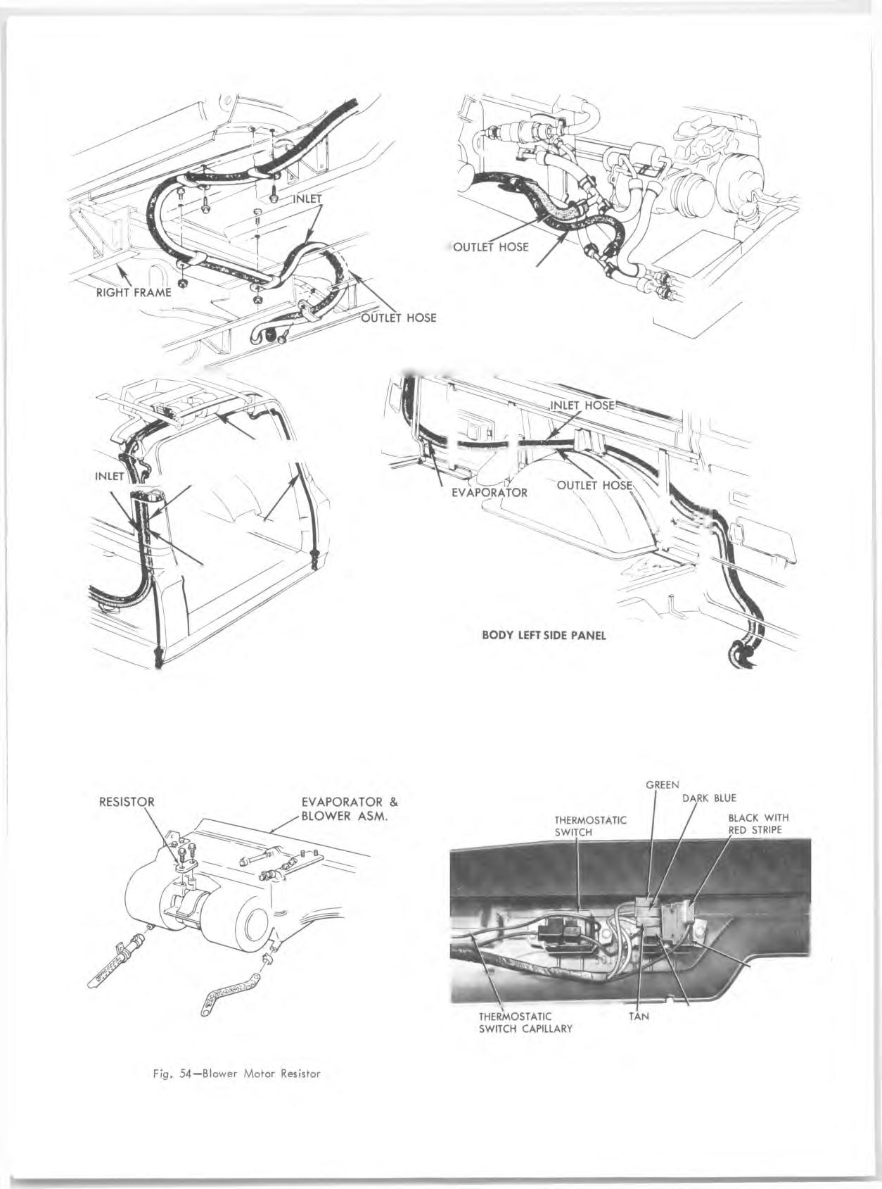
Fig. 53—A/C Hose Routings
BLACK BLOWER SWITCH
Fig. 55—Thermostatic and Blower Sw itch Locations