26 minute read
Throttle Bell Crank - L-6 6,000 Miles Engine Oil As required


INSTALL VALVE WITH ARROW POINTING A W A Y FROM TEE.
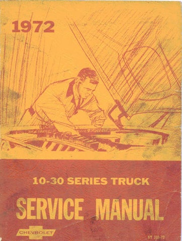
Fig. 11—Auxiliary Heater Control Switch
Fig. 10—Auxiliary Heater Water Valve
COMPONENT REPLACEMENT AND REPAIRS
Since a detailed list of installation instructions is included with the auxiliary heater unit, replacem ent procedures will not be repeated in this section.
C AU TIO N : All Models—When replacing heater hoses, m aintain a 1-1/8" minimum clearance between the auxiliary h eater core outlet line and the exhaust pipe (fig. 12). Draw hoses tight to prevent sag or rub against other components.
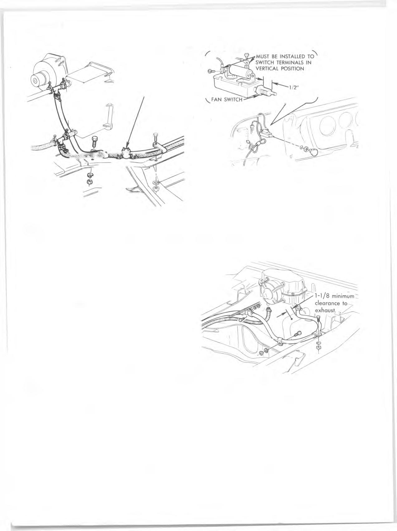
Fig. 12—Auxiliary Heater Hose Routing-Suburban Models
A I R C O N D I T I O N I N G
IN DEX
Page

General Description....................................................................................... 1A-7
Four-Season System ............................................................................. 1A-7
Roof-Mounted System ............................................................................. 1A-9
GM Chevrolet System ............................................................................. 1A-10 General Information .................................................................................. 1A-12
Precautions in Handling Refrigerant-12 ............................................1A-12
Precautions in Handling Refrigerant Lines .......................................1A-12
Maintaining Chemical Stability in the Refrigeration System . . . 1A-13
J-8393 Charging Station .........................................................................1A-13
Gauge Set .................................................................................................1A-14
Vacuum Pum p...........................................................................................1A-14
Leak Testing the S y stem .........................................................................1A-15
Availability of Refrigerant-12...............................................................1A-15
Compressor Oil ....................................................................................... 1A-16
Compressor Serial Number ....................................................................1A-16 Inspection and Periodic Service ...............................................................1A-16
Pre-Delivery Inspection .........................................................................1A-16 6000 Mile Inspection ............................................................................. 1A-16
Periodic Service ....................................................................................... 1A-16 Evacuating and Charging Procedures .....................................................1A-16
Air Conditioning System Capacity ..................................................... 1A-16
Installing Charging Station to Check System Operation ...............1A-16
Purging the System . . .............................................................................. 1A-17
Evacuating and Charging the System ................................................ 1A-17
Performance T est....................................................................................... 1A-19
Performance Data .................................................................................. 1A-20
Refrigerant Quick-Check Procedure..................................................... 1A-21
Checking Oil ............................................................................................1A-21 General Repair Procedures .........................................................................1A-22
Preparing System for Replacement of Component P arts...............1A-22
Foreign Material in the System .......................................................... 1A-22
Refrigerant Line C onnections...............................................................1A-22
Repair of Refrigerant Leaks....................................................................1A-22
Refrigerant Hose F ailure.........................................................................1A-23
Compressor F ailure.................................................................................. 1A-23
Collision Procedure - All Systems ..................................................... 1A-23 Maintenance and Adjustments....................................................................
Evaporator Control Valve (PO A ).......................................................... 1A-24
Thermostatic Switch ..............................................................................1A-24
Expansion V a lv e ....................................................................................... 1A-25 Page
Engine Idle Compensator..........................................................................1A-26 Component Part Replacem ent.....................................................................1A-26 All S ystem s..................................................................................................1A-26 Compressor.............................................................................................1A-27 Condenser ......................................................................................... ....1A-27 Receiver-Dehydrator ............................................................ • • • • 1A-27 Sight Glass Replacem ent....................................................................1A-28 Four-Season System ...................................................................................1A-28 Blower Assem bly...................................................................................1A-28 Evaporator Core ...................................................................................1A-28 Blower and Evaporator Case ....................................................... ...1A-29 Heater C a se......................................................................................... ...1A-30 Heater C ore......................................................................................... ...1A-30 Water V alve............................................................................................1A-30 Expansion V a lv e ...................................................................................1A-30 Muffler, Connector Block and Hose Assembly..............................1A-30 POA Valve ......................................................................................... ...1A-31 Control Assembly ..............................................................................1A-31 Blower Motor Switch .........................................................................1A-32 Blower Motor Relay .........................................................................1A-32 Compressor Clutch Switch ...............................................................1A-33 Blower Resistor Unit .........................................................................1A-33 Kick Panel Air Valve .........................................................................1A-33 Plenum Air Valve...................................................................................1A-34 Roof-Mounted System ..............................................................................1A-35 Rear Duct ......................................................................................... ...1A-35 Blower Motor Resistor.........................................................................1A-36 Blower Motor Assembly ....................................................................1A-36 Expansion V a lv e ...................................................................................1A-36 Evaporator Core ...................................................................................1A-37 Blower Relay .................................................................................... ...1A-37 Blower Motor Switch .........................................................................1A-37 Fuse...........................................................................................................1A-37 GM Chevrolet System................................................................................1A-37 Compressor, Condenser, Receiver-Dehydrator and/or Sight Glass 1A-37 Blower Resistor ..................................................................................1A-37 Blower and/or Thermostatic Sw itches............................................1A-39 Evaporator Core, Expansion Valve, Blower Motor and Wheels 1A-39 Wiring Diagrams ............................................................................................1A-41 Special Tools .................................................................................................1A-44
GENERAL DESCRIPTION
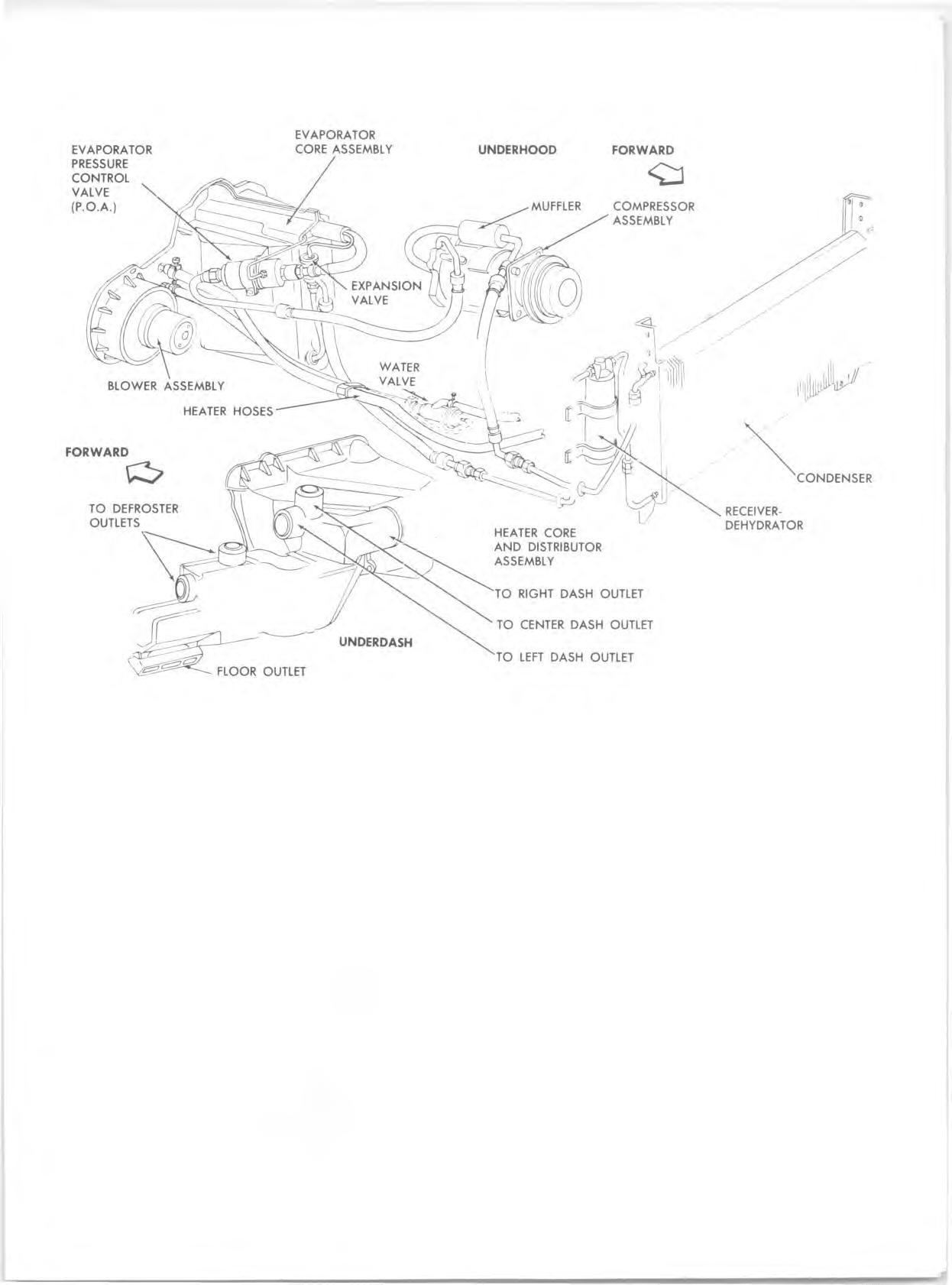
FO UR-SEASON SYSTEM
The Four-Season system uses an evaporator p re ssu re control known as the POA (P ressu re Operated Absolute) valve. The six-cylinder reciprocating com pressor is bracket-m ounted to the engine and belt driven from the crankshaft pulley. The condenser is mounted ahead of the engine cooling radiato r and the receiver-dehydrator is mounted in the refrig eran t line downstream of the conden ser. All cooling system components are connected by means of flexible refrig eran t lines.
Both the heating and cooling functions are perform ed by this system . Air entering the vehicle must pass eith er through the cooling unit (evaporator) or through the heating unit, or through both. The system is thus re fe rre d to as a p arallel system .
Fig. 13—Four Season System Controls
EVAPORATOR
OUTLET
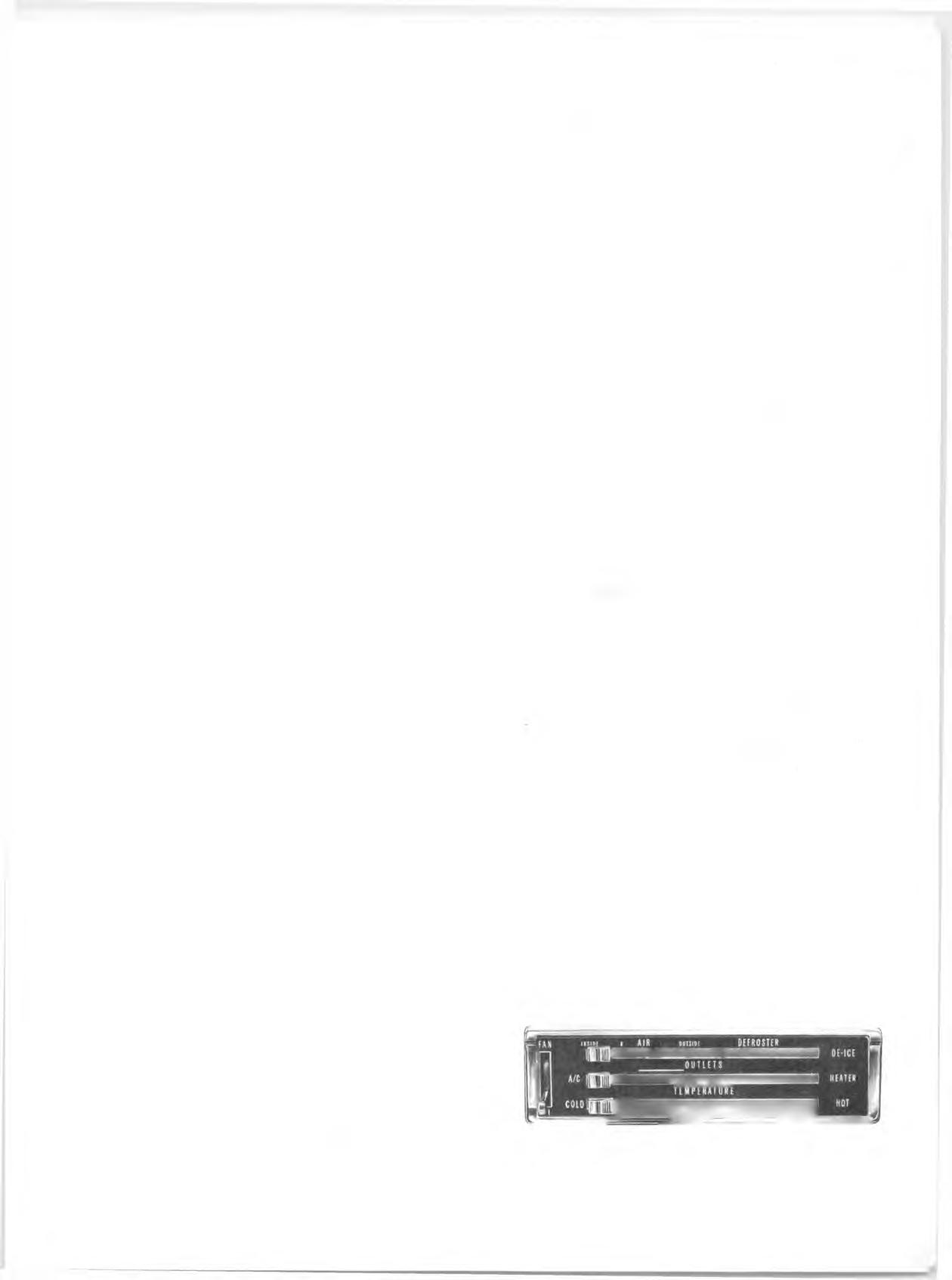
Fig. 14—Airflow Schematic

The evaporator provides maximum cooling of the air passing through the core when the a ir conditioning system is calling for cooling. The control valve acts in the system only to control the evaporator p re ssu re so that minimum possible tem perature is achieved without core freeze-u p. The valve is p re set, has no manual control, is autom atically altitude compensated, and non-repairable.
System operation is as follows (See Figure 14): Air, eith er outside a ir or recirculated a ir enters the system and is forced through the system by the blower.
The a ir passes by the tem perature door and is directed through the heating o r cooling cores, or split to flow through both. After flowing through the core or cores, the a ir p asses the outlets door which d irects it to the dash or floor outlets or both. Air directed to the dash outlets is finally controlled by the position of the air outlets. Air directed to the floor outlets p asses the d efro ste r door which directs the air out the floor outlets, the d e fro ster outlets, or both.
Linkage is so designed that when the system controls a re calling for heat, air will enter the vehicle through the floor d istributor duct, and when the system controls call for cooling, a ir will enter through the three dash outlets. The side dash outlets may be rotated to provide either soft, diffused airflow or spot cooling. Rotate half way to shut off airflow. The b a rre l type outlet in the center of the dash will d irect air up o r down o r, if desired, shut it off.
CONTROLS
Full control of the Four-Season System is obtained through the use of a single control panel (fig. 13). The control lev ers make use of bowden cables to activate the various doors and switches necessary for system operation. Control adjustm ent is a m atter of properly setting these bowden cables. The following paragraphs explain each control. “ Outlet” Lever
This lever actuates an air diverter door within the duct assem bly which routes airflow when fully right (HEATER) to the floor distributor ducts (for heater operation) or when fully left (A/C) to the dash outlets (for cooling operation).
Moving this lever toward the left from the HEATER position will activate the com pressor clutch switch and set the cooling portion of the system in operation pro viding the FAN switch is turned on.
When the lever is moved fully toward the right (heating position) the AIR control lever will autom atically move to the outside air position. Temperature Lever
The "TEMPERATURE" lever, through its bowden cable, actuates the door which controls outlet tem perature. This door is necessary to perm it mixing of hot and cool a ir to provide the desired conditioned a ir outlet tem peratu re, whether during heating or cooling operations.
The tem perature door d irects the airflow through either the heater core, the evaporator core or through both. When the system is set for full cooling, all a ir p asses through the evaporator core. When w arm er outlet a ir is desired, the tem perature door is moved by the tem perature lever so that some air p asses through the h eater core. The warmed a ir m ixes with the cooled air resulting in a higher outlet a ir tem perature. In the full HOT position, all a ir flows through the heater core. For

Fig. 15—Four Season System Components
cooler a ir, moving the lever toward COOL will send som e air through the evaporator core (inoperative when the OUTLETS lever is set for heater operation) which in effect bypasses the heater core resulting in less heat output. Air Control Lever
When the control is properly adjusted, full left position ("INSIDE") will supply 100% recircu lated inside air, and moving the lever to the word "OUTSIDE" will supply 100% outside air to the system . Lever movement contro ls a vacuum switch which in turn actuates an a ir inlet door in the plenum below the a ir inlet grille and a re c irculating a ir door in the kick pad. In the full left position, vacuum also closes the Hot W ater Shut Off Valve, p re venting coolant flow through the heater core. Defroster
As the Air control knob is moved to the right from the "OUTSIDE" position toward the word DEFROSTER the d iv e rte r door within the distributor duct moves to send a portion of the airflow to the defroster ducts. Full "right" position of the AIR knob, as indicated on the panel, is the DE-ICE position which sends the total airflow to the d e fro ste r ducts. Fan Switch
The fan switch controls the operation of the three speed blower m otor.
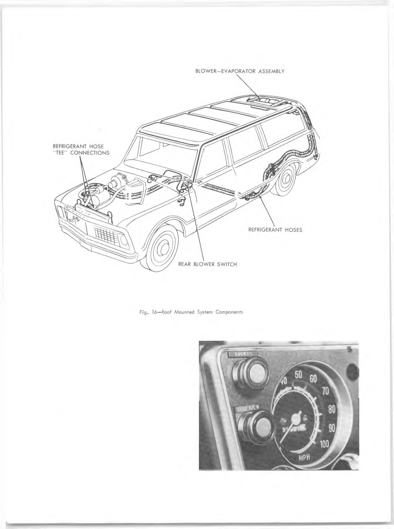
ROOF M O UNTED SYSTEM
The Roof-Mounted System is available for CKE 10-20 se rie s Suburban and Panel Trucks.
This system operates in conjunction with the Four- Season System — it is not available as a separate sy stem . This system operates on recirculated a ir only.
The blow er-evaporator assem bly is mounted to the roof panel at the re a r of the vehicle. A sm all shroud covers the unit and houses adjustable outlets. Blower m otor operation is controlled by an I.P. mounted three- speed fan switch. R efrigerant is controlled by the Four- Season system . R efrigerant control is provided for the re a r unit by an expansion valve. Refrigerant lines “ tee” into the Four-Season lines and are routed from the engine com partm ent to the evaporator as shown in Figure 16.
CONTROLS
The Four-Season controls operate as previously described. The re a r unit is controlled by a single three-

speed fan switch located on the dash, beneath the light switch. In the OFF position, the blower is totally inoperative; however, refrig eran t is circulating if the Four-Season System in ON. In any of the three positions (LO, MED, HI) the re a r blower m otor is operative; providing the Four-Season System is ON. NOTE: To obtain maximum cooling, the Four-
Season System should be on inside with the blower switch on HI and the re a r unit blower switch should be on HI.
G M CHEVROLET SYSTEM
The GM Chevrolet System is available as a dealer - in stalled accessory for C10-30 and K10-20 se rie s trucks.
This system is sim ilar to the Four-Season System in placem ent of the com pressor, condenser and receiv er- dehydrator (fig. 18). It differs from the Four-Season System in that it: 1. O perates independently of the heater system . 2. O perates on recirculated (inside) a ir only. 3. U tilizes a therm ostatic switch instead of an evaporato r control (POA) valve to control outlet a ir tem perature.
Fig. 17—Roof Mounted System Control
BLO W ER-EV A PO R A T O R A SSEM BLY
RECEIVERD EHYDRATO R FITTING & MUFFLER
C O M P R E SS O R
C O N D E N S E R

BLOWER TEMPERATURE SWITCH KNOB Fig. 18—G M Chevrolet System Components
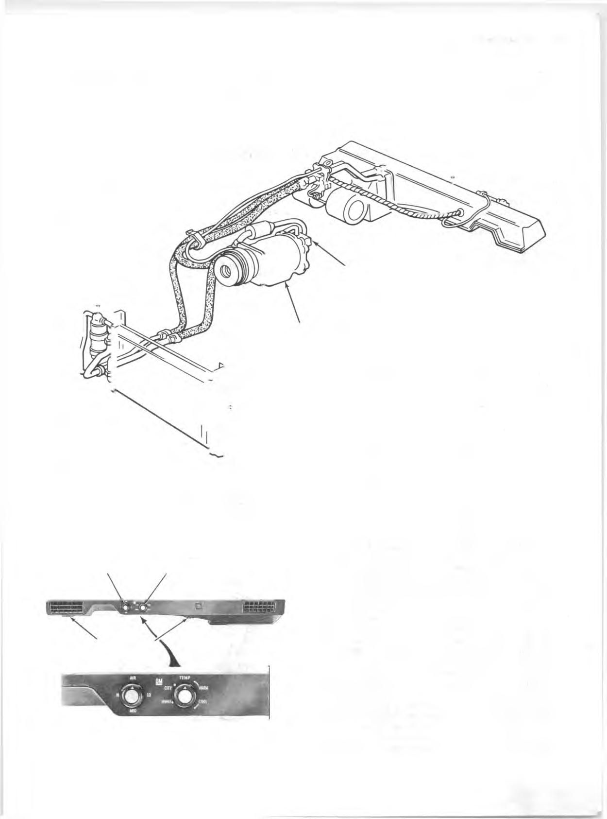
The blow er-evaporator unit is located under the glove com partm ent as indicated in Figure 18. An a ir duct, containing two adjustable outlets and two foot coolers, d eliv ers a ir to the d riv e r's side of the vehicle. The e n tire unit is attached to the instrum ent panel and to the right hand shroud side panel at five locations.
FOOT COOLERS
Fig. 19—G M Chevrolet System Controls CONTROLS (Fig. 19)
System controls are the AIR knob controlling the three speed blower m otor switch and the TEMP knob which controls the setting of the therm ostatic switch. When operating this system , the H eater m ust be fully off for maximum cooling. Air Knob
Turning the AIR knob clockwise operates the three speed blower m otor. Temp Knob
This knob may be regulated to control the degree of
cooling desired. Fully clockwise at CITY provides maximum cooling; however, turning the knob to HIWAY p ro vides adequate cooling for highway operation. NOTE: Reduced cooling could be encountered when operating at highway speeds with the contro ls at the "CITY" setting.
GENERAL INFORMATION
In any vocation or trade, there are established procedures and practices that have been developed after many y e a rs of experience. In addition, occupation hazards may be present that require the observation of certain precautions or use of special tools and equipment. Observing the procedures, practices and precautions of servicing refrigeration equipment will greatly reduce the p o ssibilities of damage to the custom ers' equipment as well as virtually elim inate the element of hazard to the servicem an.
PRECAUTIONS IN HANDLING REFRIGERANT-12
R efrig eran t-12 is tran sp aren t and colorless in both the gaseous and liquid state. It has a boiling point of 21.7° F below zero and, therefore, at all norm al tem peratures and p re ssu re s it will be a vapor. The vapor is heavier than a ir and is noninflammable, nonexplosive, nonpoi- sonous (except when in contact with an open flame) and noncorrosive (except when in contact with water).
W A R N IN G : The following precautions in handling R-12 should be observed at all tim es.

• If it is ever necessary to tran spo rt or ca rry a cylinder or can of refrig eran t in a car, keep it in the luggage com partm ent. R efrigerant should not be exposed to the radiant heat from the sun since the resulting increase in p ressu re may cause the safety valve to release or the cylinder or can to burst. • Cylinders or disposable cans should never be subjected to high tem perature when adding refrig eran t to the system . In most instances, heating the cylinder or can is required to ra ise the p re ssu re in the container higher than the p ressu re in the system during the operation. It would be unwise to place the cylinder on a gas stove, radiator or use a blow torch while preparing for the charging operation, since a serious accident could resu lt. Don't depend on the safety valve - many cylinders have b u rst when the safety valve failed. Remember, high p re ssu re means that great forces are being exerted against the walls of the container. A bucket of warm w ater, not over 125°F, or warm wet rags around the container is all the heat that is required. • Do not weld or steam clean on or near the system .
Welding o r steam cleaning can result in a dangerous p re ssu re buildup in the system . • Discharging large quantities of R-12 into a room can usually be done safely as the vapor would produce no ill effects; however, in the event of an accidental rapid discharge of the system , it is recommended that inhalation of large quantities of R-12 be avoided.
This caution is especially im portant if the area contains a flam e producing device such as a gas heater.
While R-12 norm ally is nonpoisonous, heavy con
centrations of it in contact with a live flame will produce a toxic gas. The sam e gas will also attack all bright m etal surfaces. • Protection of the eyes is of vital importance'. When working around a refrigerating system , an accident may cause liquid refrig eran t to hit the face. If the eyes are protected with goggles or glasses, no serious damage can resu lt. Ju st rem em ber, any
R-12 liquid that you can touch or that touches you is at least 21.7°F, below zero. If a R-12 liquid should strik e the eyes, here is what to do:
1. Keep calm. 2. Do not rub the eyes'. Splash the affected area with quantities of cold water to gradually get the tem perature above the freezing point. The use of mineral, cod liver or an antiseptic oil is im portant in providing a protective film to reduce the possibility of infection. 3. As soon as possible, call or consult an eye specialist for im m ediate and future treatm ent.
PRECAUTIONS IN HANDLING REFRIGERANT LINES
• All m etal tubing lines should be free of kinks, because of the re stric tio n that kinks will offer to the flow of refrigerant. The refrigeration capacity of the entire system can be greatly reduced by a single kink. • The flexible hose lines should never be bent to a radius of less than 10 tim es the diam eter of the hose. • The flexible hose lines should never be allowed to come within a distance of 2-1/2" of the exhaust manifold.
Fig. 20—System Contaminants
• Flexible hose lines should be inspected at least once a year for leaks or brittlen ess. If found brittle or leaking they should be replaced with new lines. • Use only new lines that have been sealed during storing. • When disconnecting any fitting in the refrigeration system , the system m ust fir s t be discharged of all refrig eran t. However, proceed very cautiously r e gardless of gauge readings. Open very slowly, keeping face and hands away so that no injury can occur if there happens to be liquid refrig eran t in the line.
If p re ssu re is noticed when fitting is loosened, allow it to bleed off as described under “ Purging the System ” in this section._______________________________
W A R N IN G : Always w ear safety goggles when opening refrig eran t lines.

• In the event any line is opened in atm osphere, it should be im m ediately capped to prevent entrance of m oisture and dirt. • The use of the proper wrenches when making connections on "O" ring fittings is im portant. The use of im proper wrenches may damage the connection.
The opposing fitting should always be backed up with a wrench to prevent distortion of connecting lines or components. When connecting the flexible hose connections it is im portant that the swaged fitting and the flare nut, as well as the coupling to which it is attached, be held at the sam e tim e using three different wrenches to prevent turning the fitting and damaging the ground seat. • "O" rings and seats must be in perfect condition.
The slightest b u rr or piece of d irt may cause a leak. • Sealing beads on hose clamp connections must be free of nicks and scratch es to assu re a perfect seal.
M AINTAINING CHEMICAL STABILITY IN THE REFRIGERATION SYSTEM
The m etal internal p a rts of the refrigeration system and the re frig eran t and oil contained in the system are designed to rem ain in a state of chem ical stability as long as pure R-12 and uncontaminated refrigeratio n oil is used in the system .
However, when abnormal amounts of foreign m aterials, such as d irt, a ir or m oisture are allowed to enter the sy stem , the chemical stability may be upset. When accelerated by heat, these contaminants may form acids and sludge and eventually cause the breakdown of components within the system . In addition, contaminants m ay affect the te m p e ra tu re-p ressu re relationship of R-12, resulting in im proper operating tem perature and p re s su re s and decreased efficiency of the system .
C A U T IO N : The following general practices should be observed to insure chem ical stability in the system . • Whenever it becom es n ecessary to disconnect a refrig eran t or gauge line, it should be im m ediately capped. Capping the tubing will also prevent d irt and foreign m atter from entering. • Tools should be kept clean and dry. This also includes the gauge set and replacem ent p arts. • When adding oil, the container should be exceptionally clean and dry due to the fact that the re frig e ra tion oil in the container is as m o isture-free as it is possible to make it. T herefore, it will quickly absorb any m oisture with which it comes in contact.
For this sam e reason the oil container should be capped im m ediately after use. • When it is n ecessary to open a system , have everything you will need ready and handy so that as little tim e as possible will be required to perform the operation. Don't leave the system open any longer than is necessary. • Finally, after the operation has been completed and the system sealed again, a ir and m oisture should be evacuated from the system before recharging. J-8393 CHARGING STATION
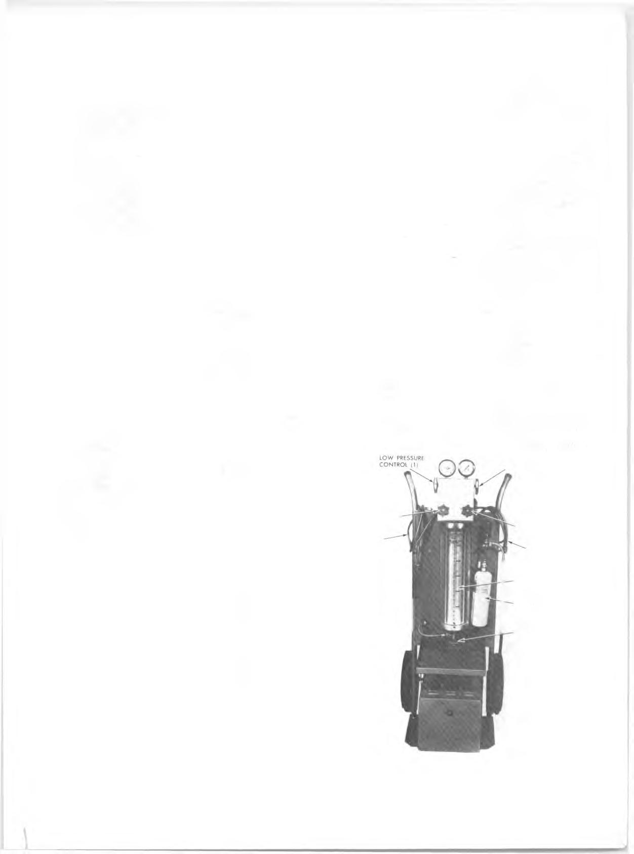
The J-8393 Charging Station is a portable assem bly of a vacuum pump, refrig eran t supply, gauges, valves, and m ost im portant, a five (5) pound m etering refrig eran t charging cylinder. The use of a charging cylinder elim inates the need for scales, hot water pails, etc.
The chief advantage of this unit is savings. A very definite savings in refrig eran t and tim e can be obtained by using this unit. Since the refrigerant is m etered into the system by volume, the c o rrect amount may be added to the system . This, coupled with the fact that the unit rem ains "plumbed" at all tim es and thus elim inates loss of refrig eran t in purging of lines and hooking-up, combines to enable the operator to get full use of all re frig eran t purchased.
All evacuation and charging equipment is hooked together in a compact portable unit (fig. 21). It brings a ir conditioning service down to the basic problem of hooking on two hoses, and manipulating clearly labeled valves.
HIGH PRESSURE CONTROL (2)
VACUUM CONTROL (3)
LOW PRESSURE GAUGE LINE FREON CONTROL (4)
HIGH PRESSURE GAUGE LINE
5 LB. CHARGING CYLINDER
LEAK DETECTOR
FREON DRUM CONTROL VALVE
Fig. 21—J-8393 Charging Station
This will tend to insure that the job will be done without skipping operations. As a resu lt, you can expect to save tim e and get higher quality work, le ss chance of an over or undercharge, or comeback.
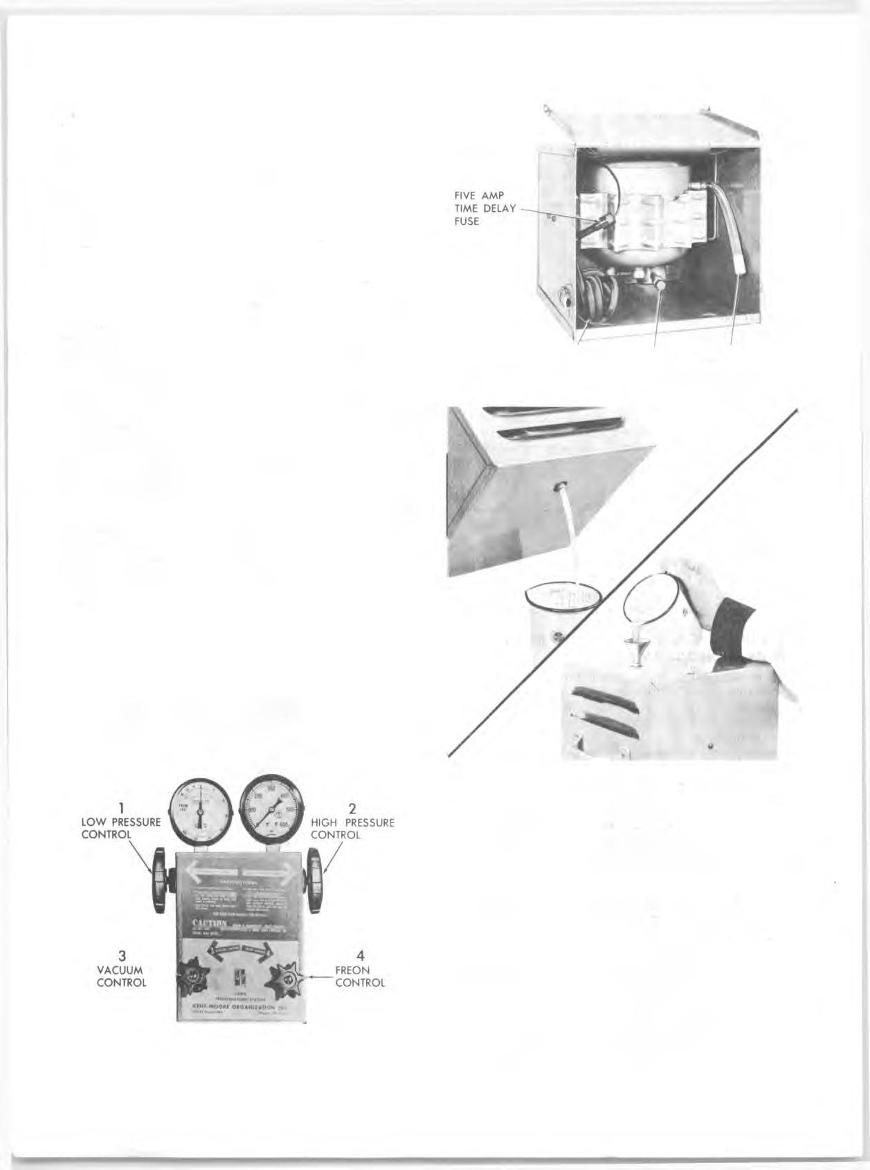
The pump mount is such that the dealer may use his own vacuum pump. The gauges and manifold are in common use. Thus a current a ir conditioning dealer can use the equipment on hand and avoid duplication. GAUGE SET
The gauge set (fig. 22) is an integral p art of the J-8393 Charging Station. It is used when purging, evacuating, charging or diagnosing trouble in the system . The gauge at the left is known as the low p re ssu re gauge. The face is graduated into pounds of p re ssu re and, in the opposite direction, in inches of vacuum. This is the gauge that should always be used in checking p re ssu re s on the low p re ssu re side of the system . When all p a rts of the system are functioning properly the refrig eran t p ressu re on the low p ressu re side never falls below 0 pounds p re s su re. However, several abnorm al conditions can occur th at will cause the low p re ssu re to fall into a p artial vacuum. T herefore, a low p re ssu re gauge is required.
The high p ressu re gauge is used for checking p re s su re s on the high p ressu re side of the system .
The hand shutoff valves on the gauge manifold do not control the opening or closing off of p re ssu re to the gauges. They m erely close each opening to the center connector and to each other. During most diagnosing and service operations, the valves must be closed. Both valves will be open at the sam e tim e during purging, evacuating and charging operations.
The charging station provides two flexible lines for connecting the gauge set to the system components.
VACUUM PUMP
A vacuum pump should be used for evacuating a ir and m oisture from the a ir conditioning system .
The vacuum pump (fig. 23) is a component part of Charging Station J-8393, described previously.
C AU TIO N : The following precautions should be observed relative to the operation and m aintenance of this pump.
Fig. 22—Charging Station Gauge Set
CORD TO PUMP PUMP DISCHARGE 110 AC SO URCE INLET OUTLET
Fig. 23—Vacuum Pump
• Make sure dust cap on discharge outlet of vacuum pump is removed before operating. • Keep all openings capped when not in use to avoid m oisture being drawn into the system . • Oil should be changed after every 250 hours of norm al operation.
To change oil, simply unscrew hex nut located on back side of pump, tilt backward and drain out oil (fig. 23). Recharge with 8 ounces of vacuum pump oil, Frigidaire 150 or equivalent (fig. 23). If you desire to flush out the pump, use the sam e type clean oil. Do not use solvent.
NOTE: Im proper lubrication will shorten pump
life. • If this pump is subjected to extrem e or prolonged cold, allow it to rem ain indoors until oil has reached approximate room tem perature. F ailure to warm oil will resu lt in a blown fuse.
• A five am pere tim e delay cartridge fuse has been installed in the common line to p rotect the windings of the com pressor. The fuse will blow if an excessive load is placed on the pump. In the event the fuse is blown, replace with a five am pere tim e delay fuse - do not use a substitute fuse as it will resu lt in damage to the starting windings. • If the pump is being utilized to evacuate a burnt-out system , a filte r m ust be connected to the intake fitting to prevent any sludge from contaminating the working p a rts, which will resu lt in malfunction of the pump. • Do not use the vacuum pump as an a ir com pressor.
LEAK TESTING THE SYSTEM
W henever a refrig eran t leak is suspected in the system or a service operation perform ed which resu lts in disturbing lines or connections, it is advisable to test for leaks. Common sense should be the governing factor in perform ing any leak te st, since the necessity and extent of any such te st will, in general, depend upon the nature of the complaint and the type of service perform ed on the system . C A U T IO N : The use of a leak detecting dye with- in the system is not recom m ended because of the following reasons! 1. R efrigerant leakage can exist without any oil leakage.
In this case the dye will not indicate the leak, however, a torch detector will. 2. The addition of additives, other than inhibitors, may a lte r the stability of the refrigeration system and cause malfunctions. 3. Dye type leak detectors, which are insoluble, form a curdle which can block the inlet screen of the expansion valve. Leak Detector
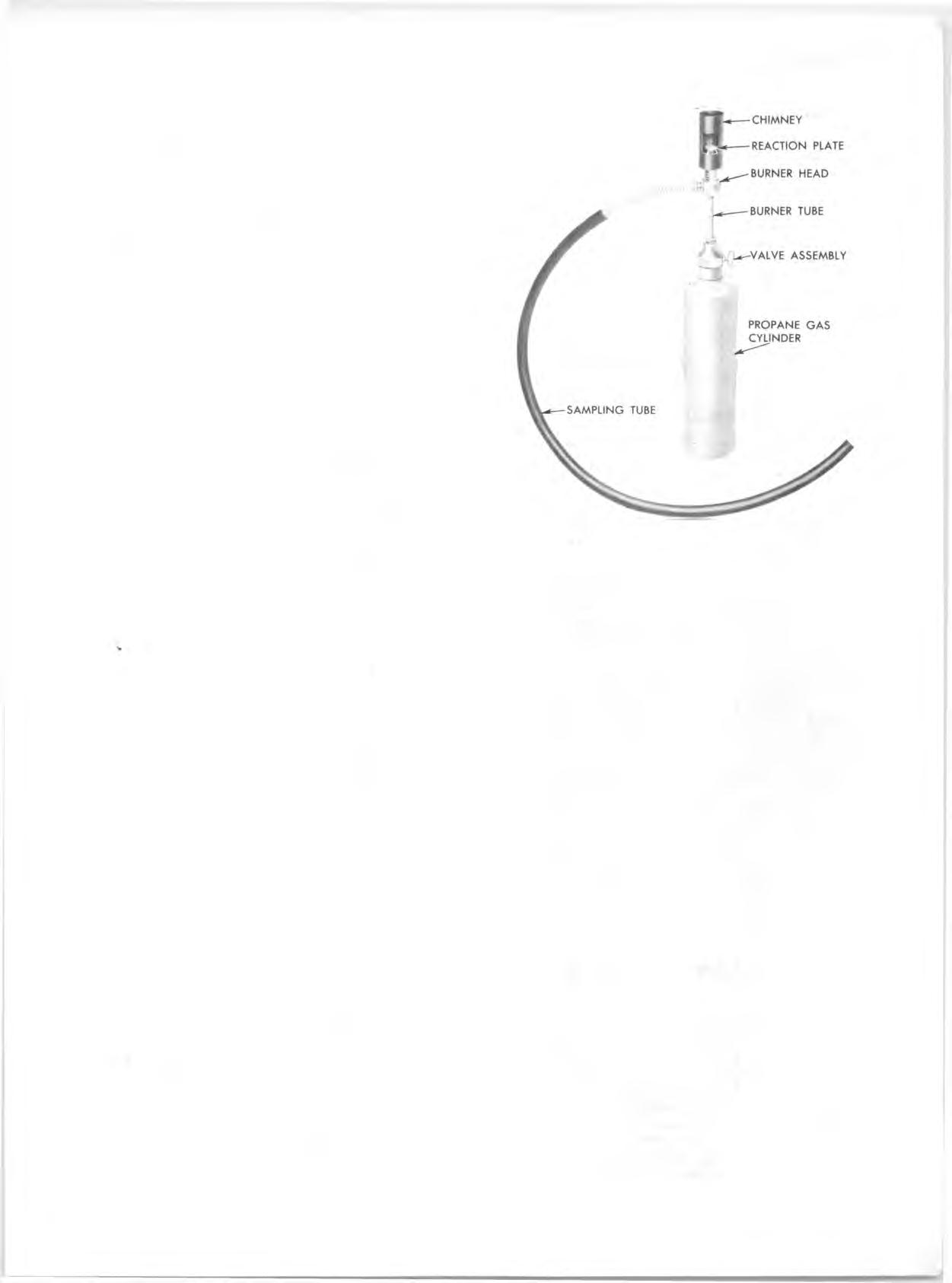
Tool J-6084 (fig. 24) is a propane gas-burning torch which is used to locate a leak in any p art of the system . R efrigerant gas drawn into the sampling tube attached to the torch will cause the torch flam e to change color in proportion to the size of the leak. Propane gas fuel cylinders used with the torch are readily available comm ercially throughout the country. W A R N IN G : Do not use lighted detector in any place where combustible or explosive gases, dusts or vapors may be present.
Operating Detector
1. Determ ine if there is sufficient refrig eran t in the system for leak testing. 2. Open control valve only until a low hiss of gas is heard, then light gas at opening in chimney. 3. Adjust flame until desired volume is obtained. This is m ost satisfactory when blue flam e is approxim ately 3/8" above reacto r plate. The reacto r plate will quickly heat to a cherry red. 4. Explore for leaks by moving the end of the sampling hose around possible leak points in the system . Do not pinch or kink hose.
NOTE: Since R-12 is heavier than a ir, it is good practice to place open end of sampling tube
Fig. 24—Leak Detector
im m ediately below point being tested, p articularly in cases of sm all leaks.
W A R N IN G : Do not breathe the fumes that are produced by the burning R-12 gas in the detector flame, since such fumes can be toxic in large concentrations of R-12. 5. Watch for color changes. The color of the flame which passes through the reaction plate will change to green or yellow -green when sampling hose draws in very sm all leaks of R-12. Large leaks will be indicated by a change in color to a b rilliant blue or purple. When the sampling hose p asses the leak, the flame will clear to an alm ost colorless pale blue again. O bservations are best made in a sem idarkened area. If the flame rem ains yellow when unit is removed from leak, insufficient a ir is being drawn in or the rea cto r plate is dirty.
NOTE: A re frig eran t leak in the high p re ssu re side of the system may be more easily detected if the system is operated for a few m inutes, then shut off and checked im m ediately (before system p re ssu re s equalize). A leak on the low p re ssu re side may be more easily detected after the engine has been shut off for several minutes (system p re ssu re s equalized); this applies p a rticularly to the front seal.
AVAILABILITY OF REFRIGERANT-12
R efrigerant 12 is available in 30 lb. and in 15 oz. disposable containers.
Norm ally, air conditioning system s are charged making use of the J-8393 Charging Station which uses the 30 lb- container. Evacuating and Charging Procedures are noted la te r in this section.
The 15 oz. disposable cans a re generally used for m iscellaneous operations such as flushing.