7 minute read
Motor Home C hassis


COMPRESSOR OIL
Special refrigeration lubricant should be used in the system . This oil is as free from m oisture and contam inants as it is possible to attain by human processes. This condition should be p reserv ed by immediately capping the bottle when not in use.
See "A ir Conditioning System Capacities" for the total system oil capacity.
Due to the porosity of the refrig eran t hoses and connections, the system refrig e ran t level will show a definite drop after a period of tim e. Since the com pressor oil is c a rrie d throughout the entire system mixed with the refrig eran t, a low refrig eran t level will cause a dangerous lack of lubrication. Therefore the refrig eran t charge in the system has a definite tie-in with the amount of oil found in the com pressor and an insufficient charge may eventually lead to an oil build-up in the evaporator.
COMPRESSOR SERIAL NUMBER
The com pressor se ria l number is located on the serial num ber plate on top of the com pressor. The se rial numb e r consists of a se rie s of num bers and le tte rs. This se ria l number should be referenced on all form s and correspondence related to the servicing of this part.
INSPECTION AND PERIODIC SERVICE
PRE-DELIVERY INSPECTION
1. Check that engine exhaust is suitably ventilated. 2. Check the belt for proper tension. 3. With controls positioned for operation of the system , operate the unit for ten minutes at approximately 2000 rpm . Observe the clutch pulley bolt to see that the com pressor is operating at the sam e speed as the clutch pulley. Any speed variation indicates clutch slippage. 4. Before turning off the engine, check the sight glass to see that the unit has a sufficient R efrigerant charge. The glass should be clear, although during m ilder weather it may show tra c e s of bubbles. Foam in the flow indicates a low charge. No liquid visible and no tem perature differential between com pressor inlet and outlet lines, indicates no charge. 5. Check refrig eran t hose connections: "O" ring Connections - Check torque of fittings as charted later in this section under "R efrigerant Line
Connections;" retorque if required. Leak te st the complete system .
Hose Clamp Connections - If clamp screw torque is le ss than 10 in. lb., retighten to 20-25 in. lbs. Do not tighten to new hose specifications or hose leakage may occur. Leak test the complete system . 6. If there is evidence of an oil leak, check the comp re sso r to see that the oil charge is satisfactory.
NOTE: A slight amount of oil leakage at the com pressor front seal is considered norm al. 7. Check the system controls for proper operation.

6000 MILE INSPECTION
1. Check unit for any indication of a refrig eran t leak. 2. If there is an indication of an oil leak, check the com pressor for proper oil charge.
NOTE: A slight amount of oil leakage at the com pressor front seal is considered normal. 3. Check sight glass for proper charge of R efrigerant-12. 4. Tighten the com pressor brace and support bolts and check the belt tension. 5. Check refrig eran t hose connections as in Step 5 of "P re-D e liv ery Inspection.”
PERIODIC SERVICE
• Inspect condenser regularly to be sure that the fins are not plugged with leaves or other foreign m aterial. • Check evaporator drain tubes regularly for d irt or restrictio n s. • At least once a year, check the system for proper refrig eran t charge and the flexible hoses for b rittle ness, w ear or leaks. • Every 6000 m iles check sight glass for low re frig erant level. • Check belt tension regularly.
EVACUATING AND CHARGING PROCEDURES
AIR CONDITIONING SYSTEM CAPACITY
R efrigerant Charge Oil Charge Four-Season System 3 lbs. 4 oz. 10 oz. 525 Viscosity
Roof-Mounted 5 lbs. 8 oz. 13 oz. 525 Viscosity
GM Chevrolet 3 lbs. 4 oz. 10 oz. 525 Viscosity INSTALLING CHARGING STATION
1. High and low p re ssu re gauge line fittings are provided in the a ir conditioning system for attaching the
Charging Station.
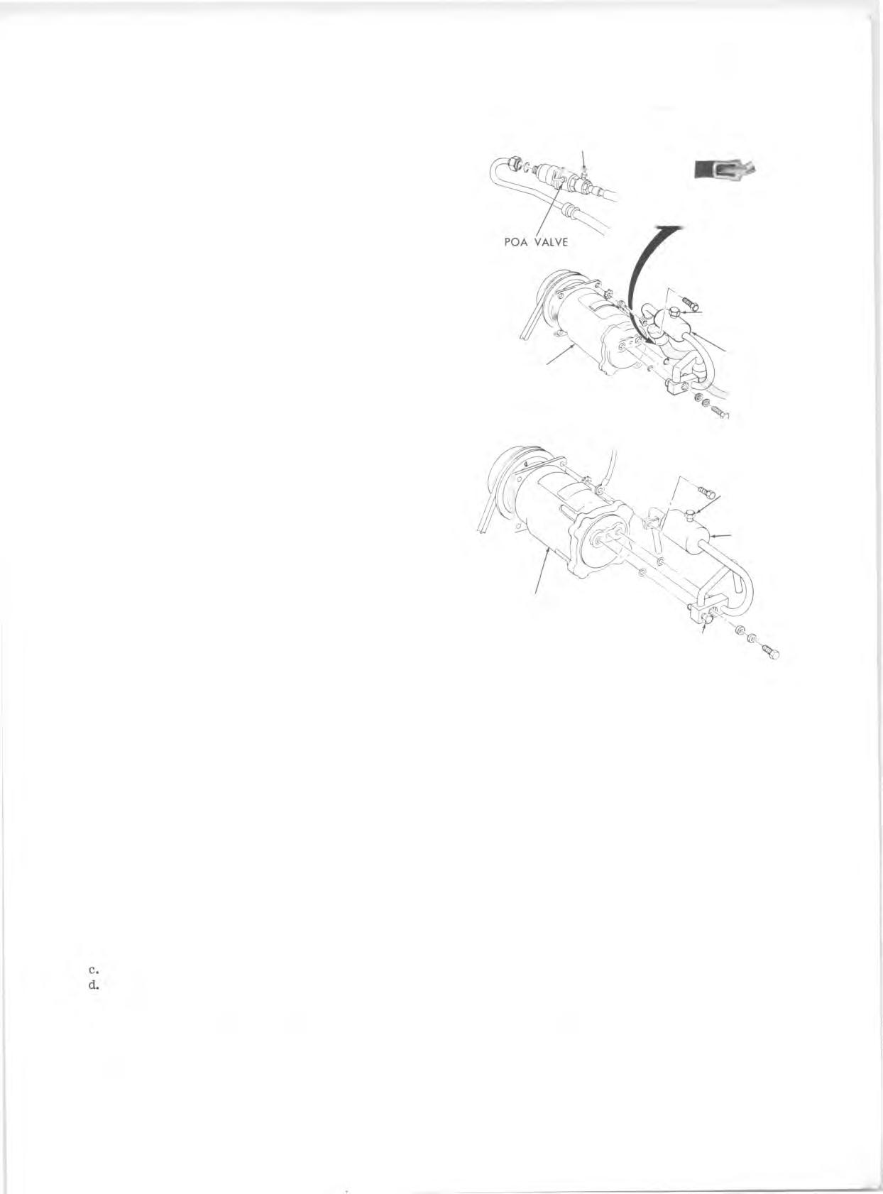
Four-Season and Roof Mounted System s— The low p re ssu re fitting is located on the POA valve. The high p re ssu re fitting is located on the muffler (fig. 25).
NOTE: The connector assem bly consists of inlet (suction) and outlet (discharge) lines with the freon hoses swaged to the m etal lines.
GM Chevrolet System s—The low p re ssu re fitting is located on the connector block and the high p re ssu re fitting on the m uffler (fig. 25). 2. Install Gauge Adapters J-5420 and J-9459 onto the high and low p re ssu re gauge lines. 3. With the engine stopped, remove the caps from the cored valve gauge fittings. 4. Be certain all valves on charging station are closed. 5. Connect high p re ssu re gauge line to high p ressu re gauge fitting. 6. See Figure 22. Turn high p re ssu re control (2) one turn counter-clockw ise (open). C rack open low p re ssu re control (1) and allow refrig eran t gas to hiss from low p ressu re gauge line for three seconds, then connect low p re ssu re gauge line to low p re ssure gauge fitting. 7. System is now ready for purging or perform ance testing.
PURGING THE SYSTEM
In replacing any of the a ir conditioning components the system must be completely purged or drained of r e frigeran t. The purpose is to lower the p re ssu re inside the system so that a component p art can be safely r e moved. 1. With engine stopped, in stall high and low p ressu re lines of Charging Station gauge set to the proper high and low p ressu re gauge fittings. (See “ Installing
Charging Station” )
C AU TIO N : Before installing lines, be sure that all four controls on the gauge set are closed. 2. Disconnect vacuum line at Charging Station vacuum pump and put the line in a covered can as shown in
Figure 27.
NOTE: An empty 3 lb. coffee can with a plastic cover which has been c ro s s -s lit (X’ed), to allow hose entry, works well for this purpose. 3. Fully open high (2) and low (1) p ressu re control valves, and allow re frig eran t to purge from system at a rapid rate into the covered can. 4. Oil loss will be m inimal. It may be added to the system during evacuation as described later. 5. Toward the end of the purge stage, Tool J-24095 should be flushed with refrig eran t to eliminate possible contamination. a. Disconnect re frig eran t line at supply tank. b. Flush Tool J-24095 by cracking valve on re frig erant tank. Close valve after flushing for approxim ately three seconds. T em porarily refasten the tool. Reconnect refrig eran t line to supply tank.
EVACUATING AND CHARGING THE SYSTEM
GENERAL NOTE: In all evacuating procedures shown below, the specification of 28-29 inches of M ercury vacuum is used. These figures are only attainable at or near Sea Level Elevation.
LOW PRESSURE FITTING
SW A G ED FITTING
COMPRESSOR HIGH PRESSURE FITTING
MUFFLER
FOUR-SEASON AND ROOF-MOUNTED SYSTEM
HIGH PRESSURE
FITTING
MUFFLER
COMPRESSOR
LOW PRESSURE FITTING
G M CHEVROLET SYSTEM
Fig. 25—Compressor Connector Block - Typical
For each 1000 feet above sea level where this operation is being perform ed, the specifications should be lowered by 1 inch. Example: at 5000 ft. elevation, only 23 to 24 inches of vacuum can norm ally be obtained.
Whenever the a ir conditioning system is open for any reason, it should not be put into operation again until it has been evacuated to remove a ir and m oisture which may have entered the system .
The following procedures are based on the use of the J-8393 Charging Station.
Adding Oil
If necessary, refrig eran t oil may be added to the sy stem by the following procedure: 1. Install charging station and purge system as p re viously described. 2. A fter system has been purged, connect the vacuum line to the vacuum pump. 3. M easure oil loss collected as a resu lt of purging the system .