
2 minute read
Engine Oil SAE Below Freezing


Engine coolant constantly flows through the heater core during engine operation. Heater output is adjusted by varying the airflow and air temperature through the system. A dash mounted three lever control system is employed. One lever controls the heater-defroster air deflector. The second lever opens the air door and operates the three speed fan switch. The third lever operates a temperature door which passes the airflow either through the heater core, around the core, or partially through and partially around the core.
CONTROLS
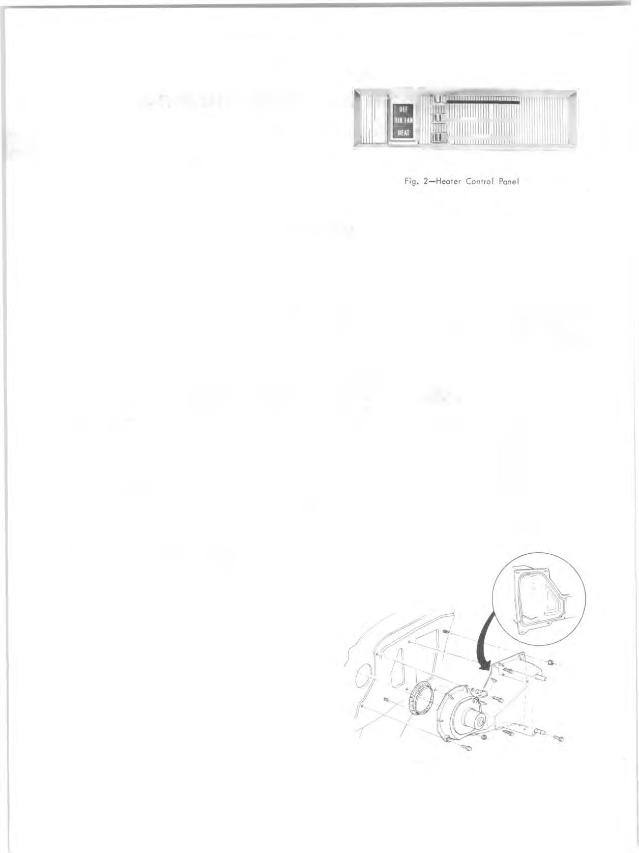
The heater controls are located in the center of the dash, below the ash tray. In operation, three levers control all heater operations (fig. 2).
DEF Lever
Moving the DEF (defroster) lever to the right moves an air deflector in the distributor duct which channels the airflow partially or fully to the defroster air outlets.
A IR -F A N Lever
When this lever is fully left, no air passes through the system. Moving the lever to the right about one-third of its travel opens the air door in the air distributor duct. Moving the lever further to the right operates the three speed blower switch.
HEAT Lever
When this lever is fully left, the temperature door in the blower duct causes the airflow to bypass the heater core. Moving the lever to the right moves the temperature door allowing some air to pass through the core and some to bypass the core. With the lever fully right, all air flowing through the system passes through the core.
C O M P O N E N T R EP LA C E M EN T A N D REPAIR
BLOWER A SSEM BLY
Removal
1. Disconnect battery ground cable. 2. Support the right front of the hood in the fully raised position. 3. Carefully scribe the hood and fender locations of the right hood hinge and remove the hinge. 4. Unclip the blower wire at the blower flange terminal and note or mark the motor flange position in relation to the blower case. 5. Remove the blower assembly mounting screws. 6. Remove the blower assembly (pry the flange away from the case carefully if the sealer acts as an adhesive). 7. Remove the nut attaching the blower wheel to the motor shaft and separate the assembly.
Installation
1. Assemble the blower wheel to the motor with the open end of the blower away from the motor. 2. Install the assembly to the blower case, connect ground strap, and connect the motor wire. 3. Remount the hood hinge aligning it carefully with the scribed lines. Check hood alignment. 4. Connect battery ground cable.
BLOWER, CO RE CA SE A N D CO RE A SSEM BLY
Removal (Fig. 3)
1. Drain radiator. 2. Disconnect battery ground cable. 3. Unclip the blower motor wire at the blower flange terminal. 4. Disconnect heater hoses at the core tubes (fig. 4). 5. (Under dash) Remove the seal on the termperature door cable at the distributor duct adapter and disconnect the cable from the temperature door. 6. In order to gain access to the lower outboard case attachments, the right front fender skirt should be loosened and moved,, Remove enough skirt mounting screws and bolts (from the rear forward) to move the skirt a sufficient amount. 7. Support the right front of the hood in the fully raised
Fig. 3 — Heater Assem bly