6 minute read
Motor Home Chassis


The pump mount is such that the dealer may use his own vacuum pump. The gauges and manifold are in common use. Thus a current air conditioning dealer can use the equipment on hand and avoid duplication.
G A U G E SET
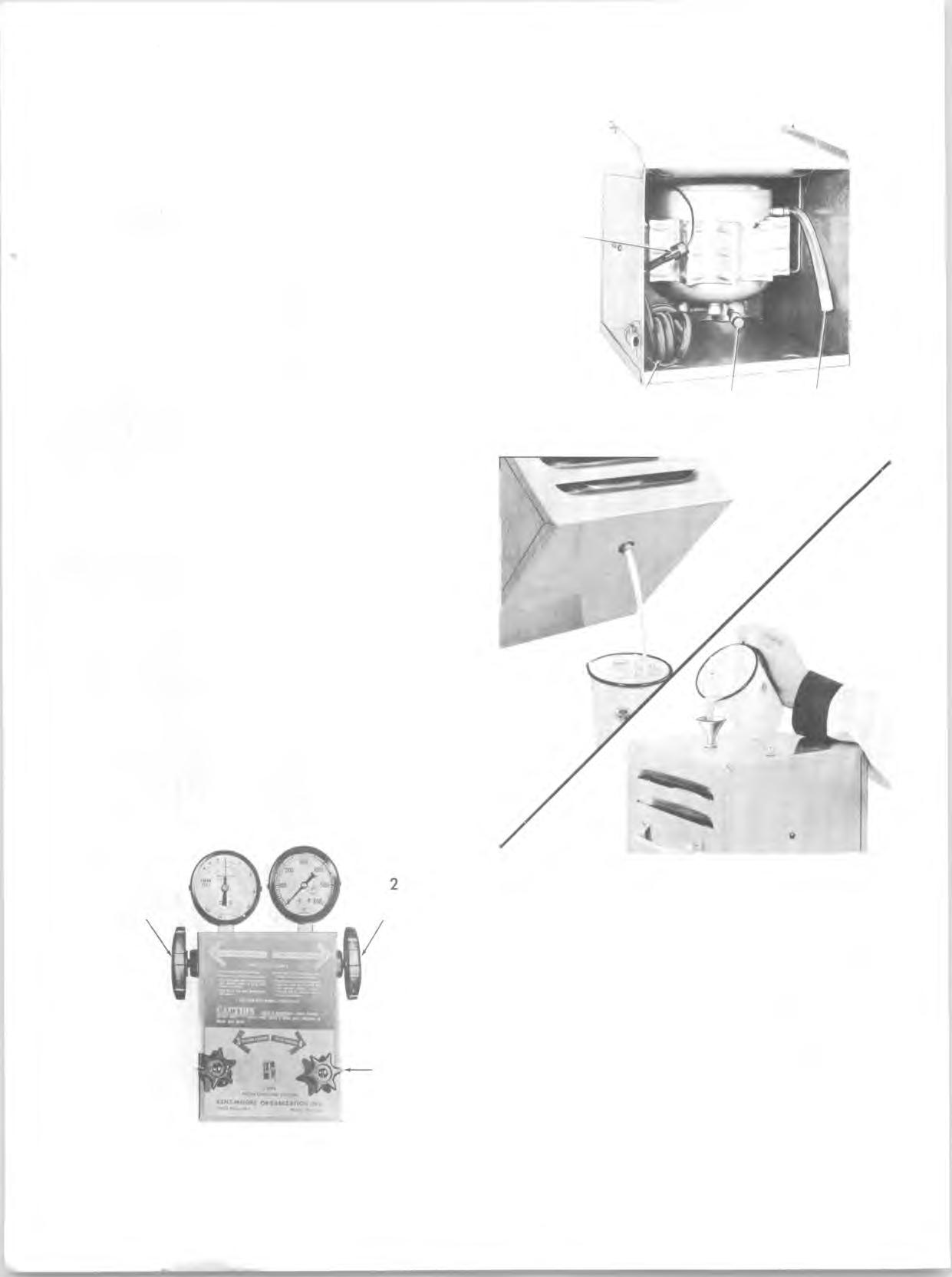
The gauge set (fig. 22) is an integral part of the J-8393 Charging Station. It is used when purging, evacuating, charging or diagnosing trouble in the system. The gauge at the left is known as the low pressure gauge. The face is graduated into pounds of pressure and, in the opposite direction, in inches of vacuum. This is the gauge that should always be used in checking pressures on the low pressure side of the system. When all parts of the system are functioning properly the refrigerant pressure on the low pressure side never falls below 0 pounds pressure. However, several abnormal conditions can occur that will cause the low pressure to fall into a partial vacuum. Therefore, a low pressure gauge is required.
The high pressure gauge is used for checking pressures on the high pressure side of the system.
The hand shutoff valves on the gauge manifold do not control the opening or closing off of pressure to the gauges. They merely close each opening to the center connector and to each other. During most diagnosing and service operations, the valves must be closed. Both valves will be open at the same time during purging, evacuating and charging operations.
The charging station provides two flexible lines for connecting the gauge set to the system components.
V A C U U M PUMP
A vacuum pump should be used for evacuating air and moisture from the air conditioning system.
The vacuum pump (fig. 23) is a component part of Charging Station J-8393, described previously. The following precautions should be observed relative to the operation and maintenance of this pump. • Make sure dust cap on discharge outlet of vacuum pump is removed before operating. • Keep all openings capped when not in use to avoid moisture being drawn into the system.
1
FIVE A M P T IM E D E L A Y FUSE
C O R D T O P U M P P U M P D IS C H A R G E 1 1 0 A C S O U R C E INLET O UTLET
L O W P R E SSU R E C O N T R O L H IG H P R E SS U R E C O N T R O L
3
V A C U U M C O N T R O L
4
F R E O N C O N T R O L
Fig. 2 2 — C h a rgin g Station G a u ge Set
Fig. 23— Vacuum Pu mp
• Oil should be changed after every 250 hours of normal operation.
To change oil, simply unscrew hex nut located on back side of pump, tilt backward and drain out oil (fig. 23). Recharge with 8 ounces of vacuum pump oil, Frigidaire 150 or equivalent (fig. 23). If you desire to flush out the pump, use the same type clean oil. Do not use solvent.
NOTE: Improper lubrication will shorten pump life. • If this pump is subjected to extreme or prolonged cold, allow it to remain indoors until oil has reached approximate room temperature. Failure to warm oil will result in a blown fuse.
• A five ampere time delay cartridge fuse has been installed in the common line to protect the windings of the compressor. The fuse will blow if an excessive load is placed on the pump. In the event the fuse is blown, replace with a five ampere time delay fuse - do not use a substitute fuse as it will result in damage to the starting windings. • If the pump is being utilized to evacuate a burnt-out system, a filter must be connected to the intake fitting to prevent any sludge from contaminating the working parts, which will result in malfunction of the pump. • Do not use the vacuum pump as an air compressor.

LEAK TESTING THE SYSTEM
Whenever a refrigerant leak is suspected in the system or a service operation performed which results in disturbing lines or connections, it is advisable to test for leaks. Common sense should be the governing factor in performing any leak test, since the necessity and extent of any such test will, in general, depend upon the nature of the complaint and the type of service performed on the system.
NOTE: The use of a leak detecting dye within the system is not recommended because of the following reasons: 1. Refrigerant leakage can exist without any oil leakage.
In this case the dye will not indicate the leak, however, a torch detector will. 2. The addition of additives, other than inhibitors, may alter the stability of the refrigeration system and cause malfunctions. 3. Dye type leak detectors, which are insoluble, form a curdle which can block the inlet screen of the expansion valve.
Leak Detector
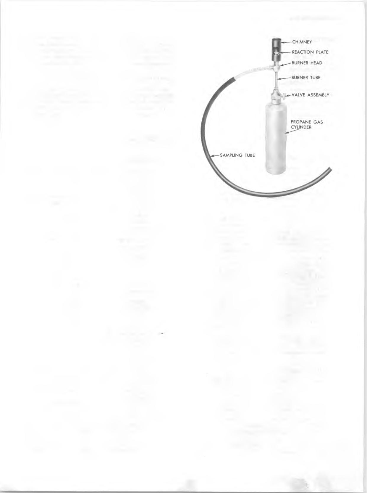
Tool J-6084 (fig. 24) is a propane gas-burning torch which is used to locate a leak in any part of the system. Refrigerant gas drawn into the sampling tube attached to the torch will cause the torch flame to change color in proportion to the size of the leak. Propane gas fuel cylinders used with the torch are readily available commercially throughout the country.
CAUTION: Do not use lighted detector in any place where combustible or explosive gases, dusts or vapors may be present.
Operating Detector
1. Determine if there is sufficient refrigerant in the system for leak testing. 2. Open control valve only until a low hiss of gas is heard, then light gas at opening in chimney. 3. Adjust flame until desired volume is obtained. This is most satisfactory when blue flame is approximately 3/8” above reactor plate. The reactor plate will quickly heat to a cherry red. 4. Explore for leaks by moving the end of the sampling hose around possible leak points in the system. Do not pinch or kink hose.
NOTE: Since R-12 is heavier than air, it is good practice to place open end of sampling tube
Fig. 24—-Leak Detector
immediately below point being tested, particularly in cases of small leaks.
CAUTION: Do_ not breathe the fumes that are produced by the burning R-12 gas in the detector flame, since such fumes can be toxic in large concentrations of R-12. 5. Watch for color changes. The color of the flame which passes through the reaction plate will change to green or yellow-green when sampling hose draws in very small leaks of R-12. Large leaks will be indicated by a change in color to a brilliant blue or purple. When the sampling hose passes the leak, the flame will clear to an almost colorless pale blue again. Observations are best made in a semidarkened area. If the flame remains yellow when unit is removed from leak, insufficient air is being drawn in or the reactor plate is dirty.
NOTE: A refrigerant leak in the high pressure side of the system may be more easily detected if the system is operated for a few minutes, then shut off and checked immediately (before system pressures equalize). A leak on the low pressure side may be more easily detected after the engine has been shut off for several minutes (system pressures equalized); this applies particularly to the front seal.
AVA ILABILITY OF REFRIGERANT-12
Refrigerant 12 is available in 30 lb. and in 15 oz. disposable containers.
Normally, air conditioning systems are charged making use of the J-8393 Charging Station which uses the 30 lb- container. Evacuating and Charging Procedures are noted later in this section.
The 15 oz. disposable cans are generally used for miscellaneous operations such as flushing.