Universal Type Cables (XX) Indicate the cable length you require in feet - AQMC8(08) = AQMC8 (8ft cable)
Mid range cable for longer more complicated routes
How to measure for a Replacement Control Cable Control cable length in feet. Round up up to next even foot.
For new installation Outboards
Cable length: measure cable path, add 3ft for engine loop. Round up to next even foot.
For Replacement of Existing Cable:
For new installation Sterndrive Inboards
Typical stern drive inboard control cable routing. Cable length: measure cable path and round up to next even foot.
If you have removed the old cable, measure the cable as follows: from tip to tip and round up to the next foot. The control cable part number contains its length. AquaFlex cables are usually listed as AQMC??XX, where XX = length in feet. FOR EXAMPLE: Part Number AQMC828 = 28 ft.
CONTROL CABLE LENGTH IN FEET
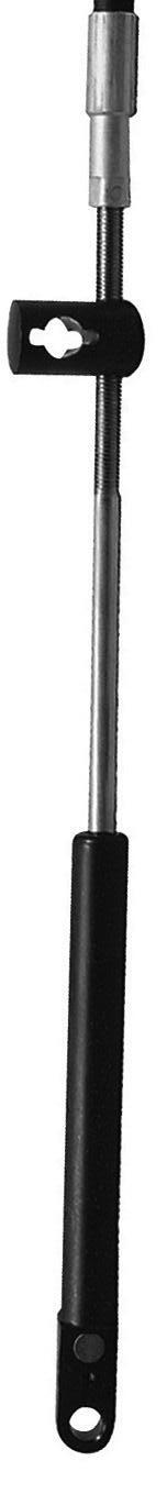
AquaFlex C8 Standard Engine Control Cable
¡ Single steering station only
¡ Engine control cables for use with all inboard and the following sterndrive and outboard engines
OEM TYPE REPLACEMENT CONTROL CABLE SELECTION CHART
For Replacement of Existing Cable:
If you have removed the old cable, measure the cable as follows: from tip to tip and round up to the next foot. The control cable part number contains its length. AquaFlex cables are usually listed as AQM??XX, where XX = length in feet. FOR EXAMPLE: Part Number AQMC1420 = 20 ft.
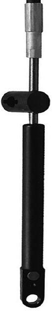
AquaFlex C5 Engine Control Cable
¡ Engine
and Mercruiser® engines
¡ Conduit
¡ Jacket colour:
¡ Stroke: 95mm (3.75”)
OEM Engine Control Cables
AquaFlex C36 Engine Control Cable
¡
Engine Control Cables
What kind of control cables go on my boat? The boat has a [brand name] engine.
There are several ways to determine this information by noting:
a. appearance of the cable
b. part number of the cable
c. engine(s) and controls on which cable is used
Take a look at the existing cable.
Usually, the part number is stamped in white on the existing cable’s plastic outer casing.
If you can’t locate it or read the part number, check to see what brand of control and brand/year of engine is on the boat.
With this information, you can determine which cable you need from identification/application information.
What kind of ongoing maintenance do cables need? Can they be repaired?
We suggest the following periodic maintenance be performed at least twice a season:
a. Check overall operation for proper gear engagement, full and idle throttle, and overall feel.
b. Visually inspect control head cable, as well as engine and transmission cable attachment points for proper tightness of fasteners, correct operation of all moving parts, worn or broken items, cable chafing or misalignment, etc.
c. Do not lubricate core wire (moving wire inside the casing). If the cable operates stiffly, replace it.
d. Keep cable ends dirt and corrosion free.
e. Lubricate pivot points and sliding parts of the cable with a good quality, water-resistant grease.
When to replace a cable or connection hardware:
a. Excessive free play felt at the control even after all cable connections have been verified as in good working order.
b. Visual inspection shows signs of chafing, breakage, bent, loose or worn parts.
Never attempt to repair a cable. Always replace a malfunctioning cable. A cable cannot be properly repaired in the field and must always be replaced as an assembly. Attempting to repair a cable can result in control system failure, leading to personal injury and/or property damage.
What purpose do control cables serve?
Control cables operate the throttle and gear shift between the control box and engine.
Are outboard control cables universal?
Replacement throttle cables for Mercury®, Mariner® and Evinrude® outboard engines and MerCruiser® inboard engines are generally OEM type cables (C5, C14 & C36) with special end fittings designed to connect to the control box and engine with minimal hardware. Generally, all other engines and control boxes use a “universal” C8 type control cable. For heavier duty applications use a C22 cable.
I have bought a C8 cable, how do I connect it to the engine and control box?
Depending on the condition of the old cable end connectors, they can be removed from the old cable and fitted to the new cable. If the old connectors are not suitable to be reused, consult your local dealer.
How can I check if the old cable ends can be reused?
Start by checking no deterioration to the plastic or metal clip. If this is ok, check there is no damage to the internal thread.
I have a non-genuine manufacturer control box, what cable and cable end do I need?
You will need a C8 cable. For the cable ends you will need to consult with the local engine dealer.
The control cable I have is too long, can I shorten it?
There is no known method of changing the length of a mechanical control cable. Your best option is to purchase new cables of the proper length.
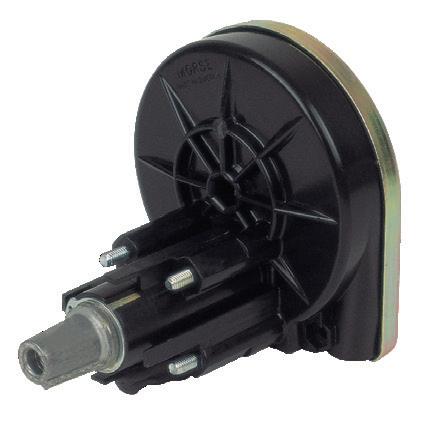
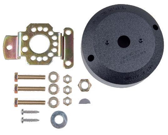
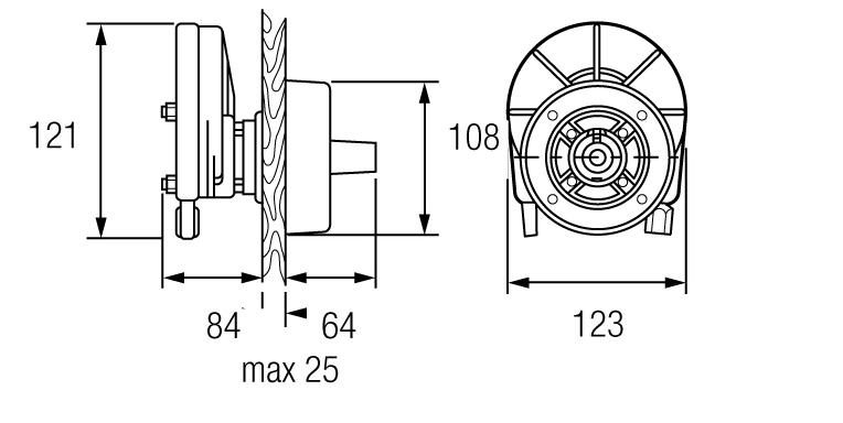
AquaFlex Steering Helm
¡ 2.6 turns lock to lock
¡ Compact fit behind bulkhead
¡ Externally adjustable damper
¡ Variable cable approach
¡ Includes 90° bezels
¡ For outboard engines up to 53hp
¡ 3/4” tapered steering shaft
FAQ’s
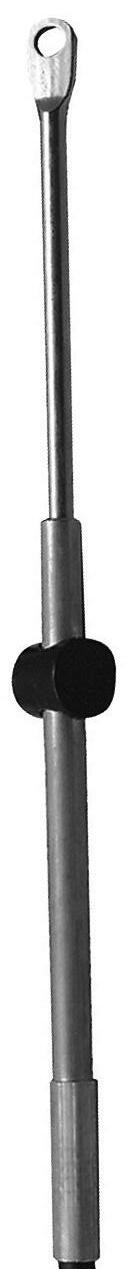
AquaFlex M58 Steering Cables
¡ Steering cable for AquaFlex Steering Helm, Ultraflex Compac-T and Seastar SH8050, C230/231 helms
¡ Conduit OD: 13mm
¡ Jacket colour: Black
¡ Thread end: Nut 7/8” UNF
¡ Inner wire: 6mm
¡ A range of light duty steering cables suitable for boat engines under 55HP
¡ Designed for use with most marine applications from outboard to inboard, making light work of steering in all conditions
How do I know which length
steering cable I need?
The cable part number and length can usually be found about 2 feet from one end of the cable, stamped into the plastic conduit (exterior jacket or casing). If you can’t locate/read it, proceed to step a:
a. Is the cable you are replacing rotary?
Rotary is a spiral wrapped black core wire that sticks out at helm end of cable. The rack and pinion cable has long metal housing with rack [flat] gear inside (under the dash).
Measure the cable’s plastic jacket (casing) in inches. If rotary, add 18” and round up to the next foot. If rack & pinion, add 30” and round up to the next foot. Order that length cable.
b. Are you doing a first-time steering cable installation?
Measure cable routing path in boat as follows:
A = Centre line of wheel to gunwale (inches),
B = Dash to transom (inches),
C = Gunwale to cable connection at centred tiller (inches).
For Tilt Tube Mounting, add A, B & C + 6”, and round up to the next foot. Order that length cable. For Transom/Splashwell/ Stringer Support Mounting, add A, B & C, then subtract 6” and round up to the next foot. Order that length cable.
The steering cable’s “core wire” is broken. How can this be repaired?
Steering cables cannot be repaired.
If a steering cable inner core wire separates or breaks within the steering helm (gear box), the steering cable must be replaced with the correct one for the helm.
The helm may need to be replaced as well. Cable breakage within the helm may have caused damage to the gears. A helm cannot be repaired and must be replaced as a unit.
How to Measure Steering Cables “MEASURE TWICE. ORDER ONCE.”
Replacement of Existing Rotary Steering Cable:
If possible, find the part number stamped on the plastic jacket of the old cable. If you removed the old cable, measure for the replacement cable as follows:
Measure the plastic cable jacket (Y) in inches, then, add 18 inches to this measurement. Now round this measurement up to the nearest foot. Check the helm and cable type and order that length of cable.
New Installation:
Measure cable routing path from wheel centre line to engine connection, as follows:
A = Centre line of wheel to gunwale (or deck, if routed downward),
B = Dash to transom,
C = Gunwale to centreline of cable connection at centred tiller.
For cable installations through the engine tilt tube: add A, B & C + 6”, and round up to the next foot. Order that length cable.
For cables mounted to transom, splashwell or stringer: add A, B & C, then subtract 6” and round up to the next foot. Order that length cable.
THROUGH ENGINE TILT TUBE
A single-cable, starboard drive push-pull mechanical cable system is shown in this diagram. If your mechanical system is different than the one depicted and/or you have any questions about mechanical steering after reviewing this guide, please contact Bainbridge.