
PORTFOLIO
INTRODUCTION
TEAM&ZONE
ISO19650
VIADUCT
STATIONDRAWINGS
REBARDETAILS
FAMILYCREATION
CDE
CLASHDETECTION
4DSIMULATION
5DQUANTIFICATION
PROJECTLEARNINGS
INTRODUCTION
JAKARTAMRT
PROJECTBRIEF:
Involves the intricate design of stations along the stretch between Senayan and Pancoran for the Light Rail Transit (LRT) system , coupled withtheimplementationofaviaducttosupporttheJakartamassrapid transit (MRT) line. This endeavor requires meticulous planning , precise engineering,andseamlesscoordinationofvariousstakeholderstoensure the successful integration of both systems, enhancing the connectivity andefficiencyofJakarta’spublictransportationnetwork.
Projectdetails:
Location:Senayan&Pancoran,southJakarta,Indonesia.
StationGrossArea:11500Sq.m
ViaductLength:15km
No.ofMetroStation:6
FirstStation:Senayan
LastStation:Pancoran
LevelofDetail:350

TEAM&ZONE:
The concepts of teams and zones plays a crucial role in optimizing productivity,with6stationsstrategicallydividedinto3zones,eachfacilitated by2teammembers.Bystructingourworkflowinthismanner,weenhance productivityandpromoteeffectivecommunicationamongteammembers, fosteringaprofessionalenvironmenttowardssuccess.


STAGESOFISO19650:
Establishingproject understandingand identifying stakeholders.
Appointingparty createstender docsforproject bidding.
Possibleappointed partyprepare actionplan.
Leadappointed partyisappointed andtheystarttheir work.
VIADUCTALIGNMENT:
AspartofalargeprojecttobuildtheMRTnetworkbetween Senayan Metro and Pancoran LRT stations, is involves constructingsixnewmetrostationswithinthenetwork.
Whileiwillbefocusingonstation01(thezonemarkedinred) therestoftheteamwillberesponsibleforhandlingtheother stationstoensureaseamlessandhigh-qualityresultforthe projectasawhole.
Softwareused:
Myzone&station

Process
1) The viaduct alignment profile was created using Civil 3D, by importing the pointsfromCSVfileandcreatingasurface fromit.
2) Afterwards, it was imported into Revit foradditionalmodeling.
CIVIL3D-VIADUCTALIGNMENT:

CIVIL3D-VIADUCTALIGNMENT:


CIVIL3DVIADUCT ALIGNMENT

TOPOF PILECAP PLAN

TOPOF PILECAP ENLARGED PLAN

GROUND LEVEL PLAN

CONCOUR SELEVEL PLAN

ENLARGED CONCOURSE LEVELPLAN

UNDER PLATFORM LEVELPLAN

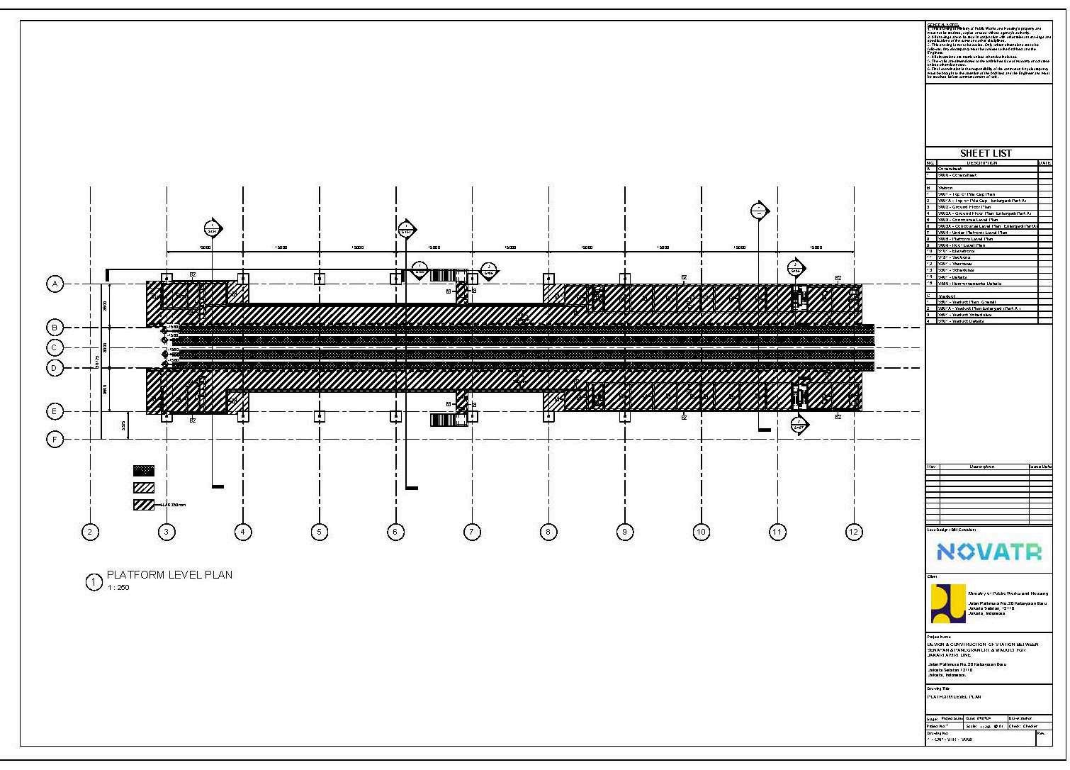
PLATFORM LEVELPLAN

ROOFLEVEL PLAN

ELEVATION VIEW1

ELEVATION VIEW2

ROOF DETAILS

REBAR DETAILS

STAIRCASE DETAILS

PILE&PILE CAPDETAILS


SCHEDULES


KEYLEARNINGS: Creatingschedulesfordifferentstructuralelementsusingscheduletoolinrevit.


FAMILYCREATION:

TRIMBLECONNECT:

FEDERATEDMODEL:

NAVISWORKSSETS:
(STR)-SET01

Revitmodelisexportedtonavisworksandthemodelisdividedintosetsbasedonallthree disciplinesnamelyStructure,Architecture&MEP
6differentsetsarecreatedusingsettoolinnavisworks
(STR)-SET02

(ARC)-SET05

(STR)-SET03

(MEP)-SET06

(STR)-SET04


CLASHDETECTION :

TO1_(STR)-SET02-(STR)Set03

TO1_(STR)-SET01-(STR)Set05
TO1_(STR)-SET01-(STR)Set06


CLASHDETECTIONREPORT

CLASHDETECTIONTOOL


CLASHDETECTED

4DSIMULATION:
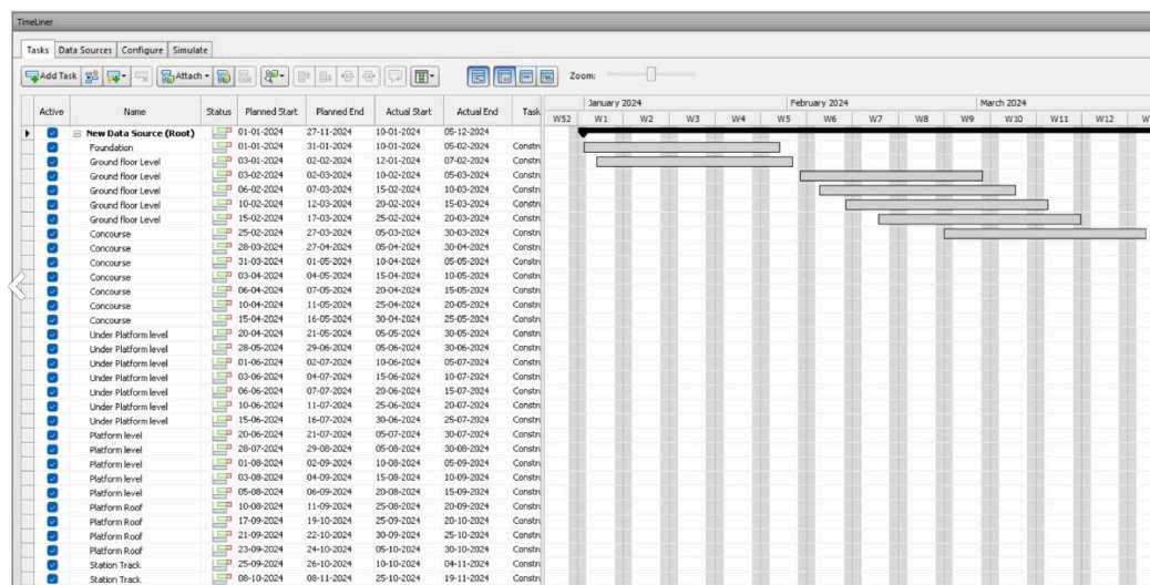
4dProjectparameters:Anewparameteriscreatedforallthestructuralelemntand activityidfromschedulefileisenteredinit.

Timelinertool


Attachingrules

Timeliner: inordertoautoattachthemodel withthescheduledata,anautorulesissetup. byMappingtaskfromcolumnsynchoizationIDto4Dparameterswecreated.
PLANNEDVSACTUALSIMULATION:

PLANNEDSIMULATION: ActualSIMULATION:

KEYLEARNINGS :
Bycomparingtheplannedand actualsimulationthedifferenceintheinterval canbestudiedbasedonwhichfurtherlabourorcostisintroducedintheprojects tocompletetheprojectontime.
Quantificationworkbook:


quantityreportofSTRcolumnexportedtoexcel.


Softwareused:


