
P3.1 At the proportional limit, a 2 in. gage length of a 0.500 in. diameter alloy rod has elongated 0.0035in. and the diameter has been reduced by 0.0003 in. The total tension force on the rod was 5.45 kips. Determine the following properties of the material:
(a) the proportional limit.
(b) the modulus of elasticity.
(c) Poisson’s ratio.
(a) Proportional Limit: The bar cross-sectional area is 222 (0.500 in.)0.196350 in.
and thus, the normal stress corresponding to the 5.45 kip force is
Based on the problem statement, the stress in the bar is equal to the proportional limit; therefore, 43.0 ksi
(b) Modulus of Elasticity: The longitudinal strain in the bar at the proportional limit is long 0.0035 in.
therefore
(c) Poisson’s ratio: The longitudinal strain in the bar was calculated previously as long 0.001750 in./in.
The lateral strain can be determined from the reduction of the diameter:
Ans.
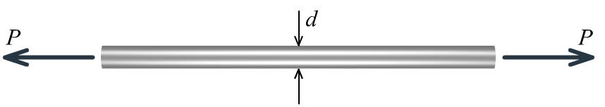
P3.2 A solid circular rod with a diameter of d = 16 mm is shown in Figure P3.2. The rod is made of an aluminum alloy that has an elastic modulus of E = 72 GPa and Poisson’s ratio of = 0.33. When subjected to the axial load P, the diameter of the rod decreases by 0.024 mm. Determine the magnitude of load P
Solution
The lateral strain in the rod is
Using Poisson’s ratio, compute the corresponding longitudinal strain:
Use Hooke’s law to calculate the stress in the rod:
long (72,000 MPa)(4,545.45510 mm/mm)327.273 MPa
The cross-sectional area of the rod is:
(16 mm)201.062 mm
Consequently, the force P that acts on the rod must be 2 (327.273 MPa)(201.062 mm)65,802.086
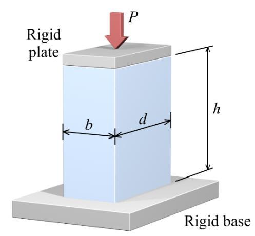
P3.3 The polymer bar shown in Figure P3.3 has a width of b = 50 mm, a depth of d = 100 mm, and a height of h = 270 mm. At a compressive load of P = 135 kN, the bar height contracts by h = –2.50 mm, and the bar depth elongates by d = 0.38 mm. At this load, the stress in the polymer bar is less than its proportional limit. Determine:
(a) the modulus of elasticity.
(b) Poisson’s ratio
(c) the change in the bar width b
(a) Modulus of elasticity: The bar cross-sectional area is
thus, the normal stress corresponding to the 135 kN axial load is
(b) Poisson’s ratio: The lateral strain can be determined from the elongation of the bar depth:
(c) Change in the bar width b: The change in bar width b can be found from the lateral strain:
P3.4 A 0.625 in. thick rectangular alloy bar is subjected to a tensile load P by pins at A and B as shown in Figure P3.4. The width of the bar is w = 2.00 in. Strain gages bonded to the specimen measure the following strains in the longitudinal (x) and transverse (y) directions: x = 1,140 and y = −315

(a) Determine Poisson’s ratio for this specimen.
(b) If the measured strains were produced by an axial load of P = 17.4 kips, what is the modulus of elasticity for this specimen?
(a)
(b) The bar cross-sectional area is
Excerpts from this work may be reproduced by instructors for distribution on a not-for-profit basis for testing or instructional purposes only to students enrolled in courses for which the textbook has been adopted. Any other reproduction or translation of this work beyond that permitted by Sections 107 or 108 of the 1976 United States Copyright Act without the permission of the copyright owner is unlawful.
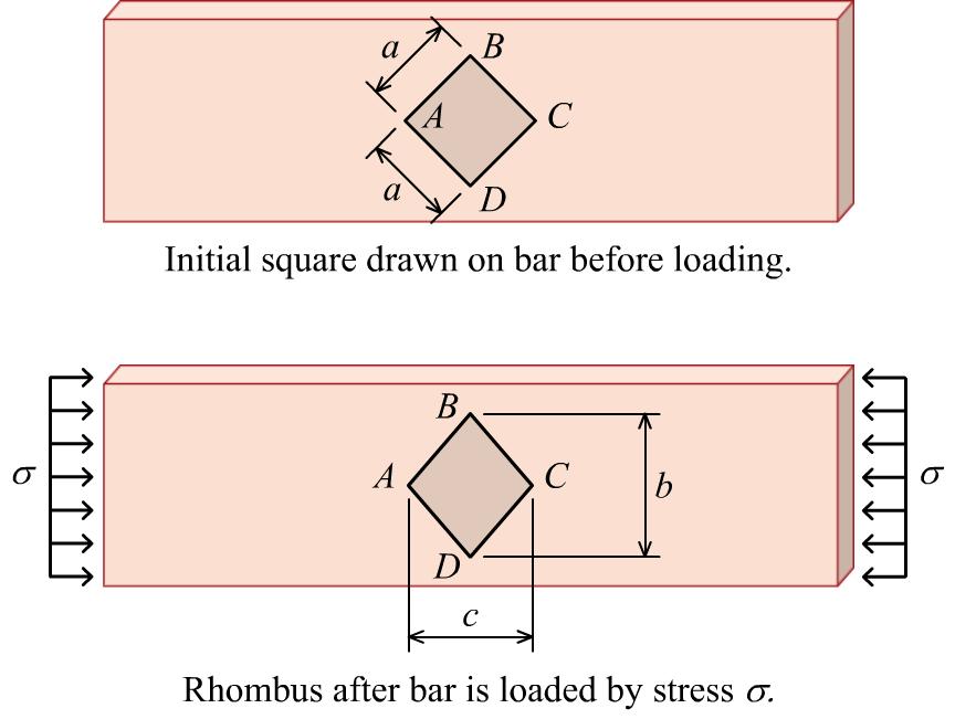
P3.5 A 40 mm by 40 mm square ABCD (i.e., a = 40 mm) is drawn on a rectangular bar prior to loading (see Figure P3.5a). A uniform normal stress of = 54 MPa is then applied to the ends of the rectangular bar, and square ABCD is deformed into the shape of a rhombus, as shown in the Figure P3.5b The dimensions of the rhombus after loading are b = 56.88 mm and c = 55.61 mm. Determine the modulus of elasticity for the material. Assume that the material behaves elastically for the applied stress.
The length of diagonal AC (and also diagonal BD) before deformation is
the normal stress is applied, the longitudinal strain is
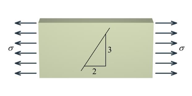
P3.6 A nylon [E = 2,500 MPa; = 0.4] bar is subjected to an axial load that produces a normal stress of . Before the load is applied, a line having a slope of 3:2 (i.e., 1.5) is marked on the bar as shown in Figure P3.6. Determine the slope of the line when = 105 MPa.
Solution
From the given stress and elastic modulus, compute the longitudinal strain in the bar:
long 105 MPa 0.04200 mm/mm 2,500 MPa E
Use Poisson’s ratio to calculate the lateral strain: latlong (0.4)(0.04200 mm/mm)0.01680 mm/mm
Before deformation, the slope of the line is 3 1.500 2 slope
After deformation, the slope of the line is 3(10.01680)2.950 2(10. 1.41 04200)2. 5 084 slope
Ans.
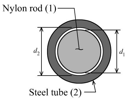
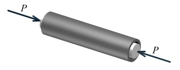
P3.7 A nylon [E = 360 ksi; = 0.4] rod (1) having a diameter of d1 = 2.50 in. is placed inside a steel [E = 29,000 ksi; = 0.29] tube (2) as shown in Figure P3.7. The inside diameter of the steel tube is d2 = 2.52 in. An external load P is applied to the nylon rod, compressing it. At what value of P will the space between the nylon rod and the steel tube be closed?
Solution
To close the space between the nylon rod and the steel tube, the lateral strain of the nylon rod must be: lat 2.52 in.2.50 in. 0.0080 in./in. 2.50 in.
From the given Poisson’s ratio, the longitudinal strain in the nylon rod must be lat long 0.0080 in./in. 0.0200 in./in. 0.4
Use Hooke’s law to calculate the corresponding normal stress: long (360 ksi)(0.0200 in./in.)7.2000 ksi
The cross-sectional area of the nylon rod is 22 (2.50 in.)4.9087 in.
Therefore, the force required to make the nylon rod touch the inner wall of the tube is 2 (7.2000 ksi)(4.9087 in.)35.3429 ki 35.3 kips ( ps
P3.8 A metal specimen with an original diameter of 0.500 in. and a gage length of 2.000 in. is tested in tension until fracture occurs. At the point of fracture, the diameter of the specimen is 0.260 in. and the fractured gage length is 3.08 in. Calculate the ductility in terms of percent elongation and percent reduction in area.
Solution
Percent elongation is simply the longitudinal strain at fracture: (3.08 in.2.000 in.)1.08 in. 0.54 in./in. 2.000 in.2.000 in. percent elonga 54% tion
The initial cross-sectional area of the specimen is 22 0 (0.500 in.)0.196350 in.
The final cross-sectional area at the fracture location is 22 (0.260 in.)0.053093 in.
The percent reduction in area is
percent reduction of area(100%)
Excerpts from this work may be reproduced by instructors for distribution on a not-for-profit basis for testing or instructional purposes only to students enrolled in courses for which the textbook has been adopted. Any other reproduction or translation of this work beyond that permitted by Sections 107 or 108 of the 1976 United States Copyright Act without the permission of the copyright owner is unlawful.
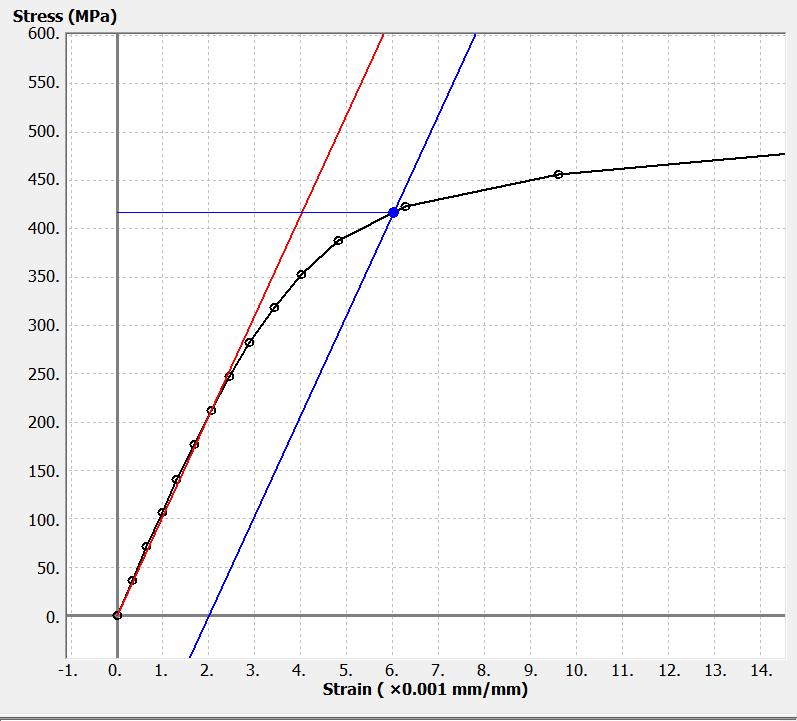
P3.9 A portion of the stress-strain curve for a stainless steel alloy is shown in Figure P3.9. A 350-mm-long bar is loaded in tension until it elongates 2.0 mm and then the load is removed.

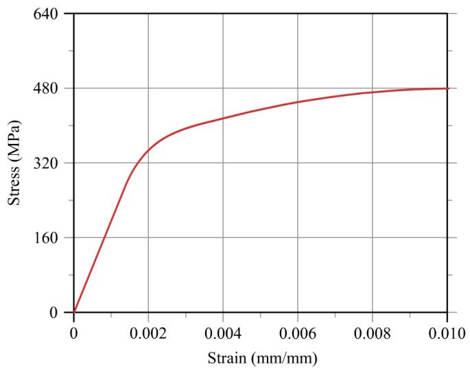
(a) What is the permanent set in the bar?
(b) What is the length of the unloaded bar?
(c) If the bar is reloaded, what will be the proportional limit?
Solution
(a) The normal strain in the specimen is 2.0 mm 0.005714 mm/mm
Construct a line parallel to the elastic modulus line that passes through the data curve at a strain of = 0.005714 mm/mm. The strain value at which this modulus line intersects the strain axis is the permanent set:
permanent set 0.0035 mm/mm Ans.
(b) The length of the unloaded bar is therefore: (0.0035 mm/mm)(350 mm)1.225 mm
350 mm1.225 mm 351.225 mm
(c) From the stress-strain curve, the reload proportional limit is 444 MPa . Ans.
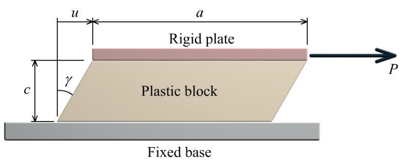
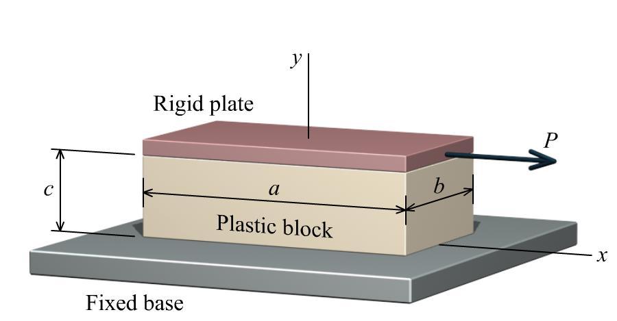
P3.10 A plastic block is bonded to a fixed base and to a horizontal rigid plate as shown in Figure P3.10. The shear modulus of the plastic is G = 45,000 psi, and the block dimensions are a = 4.0 in., b = 2.0 in., and c = 1.50 in. A horizontal force of P = 8,500 lb is applied to the rigid plate. Determine the horizontal deflection of the rigid plate.
Solution
Determine the shear stress from the horizontal force P and the block area (i.e., the area of the y plane surface of the block). To determine the area, visualize the surface that is bonded to the fixed base. This area has dimensions of ab. The average shear stress acting on the block is therefore:
Since the shear modulus G is given, the shear strain can be calculated from Hooke’s law for shear stress and shear strain:
Recall that shear strain is an angle. From the angle and the block thickness c, the horizontal deflection u of the rigid plate can be determined from:
Excerpts from this work may be reproduced by instructors for distribution on a not-for-profit basis for testing or instructional purposes only to students enrolled in courses for which the textbook has been adopted. Any other reproduction or translation of this work beyond that permitted by Sections 107 or 108 of the 1976 United States Copyright Act without the permission of the copyright owner is unlawful.
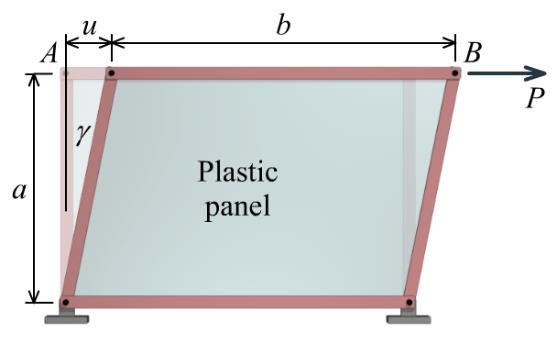
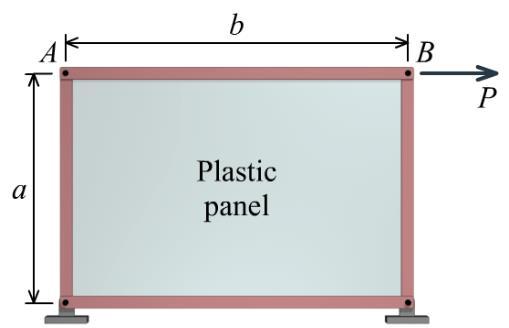
FIGURE P3.10P3.11 A 0.5 in. thick plastic panel is bonded to the pin-jointed steel frame shown in Figure P3.11. Determine the magnitude of the force P that would displace bar AB to the right by 0.8 in. Assume that a = 4.0 ft, b = 6.0 ft, and G = 70,000 psi for the plastic. Neglect the deformation of the steel frame.
Solution
The horizontal displacement of bar AB is u = 0.8 in. This displacement creates a shear strain of
0.8in. tan0.016667
4.0 ft12 in./ft
0.016665 rad
From Hooke’s law, determine the shear stress associated with this shear strain:
70,000 psi0.016665 rad1,166.559 psi
Determine the horizontal force P from the shear area of the plastic panel. This area has dimensions of
1,166.559 psi6 ft12 in./ft0.5 42,000 lb in.
Excerpts from this work may be reproduced by instructors for distribution on a not-for-profit basis for testing or instructional purposes only to students enrolled in courses for which the textbook has been adopted. Any other reproduction or translation of this work beyond that permitted by Sections 107 or 108 of the 1976 United States Copyright Act without the permission of the copyright owner is unlawful.
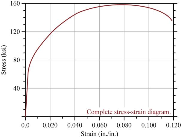
FIGURE P3.11P3.12 The complete stress–strain diagram for a particular stainless steel alloy is shown in Figure P3.12a/13a This diagram has been enlarged in Figure P3.12b/13b to show in more detail the linear portion of the stress-strain diagram. A rod made from this material is initially 800 mm long at a temperature of 20°C. After a tension force is applied to the rod and the temperature is increased by 200°C, the length of the rod is 804 mm. Determine the stress in the rod, and state whether the elongation in the rod is elastic or inelastic. Assume the coefficient of thermal expansion for this material is 18×10−6/°C.
Solution
The 4 mm total elongation of the rod is due to a combination of load and temperature increase. The 200°C temperature increase causes a normal strain of: 6 (1810/)(200)0.003600 mm/mm
which means that the rod elongates (0.003600 mm/mm)(800 mm)2.8800 mm
The portion of the 4 mm total elongation due to load is therefore 4 mm2.8800 mm1.1200 mm
The strain corresponding to this elongation is 1.1200 mm 0.001400 mm/mm 800 mm
By inspection of the stress-strain curve, this strain is clearly in the linear region. Therefore, the rod is elastic in this instance.
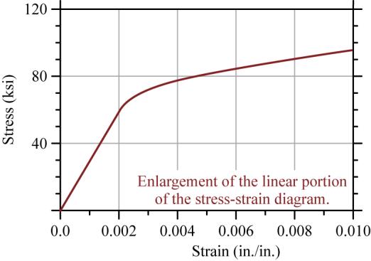
For the linear region, the elastic modulus can be determined from the lower scale plot: (400 MPa0) 200,000 MPa (0.002 mm/mm0)
Using Hooke’s law (or directly from the –diagram), the stress corresponding to the 0.001400 mm/mm strain is (200,000 MPa)(0.001400 mm/mm 280 MP ) a
Ans.
P3.13 A tensile test specimen of stainless steel alloy having a diameter of 12.6 mm and a gage length of 50 mm was tested to fracture. The complete stress–strain diagram for this specimen is shown in Figure P3.12a/13a. This diagram has been enlarged in Figure P3.12b/13b to show in more detail the linear portion of the stress-strain diagram. Determine:
(a) the modulus of elasticity.
(b) the proportional limit.
(c) the ultimate strength.
(d) the yield strength (0.20% offset).
(e) the fracture stress.
(f) the true fracture stress if the final diameter of the specimen at the location of the fracture was 8.89 mm.
Solution
From the stress-strain curve, the proportional limit will be taken as = 60 ksi at a strain of = 0.002. (Obviously, there can be quite a bit of leeway in pulling numbers from such a limited plot.)
(a) The modulus of elasticity is 60 ksi 0.002 in./in. 30,000 ksi
Ans.
(b) From the diagram, the proportional limit is taken as 60 ksi PL Ans.
(c) The ultimate strength is 159 ksi U Ans.
(d) The yield strength is 80 ksi Y Ans.
(e) The fracture stress is fracture 135 ksi Ans.
(f) The original cross-sectional area of the specimen is 22 0 (0.495 in.)0.192442 in. 4 A
The cross-sectional area of the specimen at the fracture location is
Excerpts from this work may be reproduced by instructors for distribution on a not-for-profit basis for testing or instructional purposes only to students enrolled in courses for which the textbook has been adopted. Any other reproduction or translation of this work beyond that permitted by Sections 107 or 108 of the 1976 United States Copyright Act without the permission of the copyright owner is unlawful.
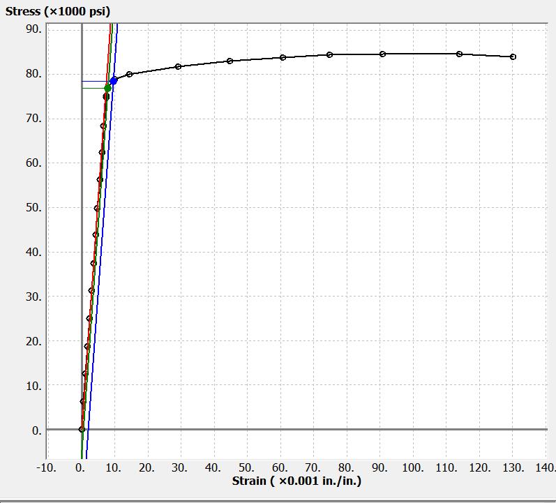
FIGURE P3.12a/13a FIGURE P3.12b/13bP3.14 A 7075-T651 aluminum alloy specimen with a diameter of 0.500 in. and a 2.0-in. gage length was tested to fracture. Load and deformation data obtained during the test are given. Determine:
(a) the modulus of elasticity.
(b) the proportional limit.
(c) the yield strength (0.20% offset).
(d) the ultimate strength.
(e) the fracture stress.
(f) the true fracture stress if the final diameter of the specimen at the location of the fracture was 0.387 in.
Solution
The plot of the stress-strain data is shown below.
The same plot is shown below, enlarged to better show the linear portion of the stress-strain curve. The initial cross-sectional area of the specimen is
(a) Using the data point for the 9,783 lb load and 0.0096 in. elongation, the modulus of elasticity can be calculated as
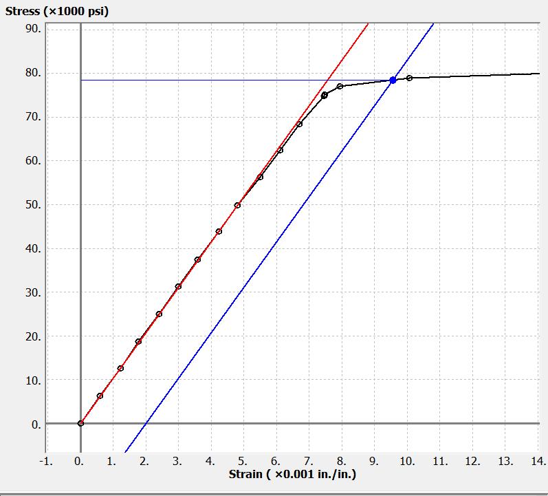
9,783 lb 49,824.3 psi 0.19635 in.
(b) Using the data point for the 9,783 lb load and 0.0096 in. elongation, the proportional limit is calculated as
psi
(c) The yield strength by the 0.20% offset method is
psi
(d) The ultimate strength is
(e) The fracture stress is
(f) The cross-sectional area of the specimen at the fracture location is
0.387 in.0.11763 in.
true fracture stress is therefore
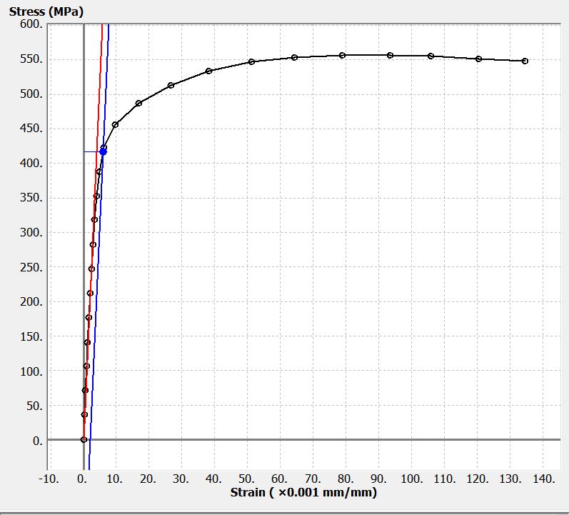
P3.15 A Grade 2 Titanium tension test specimen has a diameter of 12.60 mm and a gage length of 50 mm. In a test to fracture, the stress and strain data below were obtained.
Determine:
(a) the modulus of elasticity.
(b) the proportional limit.
(c) the yield strength (0.20% offset).
(d) the ultimate strength.
(e) the fracture stress.
(f) the true fracture stress if the final diameter of the specimen at the location of the fracture was 9.77 mm.
Solution
The plot of the stress-strain data is shown below.
The same plot is shown below, enlarged to better show the linear portion of the stress-strain curve. The initial cross-sectional area of the specimen is
(a) Using the data point for the 30.84 kN load and 0.123 mm elongation, the modulus of elasticity can be calculated as
MPa
mm/mm
(b) From the diagram, the proportional limit is taken as 247 MPa
(c) The yield strength by the 0.20% offset method is 417 MPa
(d) The ultimate strength is
(e)
(f) The cross-sectional area of the specimen at the fracture location is