SIX WAYS TO IMPROVE THE SUSTAINABILITY OF MARITIME HVAC SYSTEMS INSUSTAINABILITYHVACDESIGNHEINENHOPMAN.COM
Having a
andgoodasavoidedwarmingwhereenvironmentcleanerglobalisasmuchpossiblewillbeforhumansanimalsalike.
When it comes to sustainability our most obvious focus is on measures designed to keep energy use as low as possible. But that’s only half the story because there are various other areas in which we contribute to an eco-friendlier sector.
INTRO Everyone agrees about the benefits of sustainability. Having a cleaner environment where global warming is avoided as much as possible will be good for humans and animals alike. Reducing energy consumption has a favourable economic effect too. So how does Heinen & Hopman contribute to a more sustainable way of doingReducingbusiness? consumptionenergyhas a favourable economic effect too.
3


4 CHAPTERSIntro 3 Chapters 4 Summary 5 Part 1 – Sustainability is more than a system that saves energy 6 Part 2 – Refrigerants 7 Part 3 – Smart design of HVAC spaces 10 Part 4 – Waste heat recovery 13 Part 5 – Electric efficiency 18 Part 6 – Return air recovery 21 Part 7 – Energy management 24 Conclusion 27
5 PART 1 SUSTAINABILITY IS MORE THAN A SYSTEM THAT SAVES ENERGY

6
EMMISSIONS
When we talk about sustainability in the maritime world, we’re primarily talking about reducing CO2 emissions. This is achieved by limiting consumption of the fuel used for two main purposes on a ship: 1. To provide energy via the generators 2. To propel the ship by means of the engines
The HVAC installation is one of the systems that weighs heavily on the e-load. The use of energysaving components and an efficient system helps ensure a low e-load balance, resulting in smaller generators and less fuel consumption. Another issue is weight savings. Clever design and material choice lead to enormous reductions in weight, resulting in a lighter vessel and lower fuel
REDUCINGconsumption.CO2 PART 1 SUSTAINABILITY IS MORE THAN A SYSTEM THAT SAVES ENERGY
• Smart design • Waste heat recovery
•
PRODUCT UNLEASHINGLIFECYCLEINNOVATION
With these three main points in mind, we have created a whitepaper that zooms in on the possibilities of making HVAC systems more sustainable. Each part will deal with a key theme and discuss the associated solutions related to:
• Refrigerants
• Electric efficiency Energy recovery Energy management. SUSTAINABLE STORY
•
A
Then there is the matter of innovation. The solutions proposed now provide a hefty degree of energy reduction, but we are aiming higher and higher via new techniques and products. These involve innovative ways of engineering and, of course, the integration of alternative fuels. While diesel remains the major fuel used in the maritime sector currently, LNGs are increasingly emerging along with electric motors and experiments with hydrogen. Such developments require smart adjustments and new forms of energy efficiency. Sustainable thinking looks beyond CO2 reductions to the entire product cycle. Which materials do we use for an installation? How are they manufactured and how much energy consumption is involved? What is the lifespan of the material and the components? How are we going to recycle them at the end of their lifetime? These are all matters to consider in the process.
7 PART 2 REFRIGERANTS

2
FULL CIRCLE Today there are more and more onshore installations running on natural refrigerants, with the maritime sector lagging somewhat behind. Vessels launched before 2000 run on R-22 and the newer ones on R134a and R404a for air conditioning and provision cooling respectively. And not without reason...
A refrigerant loss in the range of 20 to 40% is reported annually in the maritime sector as ships are permanently buffeted by the continuous motion of wind and waves. The resulting damage and leaks causes refrigerant losses equivalent to 18.2 million tonnes of CO2, more than the annual emissions of a country like Croatia.
American company Dupont was the first to come up with a refrigerant that did not have these negative properties, released under the brand name Freon R-12. These synthetic refrigerants were increasingly refined over the years, until we realised they were helping to destroy the ozone layer and fill our atmosphere with greenhouse gases. Now we’re returning to natural refrigerants which, ironically, are the ones replaced a century ago because they were considered toxic and dangerous.
PART REFRIGERANTS
The first cooling machines were introduced in the early 20th century and ran on refrigerants such as ammonia, CO2 and sulphur dioxide. Due to concerns about safety, toxicity, corrosion and high pressure, alternatives were sought that would cause less damage when leaks occurred.
THE ONBOARD SITUATION
The perfect refrigerant does not affect the ozone layer and has a GWP of around 1 (GWP stands for Global Warming Potential and indicates the equivalent impact of CO2). But that’s not all: the refrigerant should ideally be non-corrosive, non-flammable and non-toxic. Also, we have to consider the refrigerant’s boiling point, which must be just slightly below the desired cooling temperature. While you can of course play with this by changing the pressure, it’s best to avoid extremely high pressures – these are more dangerous and require stronger and more expensive materials. The specific heat of the refrigerant must be taken into account too. That is the amount of energy it draws from the environment during evaporation.
THE PERFECT REFRIGERANT
8
The disadvantages of natural refrigerants such as high pressure (CO2), toxicity (ammonia) and flammability (propane) can cause major difficulties with the leakage losses on ships and in the built-in technical rooms where cooling machines are located.
CONCLUSION
The downside of natural refrigerants is their toxicity and flammability, with agencies such as DNV and Lloyds each having their own rules for the use of highly flammable substances. Despite this, progress is being made in the maritime sector. There are increasingly better synthetic refrigerants with only a fraction of the GWP value of commonly used refrigerants such as R134a and R404a.
Cooling installations on land are increasingly switching to natural refrigerants with a low GWP value. Cooling needs on ships are very different due to their continuous movement and more frequent leaks.
Nonetheless, there’s a big difference between the GWP value of one synthetic refrigerant (R134a – GWP 1430) and the other (R515B – GWP 293). And although not perfect, these alternative refrigerants are a big step in the right direction and increasingly used.
THE RIGHT DIRECTION
The search for the perfect refrigerant is a tough one, then, as there’s always something wrong.
For example, a low GWP refrigerant such as R-1234ZE is registered as lower flammable (A2L) and cannot be used. In addition, ships have to deal with class bureaus that have yet to set regulations for these refrigerants so don’t accept them onboard.
9
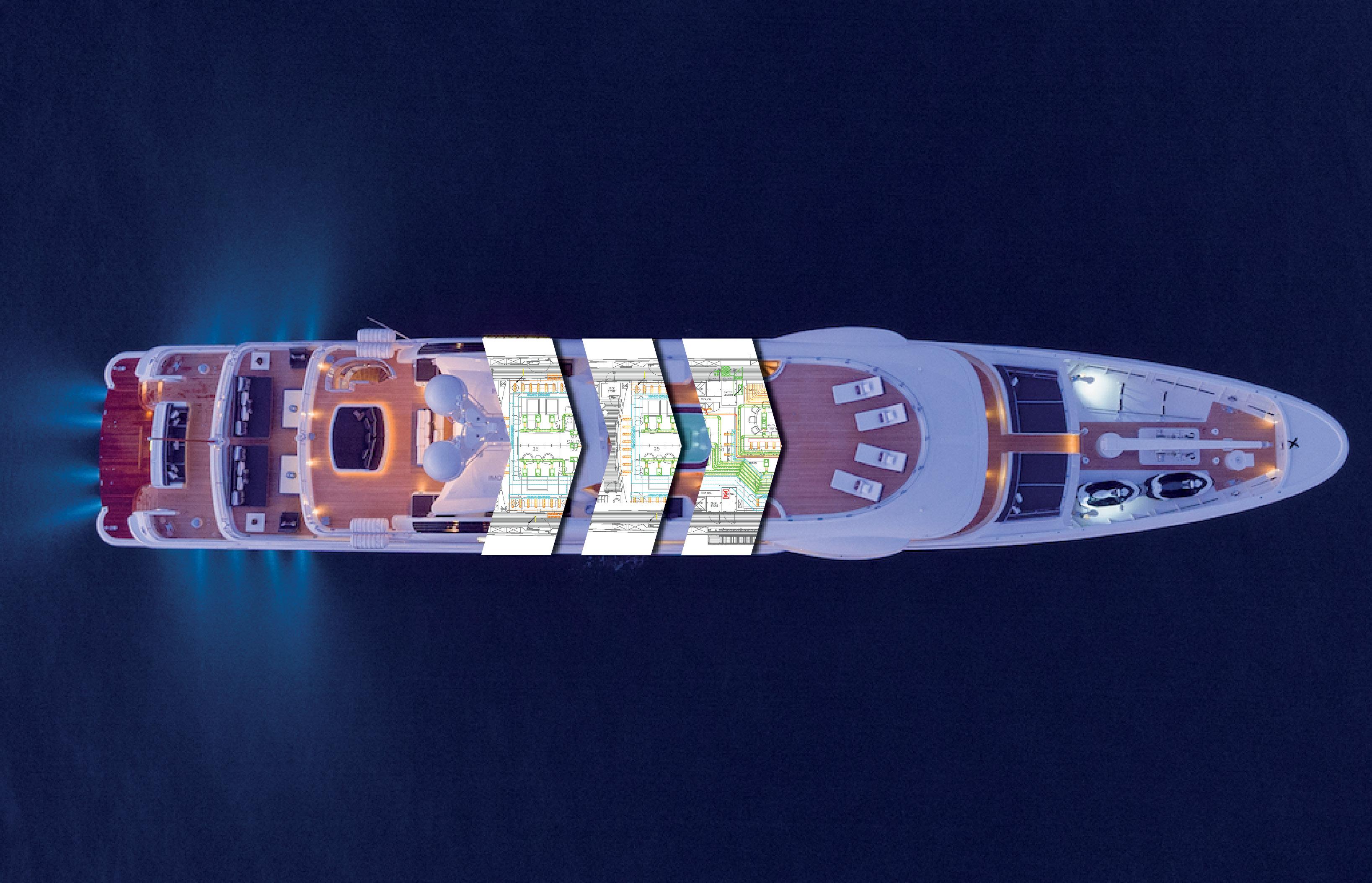
10 PART 3 SMART DESIGN OF HVAC SPACES
The energy efficiency of two HVAC designs can be widely different even when their conditions and air amounts are the same. How is this possible? By smart design of the AC zones and the tactical placement of technical spaces with the air-handlers and vertical duct shafts in the centre of a zone.
There is a correlation between amount of air in an HVAC system and the volume of the AC room where the air handling unit is placed. Dividing the ship into different AC zones as efficiently as possible creates the perfect air volume/technical space volume ratio. But that’s not all: placing the AC room in the right position leads to a multitude of benefits that greatly improve the overall sustainability of the HVAC system.
SAVE ON WEIGHT
3
PART SMART DESIGN OF HVAC SPACES
11
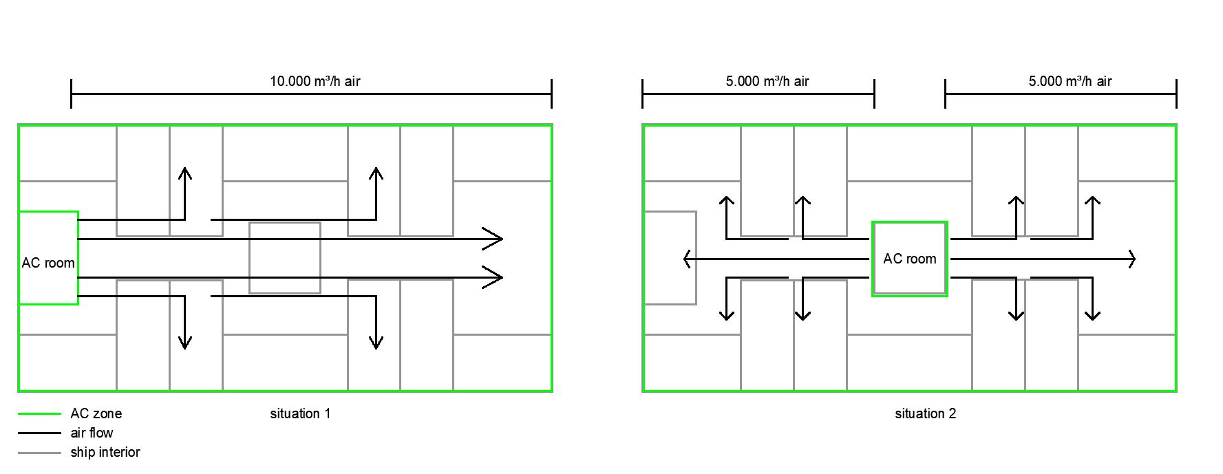
Let’s say that the overall amount of air for an area is 10,000 m³/h. In one situation the technical space is placed on the boundary of the AC zone. All the ducts come from the same side, resulting in bigger duct dimensions and bulkhead penetrations. In the other situation, the technical space is positioned more tactically in the centre of the AC zone.
This is an oversimplified example in order to give you an idea. In practice there are more factors to consider, such as the ship’s structure and fire and watertight zones.
Image 1: example of smart design More air means more and bigger ducts, which translates into a higher weight. The amount of air needed to meet the specified conditions is determined by transmission calculations and cannot therefore be changed. Using smart design, on the other hand, allows for significant reductions in the amount of ducting.
REDUCTION OF VALVES
12
Another benefit of the smart division of AC zones is the option to save energy when a zone is not in use. For example, you can build energy-saving options into the software for when certain zones like crew, guest or owner areas are unoccupied. Re-heaters can be switched off or set to operate when relative humidity exceeds a certain set point, and you can have central temperature control on recirculation air. From a financial point of view, the advantages are obvious. Fewer ducts and valves and a shorter installation time saves you both energy and money.
Bringing air from one part of the ship (AC room) to a cabin thirty metres further costs energy, especially when it is meandering through a complex duct system. The resistance of a duct system with all its bends and flaps is overcome by the head pressure of the fan. A higher head pressure obviously results in more power consumption.
An HVAC system contains a range of different valves such as watertight valves, fire dampers, closing valves and smoke dampers. Each valve has a weight, creates air resistance and uses electricity, with most also needing a penetration. It is best then to keep the number of valves in the system to a minimum. Smart design of AC zones contributes to a reduction in unnecessary valves. This requires a clear overview of the fire zones in a ship and the positioning of watertight bulkheads. Not that they shouldn’t be trespassed, sometimes this is unavoidable, but dividing the AC zone so that it fits inside a fire zone or watertight area can save a lot of valves.
REDUCED ENERGY CONSUMPTION
CONCLUSION
As well as saving on weight, cutting the duct system in half by smart design reduces energy consumption as the smaller fans used do not need such a high head pressure. We should also consider that the resistance depends on the air speed and will increase quadratically at higher speeds.
Much of this might seem quite obvious and indeed it is but the reality can be quite a puzzle. Our advice is to start thinking about AC zones as early as possible in the pre-engineering phase.
13 PART 4 WASTE HEAT RECOVERY

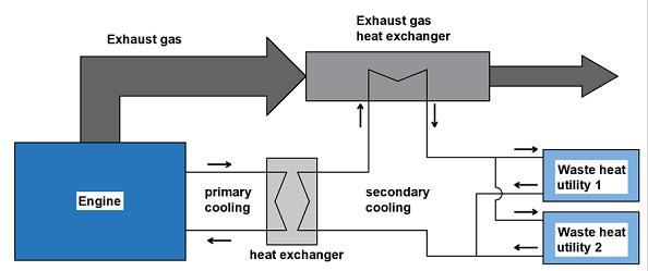
Using a secondary system with heat exchangers and water as an energy carrier, heat from the engine cooling system and/ or the exhaust gasses can be extracted and used for other purposes. Think of hot water boilers, HVAC heaters and absorption cooling.
PART 4 WASTE HEAT RECOVERY
14
Most maritime diesel engines have an efficiency of only 50%, with the remaining energy released from fuel combustion being lost to the atmosphere in the form of heat. Add to that the heat dissipated by the engine and generator cooling systems and you have a large amount of free thermal energy available. It is obviously a shame to let this go to waste but how can you most effectively use it to your advantage?
One of the most obvious ways to reduce our ecological footprint is to recover the heat that has already been generated by other activities. The thermal energy stored inside this heat can be used to fuel other processes, making double use of a single power source. Besides heat, also cold can be recovered and reused.
Image 2: Simplified diagram of how to extract waste heat
A good purpose for residual heat is the hot water used for sanitary utilities such as showers, baths and sinks. With a heat exchanger, thermal energy is redirected from engines/generator cooling and exhaust fumes. Water is heated and stored in massive boilers of up to 1000 litres. BOILER HEATING
Image 3: Simplified diagram of waste heat recovery for hot water heating Backup is provided by separate electric boilers or an electric flow heater, although this is only used in exceptional situations such as when the vessel is on shore power. Residual heat fully covers the heat demand most of the time.
15
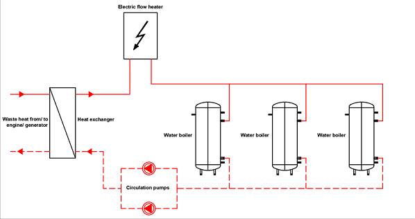
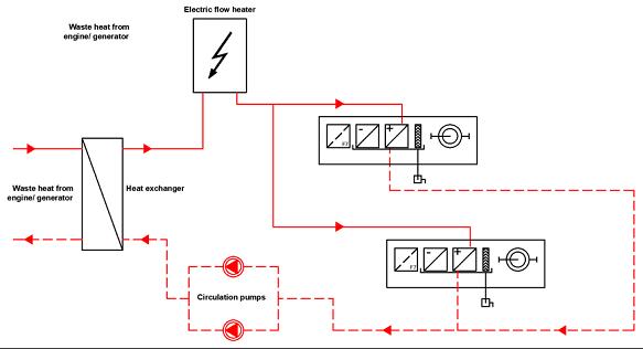
Image 4: Simplified diagram of waste heat recovery for HVAC heating
16
A significant amount of energy is needed to warm up cooled air inside the air handling units and therefore this is an ideal purpose for a waste heat recovery system. In this system water is used as an energy carrier with the heating coils in the air handling unit serving as a water-fed air heater. A combination of heat exchangers and electrical circulation pumps extracts the thermal energy from exhaust gases and the engine/generator cooling system.
HVAC HEATING
Up to 100% of the heat demand is covered by the residual heat from the generators and engines, both pre-heating and re-heating. As a backup, electric flow heaters have been added to the system that step in on the rare occasions when the generator is not running.
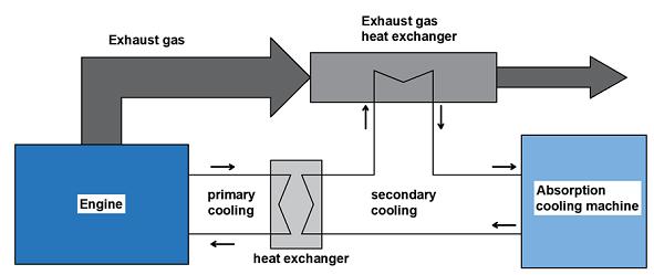
ABSORPTION COOLING
Image 5: Simplified diagram of waste heat recovery for absorption cooling While absorption cooling machines have very high efficiencies, they can only be used when waste heat is available. Absorption chillers are therefore only used as an extra cooling measure in addition to conventional cooling machines. Another way of energy-efficient cooling is found on LNG-powered vessels. Liquid Natural Gas is stored on the vessel in tanks where the temperatures are -160°C. The liquid fuel must change phase to gas and is therefore heated before entering the ship’s engine. Some of this cold can be recovered and used for chilled water systems, provision cooling and freezers. Here we speak of waste cold recovery. Just as is the case with absorption cooling, the capacity is only available as long as the engine is running. Energy consumption is high onboard vessels, especially commercial vessels like RoPax and cruise vessels. One of the highest energy consumers on these vessels is the HVAC system. Waste heat recovery is an excellent measure to improve energy efficiency. The thermal energy is used to warm up the boilers for hot water plus the pre-heating and re-heating in air handling units. Although extra heat exchangers and circulation pumps are needed, the complete heat demand is covered in most of the cases. Waste heat can also be used to power up an absorption cooling machine, providing chilled water.
The essence of an absorption cooling machine is to use (waste) heat to create cold. An absorption cooling machine does not have a compressor – the component responsible for the biggest part of energy consumption in a regular cooling machine. Instead, it uses heat recovered in the same way as the hot water and HVAC heating to power up the process.
17
CONCLUSION
18 PART 5 ELECTRIC EFFICIENCY5
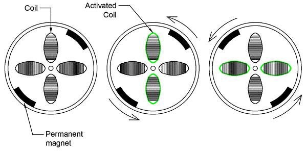
Like conventional electric motors, brushless motors use magnets and a magnetic field. A current that runs through one of the coils activates a magnetic field and attracts the (permanent) magnets – which are fixed on the rotating part – to start moving. Like a carrot on a stick, the current jumps over to the next coil so the magnets keep going after it.
An HVAC system is nothing more than a number of physical processes being driven by various main components. The use of these drive components is responsible for 75% to 95% of the HVAC’s total electricity consumption. Considerable savings can be enjoyed by making use of efficient solutions such as: • Brushless DC motors • Magnetic bearing compressors.
19 PART 5
The position of the rotor and the speed at which the coils are activated is determined by a controller, which is often equipped with a microprocessor. This allows the motor to rotate at variable speeds/flows and replaces the use of a frequency inverter. Unfortunately, the maximum power provided by a brushless DC motor is limited and the threshold for ECMs lies at around 4 kW. When converting electricity into mechanical power in this range, the brushless motor is more efficient than a conventional electro motor with electric efficiencies of around the 92% mark compared to the 80%-85% of conventional three-phase motors.
BRUSHLESS DC MOTOR Image 6: Principle of a brushless DC motor
ELECTRIC EFFICIENCY Electricity is what drives an HVAC system. Compressors, fans, circulation pumps… Everything that moves is electrically driven. It’s not hard to imagine how much energy consumption can be reduced if those electromotors are replaced by more efficient ones.
Brushless DC electro motors – also known as electronically commutated motors (ECMs) –have many advantages. They require no maintenance, have instantaneous speed control and are low on noise levels. Unlike their brushed counterpart, ECMs do not require electrical conducts (brushes) that slide against the shaft as it rotates. This brushing normally results in friction and sparks, which is why ECMs are ideal for use in potentially explosive environments.
5
Choosing a magnetic compressor eliminates the friction problem. This type of compressor has its shaft hanging in a magnetic field. The magnetic bearings allow the compressor to operate without the use of oil for lubrication, reducing any energy losses due to friction. The absence of oil has another advantage which is that the heat transfer efficiency is much higher without a film layer of oil in the evaporator and condenser.
FINAL THOUGHTS
Conventional compressor electromotors of the same size have efficiencies of around 92%. Magnetic compressors reach electric efficiencies up to 97%. The advantage of a magnetic compressor is that it delivers the same cooling capacity with a lower electrical power as it does not suffer from frictional resistance.
Mechanical parts involved in the process rub and twist against each other and oil is used as a lubricant in order to keep those losses to a minimum.
One of the systems that weighs heavily on the e-load are the chillers and provision cooling plants.
Drive components – the electromotor which converts electricity into mechanical energy and powers all physical processes in the HVAC installation – consume the most energy. Electricity is not evenly transferred into mechanical energy due to heat and friction. Efficient solutions like the brushless motor and magnetic compressor have a higher transfer rate because they mainly reduce the friction.
Electro motor efficiency improvements from 85% to 92% (fans/pumps) or 92% to 97% (compressors) may look like marginal gains, but on top of other sustainable measures, the total savings will be significant. Moreover, these solutions offer other improvements in addition to e-motor efficiency such as an absence of oil, low maintenance costs and reduced noise levels.
MAGNETIC BEARING COMPRESSORS
20
The main electric energy consumer is the compressor that basically sets the whole cooling cycle in motion. There are many different types of compressors, ranging from screw to piston and scroll. The problem with conventional compressors is that a lot of energy is lost due to friction.
21 PART 6 RETURN AIR RECOVERY6
• Recirculation
• Crossflow heat exchange
This method involves having a crossflow heat exchanger built inside the air handling unit. Before leaving the ship, return air runs through this heat exchanger which directs the conditioned air flow crosswise along the incoming air flow, separated by a thin ribbed metal plate. Heat transfer takes place through conduction to the incoming air stream. The efficiency of a crossflow heat exchanger is around 50%.
CROSSFLOW HEAT EXCHANGER
One of the simplest ways of return air energy recovery is via recirculation. The air handling unit provides the vessel (or a section thereof) with the amount of treated air necessary for a comfortable and healthy environment. Part of this air volume is recirculated and the amounts of fresh air are based on the recirculation rate. A common ratio is 50/50, which indicates that 50% of the total air is recirculated while the other half is fresh. Even better results are gained with a 60/40 rate.
PART 6 RETURN AIR RECOVERY
TWIN-COIL
RECIRCULATION
• Twin-coil system
• Heat recovery wheel
22
Now it’s time to look at other ways of recovering energy. One of the most applied forms of energy recovery in HVAC systems is return air. There are multiple methods as we will see… But which is most suitable for your Thesystem?outside air brought in from an HVAC air handling unit is used for two main purposes: to create an indoor environment according to the specified conditions and to provide sufficient fresh air. The latter is a necessity as it prevents headaches and reduces the risk of infection and the spread of disease. In short, fresh air keeps the passengers and crew healthy and comfortable. Before entering the cabins and rooms, outside air needs to be treated in the air handling unit and brought to the right condition. A lot of energy is used in this procedure and failing to reuse some of this energy is clearly a waste. Energy recovery from return air can be done in four main ways:
6
A twin-coil system consists of two water-fed elements called the cooler and economizer, located in the supply and discharge duct respectively. A built-in circulation pump transports the energy recovery medium taking heat from the economiser and transports it to the cooler. The efficiency of this system is also around 50%. SYSTEM
23
In the examples above we assume a summer situation where the incoming air is warm and therefore needs to be cooled. Naturally, all energy recovery methods also work in winter where the incoming air is colder and needs to be heated.
Furthermore, the methods mentioned are all applicable to full air systems where the central air handling unit provides air for both the conditioning of the cabins and ventilation purposes. This requires high air volumes and, therefore, bigger ducting systems. Vessels with limited space can be equipped with a local cooling installation like a fan coil system. A central air handling unit only provides the fresh outside air. According to ISO 7547, a minimum of 0.008 m³/s per person of fresh outdoor air is required. Because the unit only provides fresh air, the ducting system will be a lot smaller compared to a full air system.
In this installation, all air (except the necessary fresh air) is recirculated. The conditioning of the cabin or room is done locally by a fan coil unit for example, which treat the recirculated air. Still, energy recovery systems like a crossflow heat exchanger, twin-coil and heat recovery wheel can be applied on the exhaust air from toilets and sanitary spaces to make it even more sustainable. THOUGHTS
FINAL
HEAT RECOVERY WHEEL
With a level of 70%, the highest efficiency rates are realised with a heat recovery wheel. This method brings incoming and outgoing air flows together in a wheel. The air currents enter the wheel in opposite directions, with both the warm and cold air filling half of the rotary heat exchanger. As the wheel rotates at a slow rate, the energy can be given off to the duct wall for half a revolution. The subsequent half revolution allows the duct wall to relinquish its energy to the incoming air stream.
24 PART 7 ENERGY MANAGEMENT7
Think of lower fan speeds and adjusted temperatures – i.e., all the parameters that contribute to an eco-friendlier setting. Eco mode is especially welcome on larger vessels such as superyachts and cruise ships which have a multitude of cabins and areas. All or a select group can be switched to a less energy consuming setting with a single swipe/click.
7
Today, most houses have a smart thermostat that can be programmed for every separate day, and which displays the actual energy consumption. Your very own little energy management system. The same goes for operating the HVAC system on your vessel: whereas every cabin used to be set manually, nowadays everything is controlled centrally via iPad and other smart Alldevices.ofthis results in lower energy costs. Below we discuss some of the features that an energy management system is capable of.
It’s not that long ago when houses had central heating systems equipped with a single analogue thermostat, placed in the living room. Temperatures had to be set manually and only one space (the living room) was leading.
25
PART 7
Most of the variety of measures that can be taken in relation to sustainability rely on hardware. One topic that we have yet to explore is the software side. Energy management through operating systems such as SCADA not only gives an insight into energy consumption – it is also capable of reducing the total energy use of your HVAC system.
EVOLUTION OF CONTROLLING SYSTEMS ENERGY
MANAGEMENT
A number of spaces and areas on vessels are filled with lots of people at given times such as restaurants on a cruise ship, recreation spaces on a ferry and mess halls. These rooms are often so large that they have their own air handling unit. Large crowds need serious amounts of fresh air, the conditioning of which costs energy. As they are only temporarily occupied with people, integrating a CO2 detection system within these spaces helps ensure a more efficient use of fresh air. The more people are gathered in a space, the higher the CO2 amount will be and the greater the volume of fresh air required. The signal is redirected to a system of valves which control the balance between fresh and recirculated air. This prevents unnecessary energy consumption in relation to fresh air generation.
CO 2 SENSORS
Whether it is known as night mode, hotel mode or harbour mode, the same principle applies. A selected group of cabins and/or spaces are switched to a setting which consumes less energy.
ECO MODE
INSIGHT IN ENERGY CONSUMPTION
INTELLIGENT VAV
FINAL THOUGHTS
HVAC systems use conditioned air and cooling installations have chilled water flowing through the pipes. Energy management and operating systems run on a constant flow of information in the form of ones and zeroes that are streaming through fibre cables at enormous velocities. The future is data driven. The more data available, the more accurate the system’s operation. Sensors, cables and communication equipment therefore need to be accurately set up for the best results. That said, the interventions with an energy management system do not have to be extremely large to function optimally. Wireless connections and the internet of things offer more and more options.
This is a new kind of technology that detects when people are in a room and moves the conditioned air to that area. Using precision targeting, the system pinpoints and follows the people so that they walk in their own bubble of comfort.
26
Real-time feedback on energy consumption of the HVAC system depends entirely on how sophisticated the operating system is. There are a lot of possibilities such as the energy use of different components and having data logged into a SQL database and analysed for anomalies.
Energy savings which lead to lower fuel consumption and reduced CO2 emissions are the current focus. This leaves a far smaller ecological footprint while the low fuel use also saves a lot of money.
The HVAC system is the second largest consumer of energy after propulsion. The challenge is monitoring and reducing the energy consumption of HVAC to make ships more and more efficient.
27 CONCLUSION
Achieving an energy-saving system requires innovation. By constantly raising the bar for ourselves, we will ensure that our customers reap the maximum rewards.
www.heinenhopman.com Heinen & solutionssustainableencouragesHopmanamoreworld.Byprovidingeco-friendlyandservicesweofferourclientstheoptionofreducingenergyconsumptionandthusCO2emissions. Ventilation Air Conditioning RefrigerationHeating PROVIDED BY HEINEN & HOPMANInside22º C OUTSIDE35C45°C HUMIDITY90%40% Do you require more information about energy-saving HVAC or do you require a custommade solution? I am keen to help you -Ericfurther!StoffelsenSalesManagersales@heinenhopman.com Austria T: +43 1720 1309 E: info@drewsmarine.com Brazil T: +55 213 587 4241/4244 E: info@br.heinenhopman.com Canada T:+1 450 659 6571 E: info@bronswerkgroup.com Denmark T: +45 5164 1614 E: admin@teknotherm.no France - La Ciotat T: +33 4 4204 8685 E: info@heinenhopmanfrance.com France - Antibes T: +33 4 8902 4562 E: info@heinenhopmanfrance.com Germany T:+49 4073 1680 E: info@drewsmarine.com Germany T:+49 471 9869 300 E: info@moehringms.com India T: +91 336 499 1293 E: info@heinenhopmanindia.com Italy T: +39 187 187 8500 E: info@it.heinenhopman.com The Netherlands (HQ) T: +31 33 299 2500 E: info@heinenhopman.com The Netherlands - Rotterdam T: +31 18 020 9210 E: binnenvaart@heinenhopman.nl Norway T: +47 6919 0900 E: admin@teknotherm.no Peoples Republic of China T: +86 213 253 2896 E: info@cn.heinenhopman.com Poland T: +48 914 331 800 E: admin@teknotherm.no Romania T: +40 236 448 222 E: office@ro.heinenhopman.com Russia T: +7 812 449 3535 E: info@heinenhopman.ru Singapore T: +65 6897 7879 E: info@sg.heinenhopman.com South Korea T: +82 704 901 0000 E: info@kr.heinenhopman.com Spain T: +34 932 259 668 E: info@es.heinenhopman.com Sweden T: +46 3121 7500 E: admin@teknotherm.no Turkey T: +90 216 493 8118 E: info@tr.heinenhopman.com UAE - Abu Dhabi T:+971 2550 4147 E: info@caspuae.com UAE - Dubai T: +971 45840111 E: info@caspuae.com USA - Seattle, Washington T: +1 206 632 7883 E: sales.uk@teknotherm.com USA - Fort Lauderdale, Florida T: +1 954 463 0110 E: info@arwmaritime.com USA - Houma, Louisiana T: +1 985 876 7982 E: leblanc@leblancandassociates.com “ “