MODEL L^' 1
BOOK No. * 02 A
SERIAL No.
MACHINE SERIAL NUMBER
Themachine serialnumber isontheserialnumber capacity plate,or ontheCrane Rating Manual located inside the operator's cab. The serial number should always be furnished when ordering parts for the machine or when corresponding with the distributor or factory concerning the machine. Providing the serial number is the only way of ensuring the correct parts and/or information can be furnished.
In the event the serial number is not readable, a number is stamped on the upper revolving frame which can be used to identify the machine. On cable crane this number is located on the right hand boom foot mounting lug. On hydraulic cranes andexcavatorsthenumber is stamped just below the boom hoistcylinder mounting lugs.

MODEL LS 8
BOOK No. 102A
SERIAL No.
MACHINE SERIAL NUMBER
Themachine serialnumber iaontheserialnumber capacityplate,orontheCrane Rating Manual located inside the operator’s cab. The serial number should always be furnished when orderingpartsfor the machine or when corresponding with the distributor or factory concerning the machine. Providing the serial number is the only way of ensuring the correct parts and/or information can be furnished.
Intheevent the serial number isnot readable, a number iastamped ontheupper revolving frame which can be used to identify the machine. On cable crane this number is located on the right hand boom foot mounting lug. On hydraulic cranesandexcavatorsthenumberisstampedjustbelowtheboomholatcylinder ountlng lugs.

LINK-BELT SPEEDER SERVICE MANUAL
PREFACE
The productive \tJe of any mocbine depeads largely on tbe cote ood coosideradoa givea it. Tk1a especially bolds tz ue o1 such equipment oa cronea end excovotors. Link-Belt Spender mnehinea embody the besl of engineering knowledqe. years of experience. ood cooatructioo in accordance wttk lbs k!qb stoodordc ol tke Coospony. la spite of tbis background, failures con be expected ii machinery I» obuaed, orerlooded. or molnien ce neglected. The present machine nqe end universal uae of the nulomobile hos touqht most people to appreciate that systematic, periodical inspection and mointenonce will be r•puid with o longer p•riod of autiaiectory service.
This instruction book wcs compiled lo eaploln the odjustnienle necessary Sof proper operation of the machine. A atudy o( this book will acquaint operator or eeretcetztan witb lbs construction ol tkia equipaeot and snob\e bum lo readily diagnose cmd remedy most troubles which buoy orise. II is ndviaoble to correct minor troubles before lhey develop into Rig' I hand and telt band ports, as referred to in \Izie book, are d• Pertained by tocicq booa koot reoz oJ zsacktne. Oper‹ttOr’a position iB located on lefi bond cfde of znock1ne.
We do not attempt to tell you what port or pmts of the house that it might be neceaaory to remove to perform your porliculnr Job us lhis will very depending upon what equipment or I.ools ther ore nvoiloble.
Any quesliona partoininq to the cnr• end upkeep of this equipment which have not been covered in thia book should be directed to your neatest Ltnk-a» se• d• au«aw‹ ••. or Li•d<-Belt Speeder Cazporatton.
Link Belt Speeded Corporation reserves the right to moke olterotions or modilicotiona in this equipment of ony time, which izt tbcir opinion may izaprove tbe pertorosaace or e IJiciency of tbe zzsocbfne. 1be zoanu4octuzer aball not bc obliged to make such ollerotiona or modificotiona to machines oltendy in service.
LINK-BELT SPEEDER SERVICE MANUAL
SECTION J - LOWER FRAME UNIT
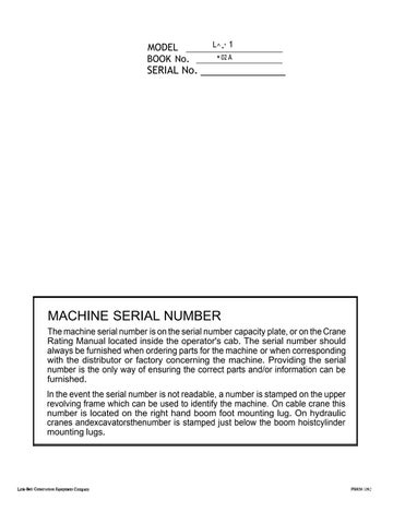
LOWER FRAME Fig. 1
TREAD TAKE - UP ROLLER
TREAD CARRIER ROLLERS
TREAD LOWER ROLLERS
GENERAL DESGRIPTION: Zhe lower frome is of hectvy box Bection, ctll welded construction, intem‹illy reinforced with heovy cross section members 9ivinq great strength and rigidity. Within the lower lrome ore the Tr‹xction Shell end Steering Mechanism.
The oll welded Crciwler Fromes ore welded integral with the moin lower 1r‹ime. Six double flange. bronce bushed, Tre‹id Lower Rollers transmit the machinery weight to the Trend Belt end two doubla Ilonqe Trecid Carrier Rollers on top of eoch irome corry the trend relum. Al one end o1 the ccowler Irome nre the Trend Toke-Up Rollers: on the other end the Trend Drive Sprockels. Power is transierred irom the Trncüon Shell to the Trend Drive Sprockets by the Trnclion Drive Ghnins. The center Inge on the Trend Shoes trctnsfer this power to the Trend Belt.
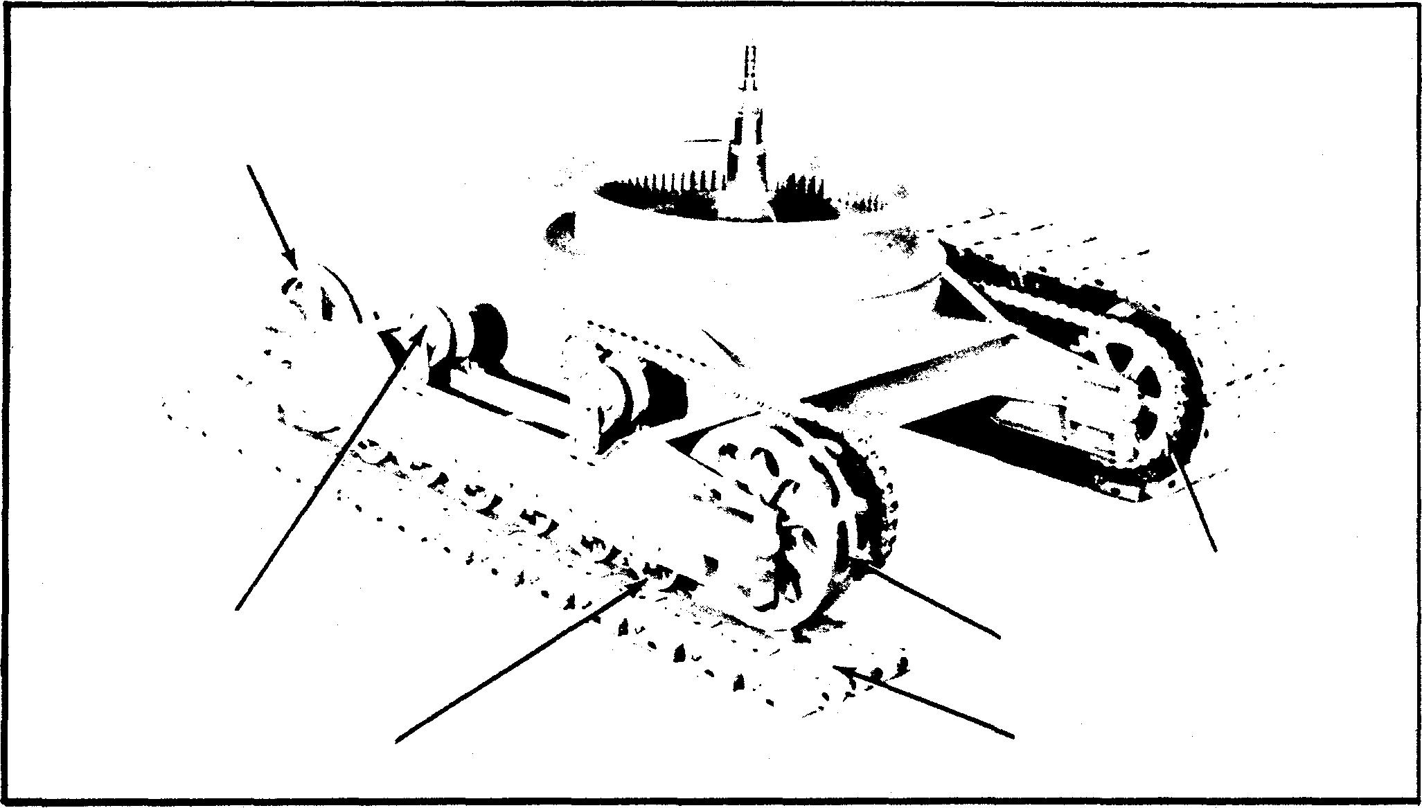
TAKE-UP ROLLER — Fig. 2
TARE UP Ofi TREAD SHOES: As mentioned obove, eoch aide fz'ame cozries its own Tread Shoe 3'oke•Up Roller.
Toke up of wear in ttend shoes is accomplished through means of Trike-Up Bohs. One tcike-up bolt is located on eoch side of Toke Up Roller Sh‹:dt.
Toke up on the trend shoe bells is accomplished in the following monner:
11} Remove Toke-Up Bolt Keepers.
l2) Tighten Take-Up Bolt until proper tension on trend
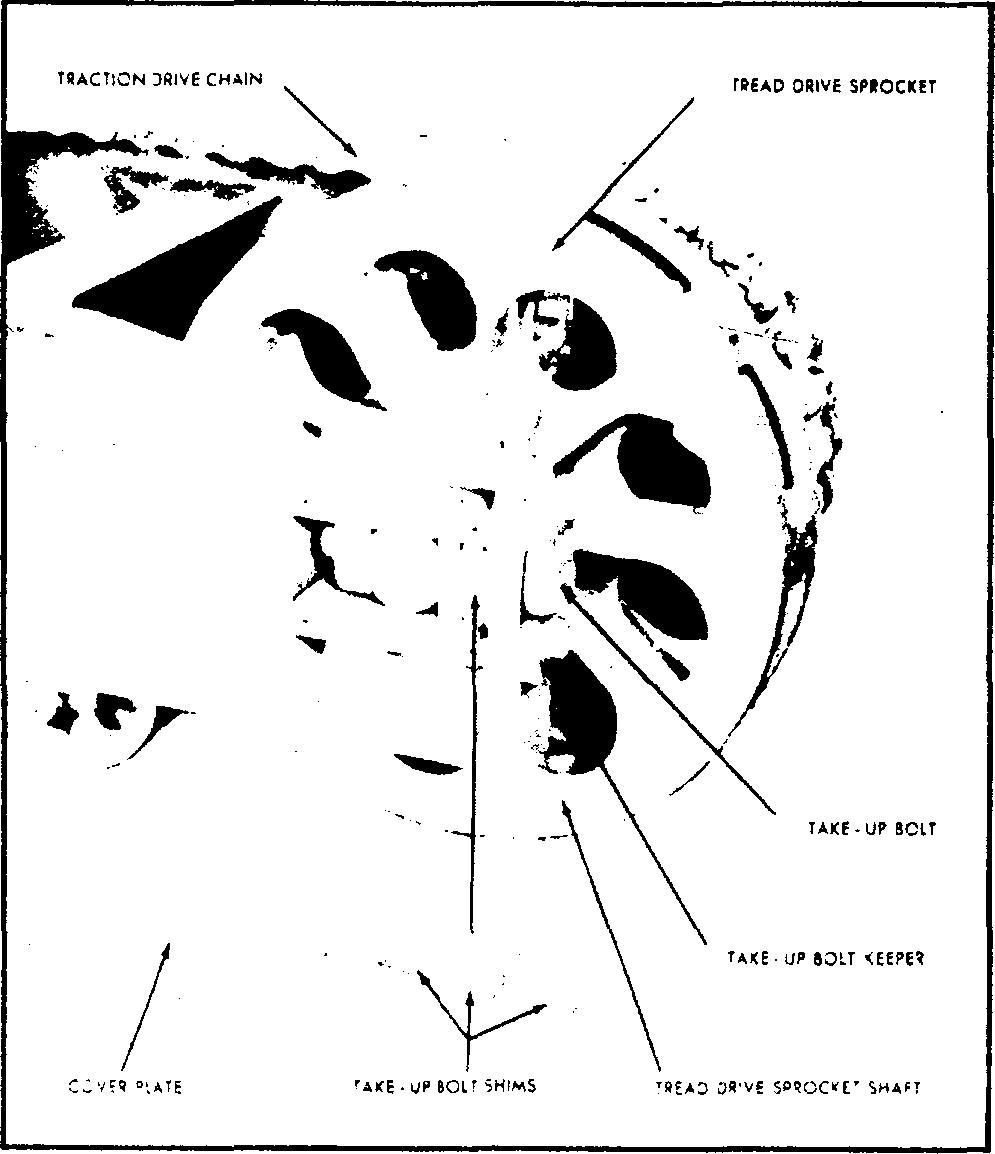
TRACTIOH DRIVE CHAIN
TREAD DRIVE SPROCKET
TREAD SHOES
shoe is oblnined. Since there are two take up bolts on ecich roller ii is importnnl thot the bolls be üqhlened evenly io nssure proper nliqnment. When operoiinq in loose mnleriol or hord pockinq clny,
Fig. I - LOWER FRAME and CRAWLERS
Fig. 2 - TAKE-UP ROLLER

LINK- BELT SPEEDER SERVICE MANUAL
SECTION )
LOWER FRAME Ufi IT Continued
Botts. one located on eacb aide ol Tread Drive Sprocket. When exceesive slack accumulates irt Traction Dztee Chain, take•up on thera in the following ozanner:
(I) Rezaove Cover Plate.
(2) Remove Toke•IJp Bolt keepers.
(3) Loosen Toke•Up Bo1ta and remove Toke•Vp Bolt Sk1osa.
(4) Tighten Toke•f/p Bolta unttl approximately 1" soq in center ol drive chaln ia reached. Since there are two take-up bo\ts on each sprocket it is important thot the bolta be tiqhtened evenly to aaBure proper atiqnzoent.
’i5) Alter proper odlusttnent is obtained Jitl ug gap beMeen Frozne aztd Sprocket Axle with Sblma and tiqhten eecuzely, beinq sura to zeptoca Bolt Eaeper and Cover Plates.
Whezt the above manner oJ chain take-up hoe reached ita maximum (ok ahtma have been removed betweea frame ortd sprocket axle) move Tread Drive Sprocket for• wozd to attain full slack oo Drive Chain and rezaove one link kom chain.
RE5dOVAL AND REA SSEMBL Y OF TREAD DRIVE SPROCBETS: Wheo replacement of Tread Drive Sprocket Buehinqs is necessary. drive sprocket may be removed irt the following manner:
Fig. 3 - TREAD DRIVE SPROCKET
il ia best to keep track shoe belts reloiivelJ BlOCk. This willpermii ci slightomounto1 ”packing" indriveeprockets which will eliminate possibilities o1 breaking trend shoes or pins. However, thia must be watched closely os excessive pecking will result in obnormctlly worn trend sprockets, lreqd shoe lugs and treed shoe pins. II at oll possible when traveling long digtpnces in this type yp. ieriol. the best reaulls will be hod if machine is traveled
• G••*- • •HW$H HDR»
When traveling a considerable diatonce over hard ground or other euch auztocea it is advisable lo peziod• tcalJy reverse the dtzection of the lower crazier ftozne io relation to the upper machinery to prevent uneven weoz onohmoingpoRa
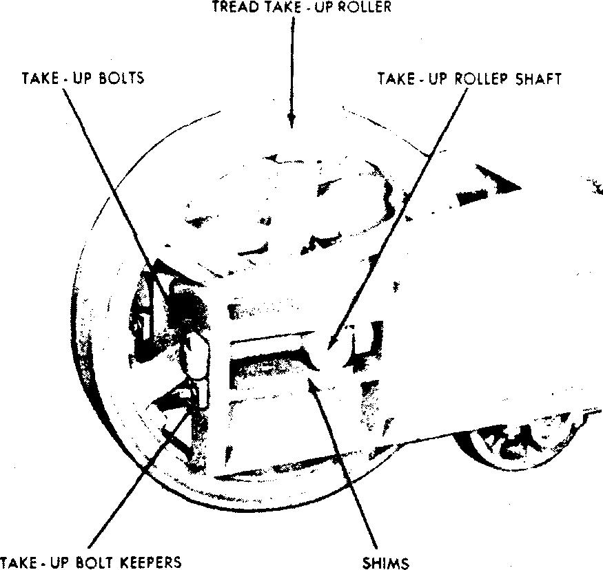
REMOVALAND REAS9EMBLYOFTAE UFROLLERS: Zo remove treed Tele-Up Rollers proceed os follows:
(l) Split Zreod 5hoe Bell.
‹2i nemo•• Z«k«-Up Boit xe»p»ro «nd Toke-Up Bonn.
(3)RemoveShimstrombottomo1take-uprolleraho:ft which wtll ellowthe attest to lower.
IU Bump out 7oke•Vp Roller Skoft izt either d1zectioz
‘i5)Move Toke-Up Roller iorwurd. out or aide frown.
(6)Forinatructiozi•onzeosovolandreploceosentol Tolte•\ipRoll•rBuckingrefer to ”Section I3 Bronxe
17) ReOs&emblY or this unit fs in move reverse order.
TREADDRIVE SPROCKET Fig.3
ADJUSTMENT OF TREAD DRIVE CHAIN: Take up on o •ch•*n^i^•ccomp1lih•d throughoseona o1Zohe-Up 1
(I) Split Tread Shoe Bell.
(2) Split Drive Chain.
t3t Reotove Axle ' ver Plate.
(4) Rezoove Take-'?p Bolt Eeepera aztd YaIze-Vp Bolta.
(5) Remove Sbizos Croat bottom of Drive Sprocket Shaft which will allow the ahah to lower.
(6) Buzop out Drive f2procket Shalt izs either direction.
(7) Move Drive Sprocket forward, out of eide frame•
(8) For instructions removal and replacemeztt ol Tread Drive SprocJcet Bushings refer to ”Section 13 Bronxe Buebinqe
t9) Re•osaetnbly oJ tbie unit ia in above reverae order.
-2