238HSL
CALIFORNIA
Proposition65Warning
Dieselengineexhaustandsomeofitsconstituents,andcertain vehiclecomponentscontainoremitchemicalknowntotheState ofCaliforniatocausecancer,birthdefects,andother reproductiveharm.

238HSL
CALIFORNIA
Proposition65Warning
Dieselengineexhaustandsomeofitsconstituents,andcertain vehiclecomponentscontainoremitchemicalknowntotheState ofCaliforniatocausecancer,birthdefects,andother reproductiveharm.
ThecraneserialnumberisontheCraneRatingManualintheoperatorscab.Theserial numbershouldalwaysbefurnishedwhenorderingpartsforthecraneorwhencorresponding withtheLink-BeltDistributororFactoryconcerningthecrane.Providingtheserialnumberis theonlywayofensuringthecorrectpartsand/orinformationcanbefurnished.
Intheeventtheserialnumberisnotreadable,anumberisstampedontheupperframewhich canbeusedtohelptoidentifythecrane.Thisnumberisonthefrontfaceoftheupperframe betweentheboomfootmountinglugs.
Thefollowingterms/terminology,nomenclature,andabbreviationsaregiventohelp identifycommonterms/terminology,nomenclature,andabbreviationsusedinthis manualthat,duetolanguagetranslations,maynotbeeasilyunderstood.
AuxiliaryHoistingMechanism
BoomPendantRope
CenterJoint
CrawlerShoe
Derricking
DerrickingDrum
DerrickingMechanism
DerrickingMotor
DriveTumbler
HoistingDrum
HoistingDrumControlValve
HoistingMechanism
HoistingMotor
PumpMechanism
Screwed-InConnection
Slewing
SlewingFrame
SlewingMechanism
SlewingMotor
SlewingPump
SlewingRing
Stopper
Take-UpTumbler
TravelMechanism
= AuxiliaryWinchAssembly/WinchDrum = BoomPendants = RotatingJoint = TrackShoe = BoomHoist = BoomHoistDrum
BoomHoistSystem = BoomHoistMotor = TravelDriveSprocket = WinchDrum = WinchDrumControlValve = WinchAssembly/WinchDrum = WinchMotor = PumpAssembly = ThreadedConnection = Swing = UpperRevolvingFrame = SwingReductionUnit = SwingMotor = SwingPump = TurntableBearing = Plug = TrackTake-UpIdler = TravelMotorandReductionGears
Upperstructure = CraneUpper
Thismanualiswrittenforanexperiencedtechnician toprovidetechnicalinformationneededtomaintain andrepairthismachine.
Besuretothoroughlyreadthismanualforcorrectproductinformationandserviceprocedures.
Pleaserefertothematerialslistedbelowinaddition tothismanual.
TheOperator’sManual
ThePartsCatalog
PAGE NUMBER
Each page has a number, located on the center lowerpartofthepage,andeachnumbercontains thefollowinginformation:
Example: W1-3-5
OperationManualoftheEngine
PartsCatalogoftheEngine
HitachiTrainingMaterial
ConsecutivePageNumberforEachGroup
GroupNumber
SectionNumber
W:WorkshopManual
Inthismanual,thefollowingsafetyalertsymboland signal words are used to alert the reader to the potentialforpersonalinjuryofmachinedamage.
Thisisthesafetyalertsymbol.Whenyouseethis symbol,bealerttothepotentialforpersonalinjury. Neverfailtofollowthesafetyinstructionsprescribed alongwiththesafetyalertsymbol. Thesafetyalertsymbolisalsousedtodrawattention tocomponent/partweights. Toavoidinjuryanddamage,besuretouseappropriate lifting techniques and equipment when lifting heavyparts.


SIUnits(InternationalSystemofUnits)areusedin thismanual.
MKSA system units and English units are also indicatedinparenthhesesjustbehindSIunits.
CAUTION: Indicated potentially hazardous situation which could, if not avoided, result in personal injury or death.
IMPORTANT:
Indicatesasituationwhich,ifnotconformedtothe instructions,couldresultindamagetothemachine.
NOTE: Indicates supplementary technical information or know-how.
Example:24.5MPa(250kgf/cm2,3560psi)
AtableforconversionfromSIunitstoothersystem unitsisshownbelowforreferencepurposees.
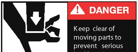
Keep hands and tools clear of moving parts.
Remember SAFETY every day. Someone's LIFE may depend on it, MAYBE YOUR OWN. Safe operations of a crane requires a well trained, qualified operator. Crane operation is more involved than it may appear, and operation by a careless or unqualified person can result in a serious accident.
When a crane is maintained and used properly it can be a safe, highly productive piece of equipment, but if not used properly, it can be dangerous. Think Safety - You, the operator, are in charge of an important piece of equipment. It is very important that you know what it can do. It is also important that you know what it should not do. No set of instructions can anticipate all of the situations you will encounter. The rules given here cover the general usage, and some of the more common specific cases. If conditions arise not covered by these rules, contact your Link-Belt Distributor. A phone call could save someone's life.

The following is a list of safety rules which should be followed during all crane operations.
1. Read, understand, and follow all instructions given in the Operator's Manual. The Operator's Manual contains critical information for operation and maintenance of this crane.
2. An operator must not eat, read, or otherwise divert his attention while operating a crane. Remember operating is a full-time job.
Confirm the load will clear any obstructions.
3. Don't smoke when fueling or fuel up near an open flame. Keep the nozzle in contact with the filler neck to prevent static electric sparks. Shutdown the engine when fueling.
4. Start and operate engine in a well ventilated area. Diesel exhaust fumes can be harmful. If it is necessary to operate in an enclosed area, vent the exhaust to the outside. Properly maintain the exhaust system to its original design.
5. Keep your shoes clean. Before entering the operator's cab, wipe clean any mud, gravel, snow, ice, moisture, or grease from your feet. Slippery shoes could cause momentary loss of control of crucial foot operated controls.
6. Keep all walking surfaces (steps, ladders, platforms, etc.) on the crane clean. These are to assist operators and service personnel with safe access/egress to/from the crane and to/from adjustment and inspection areas. Do not allow walking surfaces to become contaminated with mud, snow, ice, oil, paint, wax, etc. Any contamination can cause the walking surfaces to become slick, reducing their effectiveness for safety while walking on the crane.
7. Keep fingers, feet, and clothing away from sheaves, drums, and wire ropes unless the crane is shutdown and everyone knows what you are doing. Do not place a hand on wire ropes when climbing on the crane. A sudden movement could pull them into the drums or sheaves. Do not wear loose clothing which may be caught in machinery.

8. The operator and person in charge of the load must observe the following rules:
a. Loads must be well secured before lifting. Confirm that the rigging cannot slip off or pull away from the load, or get out of position on the load. Ensure the load is rigged so it will not turn over.
b. Chains and slings must be of adequate size, in good condition, and not twisted around each other.
c. The load must not catch on an obstruction when lifting or swinging. Ensure the load, hoist wire rope, or any other parts of the crane do not snag or strike any obstruction.
d. Do not allow the load to rotate out of control. Personal injury to ground personnel, load damage, crane damage, or damage to anti-two block system may occur.
e. When hoisting with single part line, especially in long falls applications, the design of wire rope and hook ball is crucial to minimize the potential for uncontrolled wire rope and/or load rotation. Rotation resistant wire rope is recommended for single part of line applications. See the Wire Rope Capacity Chart in the Crane Rating Manual for the specific types of rotation resistant wire rope recommended for the crane.
f. Avoid sudden starts and stops. Lift carefully, swing gently, brake smoothly, lower and set loads carefully. Jerking the load, swinging and engaging swing brake roughly, and lowering the load rapidly and slamming on brakes, will put shock loadings and possible side loadings on the boom. Unnecessary abuse labels the operator as a beginner. Be a professional.
g. Do not wrap the winch wire rope around the load. Do not use discarded, worn, or damaged wire ropes for slings. They may break and drop the load.
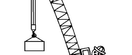
h. The crane must be level on a firm supporting surface before making a lift. Remember, a three degree side tilt can reduce capacities by 50% or more.

The hook block and/or hook ball and hoist wire rope can be used as a plumb bob to level a crane. Pick up a compact load 2,000-3,000 lb (907-1 360kg) a few inches (centimeters) above the ground. If crane is level, hoist wire rope will hang directly between the boom foot. Now swing over the side. The wire ropes should still hang directly between the boom foot. Be extra careful when using this method on a windy day.
A3 Degree Side Tilt Can Reduce Capacities By Over 50%. Grade Ground Level Or Block Under Crane. The Load Should Hang Parallel With The Boom. Figure 1 4 Level the crane.
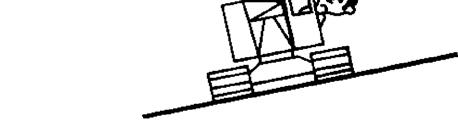
Just A Little Bump Like This ........
Do not use the boom to pull sideways.
9. Don't let the load or bucket hit the boom or jib. Don't let the boom or attachment rest on, or hit, a building or any other object. A dent or other damage could result, which will weaken the boom or attachment. If the damage is major, the attachment could collapse. If a lattice or diagonal bracing member on the boom or jib is broken, cracked, or bent, contact your Link Belt Distributor for repair procedures. If the boom or jib is struck or damaged by anything, STOP. The loading on a boom or attachment increases as they are lowered, therefore their suspension systems could collapse during lowering. Use another crane to lower a damaged boom or attachment.
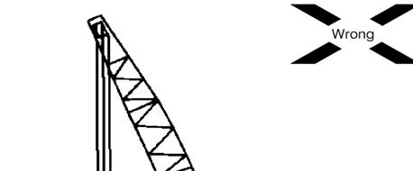
10. Don't pull sideways on the boom or jib, not even a little. Lift straight up on every load. Moving trucks, rail cars, barges, or anything else pulling sideways on the winch wire rope could buckle the boom or jib. It could also damage the swing mechanism. Pulling sideways on a boom or jib can overturn the crane.
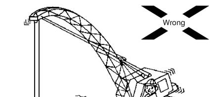
11. Do not two block (pulling the hook block, hook ball, or load into the head machinery) as this can cause winch wire rope breakage, sheave damage, or could pull the boom backwards over the crane resulting in an accident.

12. Ensure the boom hoist pawl is engaged except when lowering the boom. Don't rely on the boom hoist brake alone to hold the boom. Wear, improper adjustment, water or oil on linings, and many other factors may affect the ability of the brake to hold the boom.
13. Watch the load or a signal person at all times. A suspended load must have your undivided attention.
14. Operate the crane from the operator's seat only. Operating the crane from any other position, such as reaching in a window, constitutes a safety hazard.
15. After slack winch wire rope operation, confirm that the winch wire rope is properly seated in sheaves and on drums before continuing to operate. Use a stick or mallet to set the winch wire rope, not your hands.
16. Do not lower the load beyond the point where less than three full wraps of winch wire rope are left on the drum. This condition could occur when lowering a load beyond ground level. If all the winch wire rope runs off the drum, the load will jerk which could break the winch wire rope.
17. Confirm that there is a safety latch on the hook, and that it works properly. Without a latch, it is possible for slings or chains to come off the hook, allowing the load to fall.
18. Don't alter any part of the crane. Additions to, or changes in, any part of the equipment can create loadings for which the crane was not designed. Such changes may have a major affect the usable capacities and make the entire capacity chart invalid. Such changes can dangerously overload or weaken critical parts and may cause disastrous failure.
19. Do not exceed the rated capacities of the crane under any circumstances. While a crane has more stability when lifting over a corner (as compared to straight over the side) the crane capacity is not increased. Any time the load exceeds the rated capacities listed on the capacity charts in the Crane Rating Manual, the crane is overloaded. Overloads can damage the crane and such damage could cause failure and accidents.
20. Lifts where two or more cranes work together can be hazardous and should be avoided. Such lifts should be made only under the direction of a qualified engineer. If a multiple crane lift is unavoidable, observe the following rules:
a. The cranes must be level and positioned on firm surfaces.
b. The cranes should be the same size and capacity, use the same boom length, and be reeved similarly.
c. Cranes must be positioned so that each boom point is directly over its load attaching point. The winch wire ropes must be vertical during all phases of the lift.
d. The rigging must be placed so each crane lifts a share of the load well within the crane's capacity.
e. Ensure that during handling more load is not transferred to any crane than it can handle.
f. Don't attempt to travel when making multiple crane lifts.
g. Coordinate plans with the other operator before beginning to lift.
h. Use only one signal person.
i. Use of an operable load and angle indicating system is desirable.
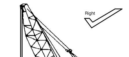
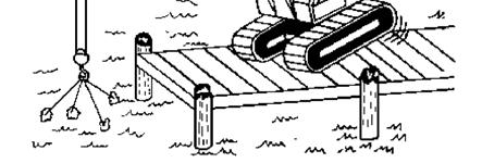
21. When operating a crawler crane, where the tracks sink into the soil any noticeable amount, use matting. Timbers used for matting should be at least as long as the total width of the lower and should be heavy enough to withstand loadings without damage. Timbers should be close enough to form a solid platform when lifting over lower ends (or raising and lowering attachment). Block under track ends so full support is provided where tracks leave the ground. This helps keep the tracks from digging in and cuts down on crane rocking.
22. When operating over the front or rear, use care not to hit the lower with the load or boom.
23. When lifting submerged loads, the suction caused by the load resting on the bottom acts to increase the weight of the load; in some cases the actual load weight. This same effect can occur on land, when a load is embedded in mud. To break a load loose from suction, dont pull sideways or the boom may collapse. If possible, rig the load so it is lifted from one end. Dont jerk on the load. A steady pull, maintained for several minutes, will often free the load without over loading the equipment.
When a submerged load reaches the surface, dont attempt to lift it out of the water all at once. It may be saturated with water and will weigh many times what you expect. Allow it to drain as you raise the load slowly. Be patient, as draining may take a long time. A load when removed from the water, will have a greater effective weight than it will when submerged because of buoyancy.
24. Dont extract piling, casings, or other such loads by jerking on them. The practice of pulling on the load until the crane has tipped, then releasing the hoist wire rope, allowing the crane to drop back and catching the hoist wire rope on a clutch or brake may break the boom. If the piling or casing wont pull out with a smooth, steady pull, use an extractor, pulling frame, or similar rigging intended for this purpose. Pulling on a load that is not free to be lifted can develop loadings on the crane far in excess of the normal weight of the load. Lifting such loads on a crane can damage the crane and may cause disastrous failure. When using a pile extractor, use a shock or vibration insulator unit.
25. Operating with auxiliary equipment such as pile driver leads, pile hammers, or caisson boring attachments imposes additional loading in the crane. This causes a major reduction in lifting capacities of the crane. Changes in auger and Kelly bar lengths with drilling attachments and in pile hammer attachments further complicate the manner in which lifting capacities are reduced. The weight of each piece of auxiliary equipment is to be considered a part of the live load acting at the radius of the center of gravity of the piece.
26. Demolition work can be particularly hazardous. Shock loadings and side loadings from demolition ball and clamshell bucket work can be severe. The repetitive nature of such work imposes heavy demands on all parts of the crane. Restrict demolition ball weights to 50% of crane capacity, with the boom length you are using, at maximum load radius. In no case however, should the ball weight exceed 50% of the available line pull.
27. When using demolition ball, avoid sudden clutch and brake applications. Work steadily and smoothly. Dont try to knock the whole structure down with one blow. Use good aim. If the ball misses its target, out swing could cause crane tipping or overload. When swinging back, the ball may hit the boom and damage it.
28. Do not use the jib for demolition, drop ball, drag line, clamshell, or any other type of duty cycle application.
29.When using a clamshell bucket on demolition work and taking a bite on a piece of unknown weight, be ready to release the closing line as more weight than can be lifted may break loose. Be prepared to drop the load. Always remain within the boom length and load limitations shown in the Crane Rating Manual. Failure to do so may fatigue components which can lead to eventual failure.
30.When dismantling a structure where a portion is being cut loose while suspended by a crane, confirm that the weight of the portion being cut loose is known, and the crane pull on the load is equal to the weight. The point of attachment must be directly above the center of gravity of the load. The hoist wire rope must be vertical. This is an extremely hazardous operation. The services of a professional engineer should be used to plan and supervise such lifts.


31.Cold weather operation requires some special attention by the operator to allow for changes in everyday routines:
a.Clean all snow and ice from all steps, ladders, platforms, etc. to eliminate slippery walking surfaces.
b.Clean the crane, especially the boom, of accumulated amounts of ice or snow. Operating the crane with an ice or snow covered boom is dangerous. The added weight of the ice or snow can drastically reduce the capacity of the crane. Also, falling ice may pose danger for ground personnel.
c.If cold weather starting aids are provided on the crane, use them. The use of aerosol starting sprays can be dangerous if the manufacturers directions are not closely followed.
d.Pay close attention to the gauges in the operator's cab when starting the engine. Normal warm up times will be longer. Ensure pressures and temperatures are within normal ranges before beginning operations.
e.Always handle flammable materials according to the suppliers instructions. Propane, diesel, or other fuel, for auxiliary heaters, can be dangerous if not properly handled. Do not store such fuels on the crane.
f.Use caution when lifting any load during freezing weather, as it may be frozen to the ground or the supporting surface. The added tension, to break the load free, could cause an unexpected overload situation. Also, when the load does finally break loose it could create an erratic motion causing damage or injury.
g.At the end of the work shift, park the crane where it will not freeze to the ground. Major damage to the drive train could occur while trying to free the crane from a frozen surface.

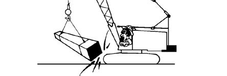
Disassembly of any pin connected boom can be hazardous. Removing the wrong connecting pins or removing the connecting pins without first properly positioning pendants will cause the boom to fall. If you are under the boom when it falls, you may be killed. If there is any doubt in your mind about the boom disassembly procedure, block tightly under both ends of each boom section before removing any of the connecting pins.
The following points must be observed while performing any boom assembly or disassembly:
1.Read and understand the step by step instructions outlined in the Operators Manual before attempting to assemble or disassemble the boom.
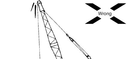
2.Do not stand inside, on top, or under the boom at any time while assembling or disassembling the boom.


3.Do not climb, stand, or walk on the boom. Use a ladder or similar device to reach necessary areas.
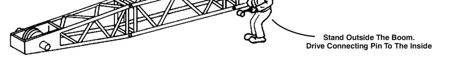
4.When removing or installing the boom section connecting pins, drive the pins from outside the boom toward the inside.