Height sensor
Notes: For the installation of the height sensor, you need to watch the movement of the suspension under the car, this process should be completed with the help of jack. Fig.6-1 shows the distance of some points of the suspension arm when it moves up and down. The distance can't be too near or far away from the point O. "A" is very near rotation point O, then it almost has no space to move, "B" is far away from point O, it has enough space to move, but it may damage height sensor or linkage(Fig.6-2). 1.Find a desirable mounting point (name as"X") at the suspension, use it as the datumpoint in the following measurement(Fig.6-3). 2.Draw a comma at a corresponding place of the suspension arm under X(It will be the mounting location for the bolt of the linkage). 3.Rise the vehicle to the highest position, name the distance from X to the comma as A(Fig.6-4). 4.Lower the car to the lowest point, name the distance from X to the comma as B(Fig.6-5).The distance of the sensor movement is A minus B(Fig.6-5). 6.Install
A B 0 Fig.(6-1) Fig.(6-2) Keep proper drip loops and use proper bend radius for wire bundles HEAD 120mm 04
5.If the movement distance is shorter than 120mm,then move the two points (X and the comma) a little far away from the rotation point of the suspension arm, repeat step 1, step 2 and step 3. Ifthe movement distance is longer than 120mm, then move the two points a little nearer to the rotation point of suspension arm, repeat step 1,step 2 and step 3. It' s hard to adjust the distance to 120mm accuratly, keep the distance below 120mm,not above 120mm(Fig.6-6). 6.Regulate the mounting hole, drill or weld a hole for mounting bolt of the linkage at appropriate place(Fig.6-7). 7.Mount one end of the linkage to the suspension arm with a bolt, move the suspension arm to the middle place between the highest and lowest position, adjust the swing arm of height sensor to close zero angle with the centerline of sensor body, choose a appropriate connecting location with another end of the linkage, cut the linkage appropriatly, connect it to the mounting hole of the swing arm(Fig.6-8).05 suspensin chassis suspension arm A Fig.(6-5)Fig.(6-4)Fig.(6-3) B
8.Connect the swing arm and the linkage with a bolt, and then find a mounting ocation, draw the installation profile of the sensor, drill two holes to mount it (Fig.6-9). 9.Lower your vehicle to the lowest position(Fig.6-10) and rise it to the highest position(Fig.6-11). Check whether the height sensor is in the appropriate location, if not, adjust the linkage to get the appropriate location(Fig.6-9). 10.Confirm the number of each height sensors according to the annexed figure I(the diagram of connecting wiring), connect the corresponding height sensors(Fig.6-12). The lowest position of suspension Cut length The middle position of suspension The highest position of the suspension The middle position of suspension The higheest position of suspension The lowest position of suspension Fig.(6-12)Fig.(6-11) Fig.(6-8) Fig.(6-9) Fig.(6-10) Fig.(6-7) Fig.(6-6) Rotary Position Sensor # 06
Notes:Connect the cable harness according to mark correctly. Press hard until you hear click of lock. Mind the sharp-edged metal,the cable harness may be insulated,use U-shaped wrapping strips to protect it. There are two sets of relay control which can be used at the same time. If you just need one, connect either of them. 1.Connect ECU with the main harness, then distribute each branch to corresponding component according to the diagram of connecting cable(Fig.10-1). 2.Connect air compressors with power cords: connect the fuse end of the red principal line with the positive pole of vehicle battery and connect the other end with relay terminal which marked "B+". 3.Connect the cable which marked "ACC+" with vehicle ignition power. 4.Connect the cable which marked "Valve#1" and "Valve#2" with the manifold. 5.Connect the cable which marked "Relay Control 1" and "Relay Control 2" with "Relay control" of the relays. 6.Connect the cable which marked "Rotary Position Sensor 1&2" with the corresponding cable joint which marked "Rotary Position Sensor 1&2"(1 means left rear, 2 means right rear). 7.Connect the cable which marked "Rotary Position Sensor 3&4" with the corresponding cable joint which marked "Rotary Position Sensor 3&4"(3 means left front, 4 means right front). 8.Connect all the cables which marked "B-" to the ground(car body metal). 9.Fasten GPS antenna and ECU,then fasten the antenna in a position which receives GPS signal well. 7.Install cable harness 07


9.Installation Software H1 User H1 Setup 10. Test and adjust Notes: The engineer version of H1 APP is appropriate for the people who install and debug the H1 air suspension system. The user version of H1 APP is appropriate for end users. Download H1 APP in Apple Store. The H1 air suspension system must be setup and debugged by the engineer version of H1 APP first, otherwise the remote controller or the user version of H1 APP can't control normally. Notes: Connect the air line with suitable components correctly. Mind the bend angle of the air line which may cause jam or damage to the air line. Use U-shaped wrapping strips to protect the air line against sharp edges of other parts. 1.Install air line according to the diagram of connecting air line(Fig.10-2). 2.The ports of the manifold connect as follows: "TANK" connects the tank, "EXT" connects silencers, "1"connects left-rear air bag, "2" connects right-rear air bag, "3" connects left-front air bag, "4" connects right-front air bag. 8.Install Air Line Notes: Use the engineer version of H1 APP to test and adjust. Make sure there is no any obstacles above and under the vehicle before "FULL-AUTOMATIC ADJUSTMEN" start. 1.Check the connection of air line and connectors of each parts, start the car and check whether the air compressors work, whether there is any leakage, whether the system is under control. 2.Turn the operating device WIFI on,connect HF-LPB100 and enter the password(The password consists numbers and uppercase characters, which is under the bar code of the packaging box or ECU housing label.) 02
H1 app(Fig.10-1).
the Max.Pressure of the tank, press "SAVE" after inputting the value(145psi is suggested,the Max. Pressure can' t be above 200psi)
the Min.Pressure of the tank, press "SAVE" after inputting the value.(The value must be below the Max.Pressure).
"Height hysteresis" ,press "SAVE" after inputting value. "Height hysteresis" means the control system adjusts the car height within the range of error when the height value of car minus the system setting value ,which is above height hysteresis. 4% is suggested during the installation; 8% is suggested after installation.Then give the users to use(Different kinds of cars may have different installations).
buttons in the middle are adjustment functions.

ADJUSTMEN": the control system adjust full automatically. Before start, make sure there is no any obsta cles above and under the vehicle. During the adjustment, the vehicle will be risen to the highest position and lowered to the lowest position, press "STOP" if any abnormalities occur. After the process, the app will popup the result, if succeed, the vehicle will be adjust to COMFORT mode, if not, there are problems with the hardware check the simple troubleshooting.
ADJUSTMENT": adjust the system manually.Fig.(10-2)
3.Enter
4.Set
5.Set
6.Set
7.The
8."FULL-AUTOMATIC
9."MANUAL
09
to
FULL-AUTOMATIC ADJUSTMEN:
"STOP" if some
in the
after the
can
will
MANUAL ADJUSTMENT:
of
MANUAL ADJUSTMENT:

MANUAL
10.2.4.3 ADJUST THE HEIGHT SLIGHTLY:
tment
Switch to fine tuning interface(Fig.16).OFF ROAD mode and COMFORT mode,SPORT mode, ULTRA LOW mode,HIGH SPEED mode can be chosen respectively. Adjust each mode can balance the car and get the best performance.Press SAVE after adjusting each mode which can be effective.
(Fig.16)HIGH SPEED is a special mode which is set by the system that when the speed exceeds a certain speed,the system will adjust the height of the vehicle body automatically which can reduce wind resistance and improve comfort. The height of High speed mode is a little lower than that of SPORT mode.
10Fig.(10-1) 10.2.4.1
Click" AUTOMATIC ADJUSTMENT",the control system starts
adjust full automatically. During the adjustment, you
press
abno rmalities occur. The system
be
COMFORT mode
completion
the full-automatic adjustment. 10.2.4.2
Click" MANUAL ADJUSTMENT",then manual adjus tment can be conducted. 10.2.4.2
Click"
ADJUSTMENT",then manual adjus
can be conducted.
11.Simple troubleshooting Start the automotive system,no action The compressor doesn' t work The compressor couldn' 't stop working. Operate the controller,the system has no reaction Operate by smart phone or intelligent devices, the system has no reaction Automatic adjustment unsuccessfully The ACC positive and negative terminals of the main harness aren' t connected correctly Check and connect the ACC positive and negative terminals correctly according to the annexed figure I (Diagram of connecting cable) 1.The battery positive and negative terminals of the relay are not connected correctly 2.The 50A fuse of positive power cord is burn out 1.Check and connect the battery positive and negative terminals of the relay correctly according to the annexed figure I(Diagram of connecting cable) 2.Replace 50A fuse after checking no short circuit 1.Check and re-connect the air line with leakage 2.Connect the air line orrectly according to the annexed figure II(Diagram of air line) 1.Leakage in air line 2.Air line is connected to wrong place Shut off the car restart after a few seconds.Press the on/off switch(identification key)of the controller to match again The controller and ECU doesn' t match successfully 1.Install the height sensor according to installation steps correctly 2.Connectheight sensor connector according to the annexed figure I (Diagram of connecting cable) 3.Connect air line according to the annexed figure II (Diagram of air line) 1.The installation of the height sensor isn' t reasonable 2.Wrong connection of the height sensor connectors 3.Air hose is connected to wrong place Need password whe nconnecting WIFI.The password is on the ECU label.Please operate after connecting WIFI WIFI isn' t connected. 11
Notes:
Cut all air line ends as squarely and as smooth as possible. Bad cuts may cause leakages. Auto water trap must be installed vertically. Wrong positions may cause failures. It's necessary to install a check valve between auto water trap and the tank.Connect two wires of auto water trap with air compressor wires one-to-one. The check valve is installed at the air compressor air line when you get it.
Use thread sealing glue or Teflon tape moderately. Too much of them may cause damage or jam.
12
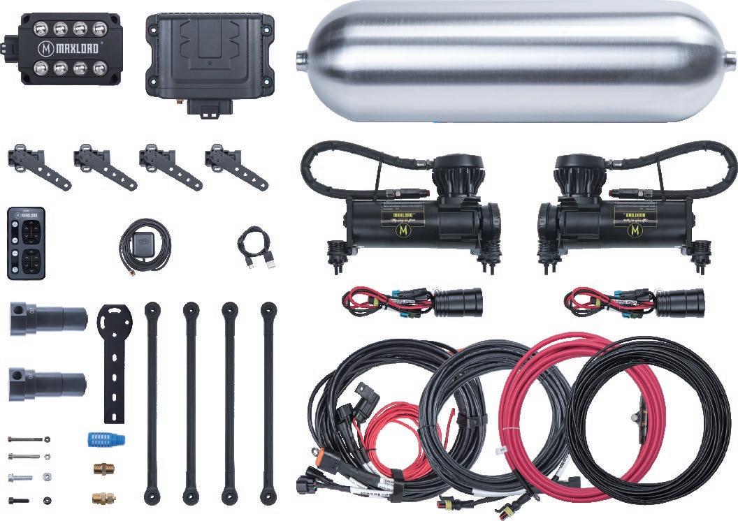
ECU-H1 MANIFOLD V680 compressors V680 compressors 15A 50A 50A 3LF 4RF HEIGHT SENSOR 4HEIGHT SENSOR 3 TO GROUND HEIGHT SENSOR 2HEIGHT SENSOR 1 1LF 2RR RELAY CONTROL 1 RELAY CONTROL 2 ACC+ BATTERY - + TO GROUND POWERAnnexed figure 1 Cable harness diagram 13


FR RR V680 compressors LR V680 compressors Annexed figure 2, Air line diagram FL TANK2 2 3 1.1/4”NPT-1/4” 2.1/4”NPT PLUG 3.Safety Valve 4.1/4”NPT-1/4” 2 3 1 MANIFOLD 1 14
gangster
OG 40 years ago since 1982 , 1st GEN OEMOriginal Equipment Manufacturer Spirit Original
OPERATION OF REMOTE CONTROL 18 17 1 5 6 2 3 7 8 4 9 13 14 10 11 15 16 12 19 1.OFF ROAD 2.COMFORT 3.SPORT 4.UTRAL LOW 5.FRONT LEFT UP 6.FRONT LEFT DOWN 7.REAR LEFT UP 8.REAR LEFT DOWN 9.FRONT AXLE UP 10.FRONT AXLE DOWN 11.REAR AXLE UP 12.REAR AXLE DOWN 13.FRONG RIGHT UP 14.FRONG RIGHT DOWN 15.REAR RIGHT UP 16.REAR RIGHT DOWN 17.CHARGE/TRANSMITTING INDICATOR LIGHT 18.ON/OFF SWITCH(Identification key) 19.MICRO USB CHARGE PLUG15
Instruction wireless remote control: 1.Charge: Fast charging up the remote control by Micro USB charge plug.Red light means it's on charge,green light means it's fully charged. 2. Remote control identifies the air suspension ECU Press ON switch and start the car, press identification key to transmit identification signal.When the blue light is on,then identification is completed.It's completed in 15 seconds after the car is started.If not completed,restart the car and repeat the process. Just identify for once, then use forever. 3.Function operation of remote control 3.1 Four auto modes for your choice: OFF ROAD,COMFORT,SPORT,ULTRA LOW ( Please don't switch mode when driving in highway.) 3.2 Adjust the four wheels manually and separately: Touch the corresponding up or down key to adjust freely and get the height what you need. ( Please don't switch mode when driving in highway.) Warm Reminder:The remote controller should be operated near the air suspension system. For long distance control, mobile phone or other intelligent devices are recommended. 16
OPERATION OF INTELLIGENT DEVICE
OPERATION:
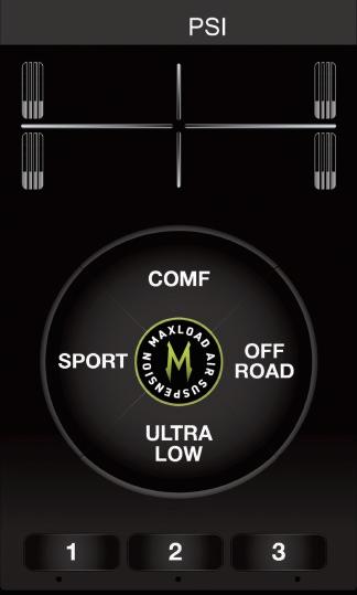
17 Turn the operating device WIFI on, connect HF-LPB100 and enter password.(The password is numbers and capitals, which is under the barcode of the packaging box or ECU housing label.)Click User software into operation interface. When the car is started or running,you can click the key“ OFF ROAD" on the user interface, then the system will be adjusted to OFF ROAD mode automatically. When the car is started or running, you can click the key"COMFORT",then the system will be adjusted to COMFORT mode automatically. COMFORT mode is default when you start the car. COMFORT. When the car is started or running,you can click the key" SPORT" on the user interface,then the system will be adjusted to SPORT mode automatically. When the car is started or running, you can click the key "1", "2" or "3" on the user interface,thenthe system will be adjusted to custom mode automatically. BASIC
1.OFF ROAD MODE: 2.COMFORT MODE: 3.SPORT MODE: 4.CUSTOM MODE:
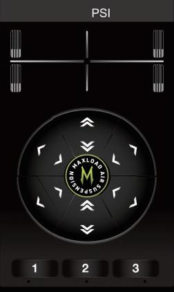
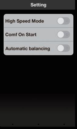
ULTRA LOW is a mode that set by installation person which can be chosen to use but can't be set by users. Slide the UI to enter manual mode. You can set every pressure of the 4 air bags to the value you want by clicking the relative arrow buttons. 5.ULTRA LOW: 6.MANUAL: Set the values to what you want and long press "1" , "2" or "3" to save. 7.1/2/3 CUSTOM SET: Notes:Please don't use "ULTRA LOW" mode when the car is running! 8.high speed mode: 9.comf on start: 10.automatic balancing: "HIGH SPEED MODE" is a special mode set by the system. When the speed exceeds 135km/h, the system will adjust the height of the vehicle automatically which can reduce wind resistance and improve comfort. The height of High speed mode is a little lower than SPORT mode. The system change to comfort mode automatically every time you start the vehicle. The system adjust automatically when the loads of 4 air springs change. WARNING: PLEASE COMPLY WITH THE LOCAL SPEED LIMIT. 18
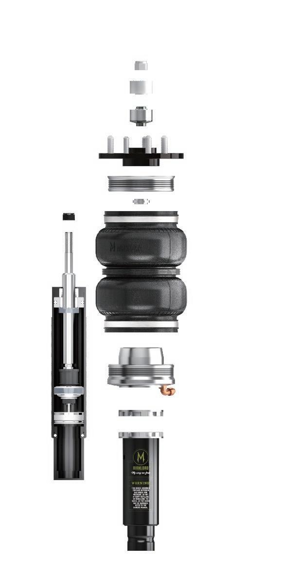
INSTALLATION MAUAL PLEASE INTRODUCTION THE SYSTEM ADOPTS WIFI INTELLIGENT CONTROL AND WIRELESS TOUCH CONTROLLER , WHICH CAN ADJUST THE HEIGHT OF FOUR AIR SPRINGS FAST AND ACCURATELY AND MAKE THE VEHICLE AND ROAD CONDITION THE BEST MATCH. THEN YOU CAN EXPERIENCE THE COMFORT AND FUN OF DRIV ING ALL THE WAY.THERE ARE FOUR DIFFERENTMODES FOR YOUR CHOICE. 1.COME 2. SPORT 3.ULTRA LOW 4.OFF ROAD READ THE MANUAL CAREFULLY BEFORE START https://www.maxloadstance.com/