ELECT RICIAN &INSTALL ER


at
How to record the details of protective devices on the
What sort of RCD circuit protection should be associated with Mode 4 charging equipment?
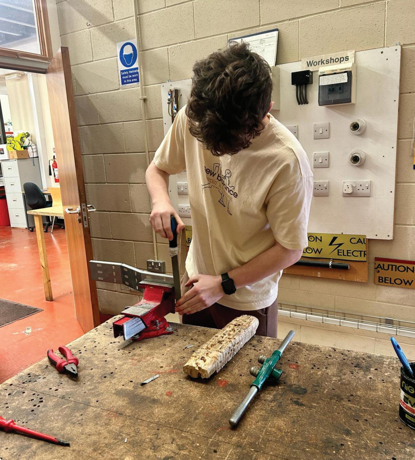
17 How to fix PV arrays to on-roof solar photovoltaics systems
20 Some essential pointers when working with DC circuits
22 Why is the arc flash boundary so important?

41 Considerations that should be made for the selection and erection of electrical accessories in locations that are subject to mechanical impact
42 How have loop tests evolved over the last 40 years?
44 The team at NAPIT give our reader submissions the ‘Codebreakers’ treatment
46 Dr Zzeus, Tom Brookes, answers another fire safety-related question from the field
48 The ultimate guide to Surge Protective Devices (SPDs)
51 Considering the requirements for the use of medical IT systems within a Group 2 location
55 Discussing the concept of parasitic capacitance in solar PV installations
58 NICEIC’s team of expert, technical engineers answer key questions from the industry
60 How to ensure you are carrying out Portable Appliance Testing correctly
62 The team at NAPIT give our readers submission the ‘Codebreakers’ treatment
65 The factors to be considered when providing protection against overvoltage in a domestic premises having a service fuse of rating not exceeding 100 A per phase
68 The considerations professionals need to make when sourcing appropriate ventilation equipment for the application/environment in question
70 What is neutral current diversion (NCD) and where is it most likely to occur?
72 The team at NAPIT give our reader submissions the ‘Codebreakers’ treatment
74 Dr Zzeus, Tom Brookes, answers another fire safety-related question from the field
75 The requirements for the protection against electric shock in medical locations
78 The key responsibilities that will ensure tenant safety and legal adherence with the PRS electrical safety check requirements
80 A look at the requirements for Type B RCD use in heat pump installations
82 The team at NAPIT give our reader submissions the ‘Codebreakers’ treatment
84 The experts at NICEIC answer more of your FAQs
85 A closer look at fault currents
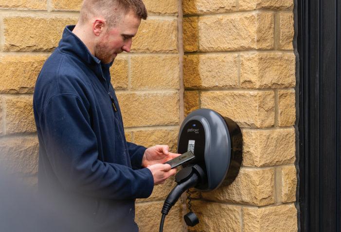
86 What do you need to consider before installing EV charge points?
89 Analysing the installation of cables within containment systems
92 What must be taken into account when selecting protective devices for use in applications where bidirectional power flow is to be expected in normal operation?
Editor
RICHARD BOWLER
email: pe@hamerville co uk
Digital Manager
REBECCA MCGEOCH
email: rmcgeoch@hamerville co uk
Digital Assistant
ADAM ROBERTS
email: aroberts@hamerville co uk
Advertisement Manager
ANTHONY SCOTT
email: ascott@hamerville co uk
Assistant Advertisement Manager
IAN TURNER
email: ianturner@hamerville co uk
Design
GEMMA WATSON
Production Assistant
KERRI SMITH
Group Production Manager
CAROL PADGETT
Distribution Manager
KARL CLARK
Printed by:
PCP TELFORD
Published by:
HAMERVILLE MEDIA GROUP
Regal House, Regal Way, Watford, Herts, WD24 4YF
Tel: 01923 237799
Fax: 01923 246901
Email: pe@hamerville co uk
PROFESSIONAL ELECTRICIAN is the business journal for the electrical contracting industry It is available to the trade at leading electrical wholesalers throughout the UK © 2025
Subscriptions to PROFESSIONAL ELECTRICIAN are available Please contact us for rates

Image References (Adobe Stock):
Pg 6 CPD sign © TreenaBeena
Pg 20 AC DC © Watthana Tirahimonch
Pg 47 Fire service © Gorodenkoff
Pg 71 Electric current © Wasai
Pg 75 Medical location © People Images
The electrical industry has always been about more than wires, circuits and connections. At its heart, it’s about professionalism, safety, and a commitment to doing the job right
But as our sector continues to evolve –shaped by new technologies, regulatory changes and customer expectations – the skills and knowledge we rely on need to evolve too.
That’s why Continuing Professional Development (CPD) is no longer just a “nice to have” It’s rapidly becoming a nonnegotiable part of working life for electricians and contractors across the UK
The recent update to the Electrotechnical Assessment Specification (EAS) underlines this point For the first time, businesses looking to achieve recognition through a Certification or Registration Body are required to maintain appropriate records of staff qualifications, training (including CPD), and experience
In other words: it’s not enough to rely on past achievements or existing certificates
You must be able to demonstrate that you –and your team – are keeping your professional development alive and active
This is not a box-ticking exercise and this requirement is only likely the beginning We can expect future versions to set out even stricter conditions, with CPD forming a central plank of technical competence and compliance
Add to that the IET’s Rules of Conduct, which demand at least 30 hours of recorded CPD a year for active members (or 10 for those partially active), and it’s clear that CPD is becoming a defining benchmark for professionalism within our industry
So where does that leave you? For many,
it raises questions: Where do I find credible CPD opportunities? How do I fit this learning into my already busy schedule? And most importantly, how do I record it in a way that stands up to scrutiny from certifying bodies?
That’s where Professional Electrician & Installer is proud to step up We’ve listened carefully to these concerns, and the result is a 98 page publication which wraps up the content from PE’s monthly ‘CPD Zone’ section from the first six issues of 2025.
The six individual sections contain content that has been carefully developed to deepen your understanding of key areas –from changes in legislation and regulation to technical innovations and best practice
Every article is submitted to, and independently checked by, The CPD Group, a respected third-party accreditation body That stamp of legitimacy means you can use it with confidence
Best of all, by reading and engaging with each section of The CPD Book, you can download a bespoke certificate providing one CPD credit – equivalent to one hour of structured learning Work your way through this publication and you can earn up to 6 hours of CPD you can prove
This is a genuine first for our sector PE is the only independent UK-based electrical trade publication to have every issue CPD accredited, and to produce a special edition publication like this It’s an achievement we’re proud of – but more importantly, it’s a service designed to make your professional journey simpler, more transparent, and more rewarding.
In an industry where standing still is not an option, CPD’s importance grows every day Thanks to publications like this one, that edge is now within everyone’s reach

W O R K T H R O U G H E A C H S E C T I O N A N D E A R N 6
C P D C R E D I T s ( o r 6 h o u r s o f l e a r n i n g ) T O WA R D S YO U R P R O F E S S I O N A L R E C O R D !
continuing professional development (CPD) can be broadly defined as any type of learning you undertake which increases your knowledge, understanding and experiences of a subject area or role
To help professionals to better document and prove this process, the CPD Book contains content and articles that have been checked, verified and accredited by a third-party specialist organisation
Collectively, the content within this specially designed publication has been deemed worthy of 6 CPD credits, or 6 hours’ worth of CPD, with each individual section providing 1 credit, or 1 hours’ worth of CPD.
Once this content has been consumed, readers will have the

opportunity to scan a QR code which will provide a bespoke, downloadable certificate that can be used as part of a professional’s ongoing CPD record
DO NOT SCAN THE
QR
CODE UNLESS YOU HAVE READ ALL OF THE CONTENT WITHIN EACH SECTION!
A large element of CPD involves self-certification and relies on professionals being honest about what they have actually read, consumed and digested A QR code has been placed with the final article in each of the five learning sections within this publication and ONLY once you have read ALL of the articles within each section, should you then scan the code to receive your bespoke certificate
By skipping any of these steps, you’re not just cheating the system, but yourself and your fellow professionals at the same time!
NEW USERS – ACCESS YOUR BESPOKE CPD CERTIFICATE IN FIVE STEPS
1. Read ALL of the content and articles included within the five sections
2. Find the QR code with the last article in each section and scan
3 Enter your email address
4. Fill out your details on the contact form
5. Download your certificate for use as part of your annual CPD record
PREVIOUS USERS – ACCESS YOUR CPD CERTIFICATE IN FOUR STEPS
1. Read ALL of the content and articles included within the five sections
2. Find the QR code with the last article in each section and scan
3. Enter your name and email address.
4. Download your certificate for use as part of your annual CPD record
All certificates are valid for one year from the issue date If you’re having any issues with downloading your certificate or using the system, please email us at: pe@hamerville.co.uk


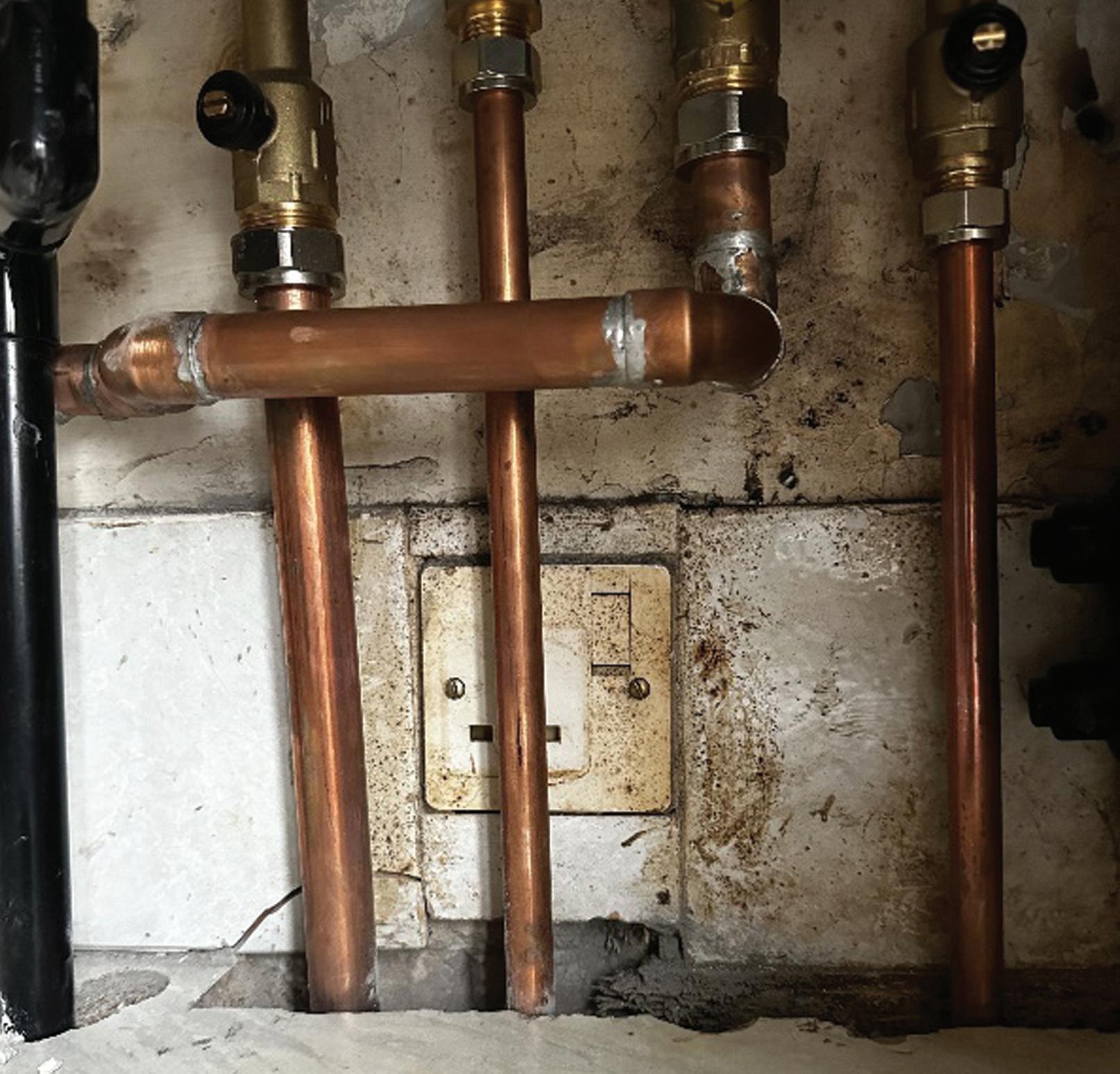
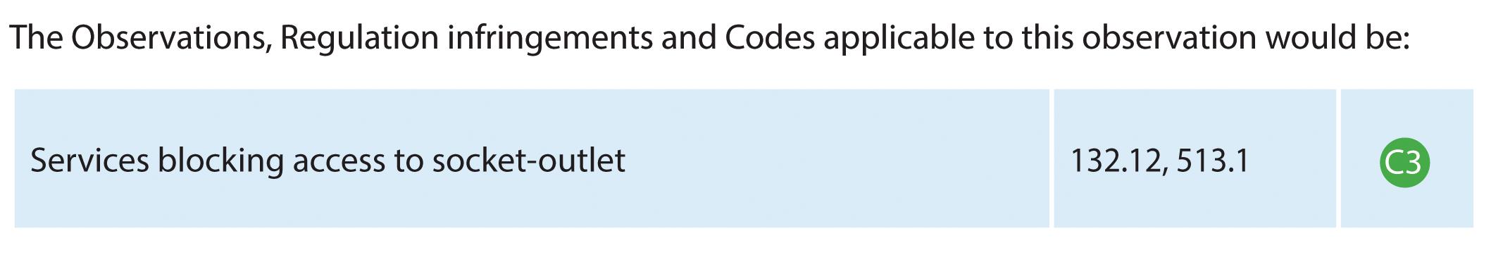
At times, it can seem to be the case that the electricians are seen as invisible to other trades, especially with our electrical accessories that could potentially be in their way
In this example, the plumber has changed or installed a new boiler or water system and has not considered the elec trical installation With the installation of the new pipework , the socket- outlet needed to be installed into a new accessible position, but now we have a situation where the socket- outlet can no longer be used
This could also cause a fur ther issue when conducting periodic inspection and testing, where this socket- outlet could not be inspected, or any form of testing be per formed
Therefore, the classification code would be a C3, Improvement required, due to the lack of access to the socket- outlet.


Updated for BS 7671:2018+A2:2022, NAPIT ’s EICR Codebreakers publication is purpose -written to aid contractors, inspectors and clients, and now includes updates to align with Amendment 2 of the IE T 18th Edition Wiring Regulations The book is the per fect technical aid for electrical professionals and their customers.


Need help with cracking those all-impor tant EICR codes? Ever y month the technical team at NAPIT will be studying your latest ‘Caught on Camera’ photos and offering advice on the next steps, should you find a similar installation. If you want the team at NAPIT to help crack your codes then send your pic tures through to us at: pe@hamer ville.co.uk


When accessories are installed as par t of the electrical installation, they become an integral par t of the wiring system and must comply with all aspects of BS 7671 and Building Regulations.
In this instance there has been no provision of a back box to enclose the live par ts or conductors and the circuit protective conductor (cpc) continuity has not been maintained throughout the circuit
I t is often overlooked that the cpc is required to be installed and terminated to each point of the wiring and each accessor y. The only exception is for a lamp holder
Although this device is marked as a double insulated and does not require ear thing, the requirement is to terminate the cpc at this point
Failure to terminate the cpc ’s does not provide the continuity of protective conductor or any exposed- conductive -par ts that are par t of the circuit
The lack of an enclosure for an accessor y does not provide containment of live par ts and for any protection against potential spread of fire The lack of secure fixings for the accessor y also places strain on the connections with the potential to allow the live connections to become exposed
Therefore, the classification code would be a C2, Potentially Danger present – urgent remedial action required, due to the lack of cpc continuity


The A2:2022 18th Edition Codebreakers publication is priced at £22.00 (members) and £24.00 (non-members). It is available in both hard copy and digital versions * Price is VAT exempt and excludes postage and packaging.


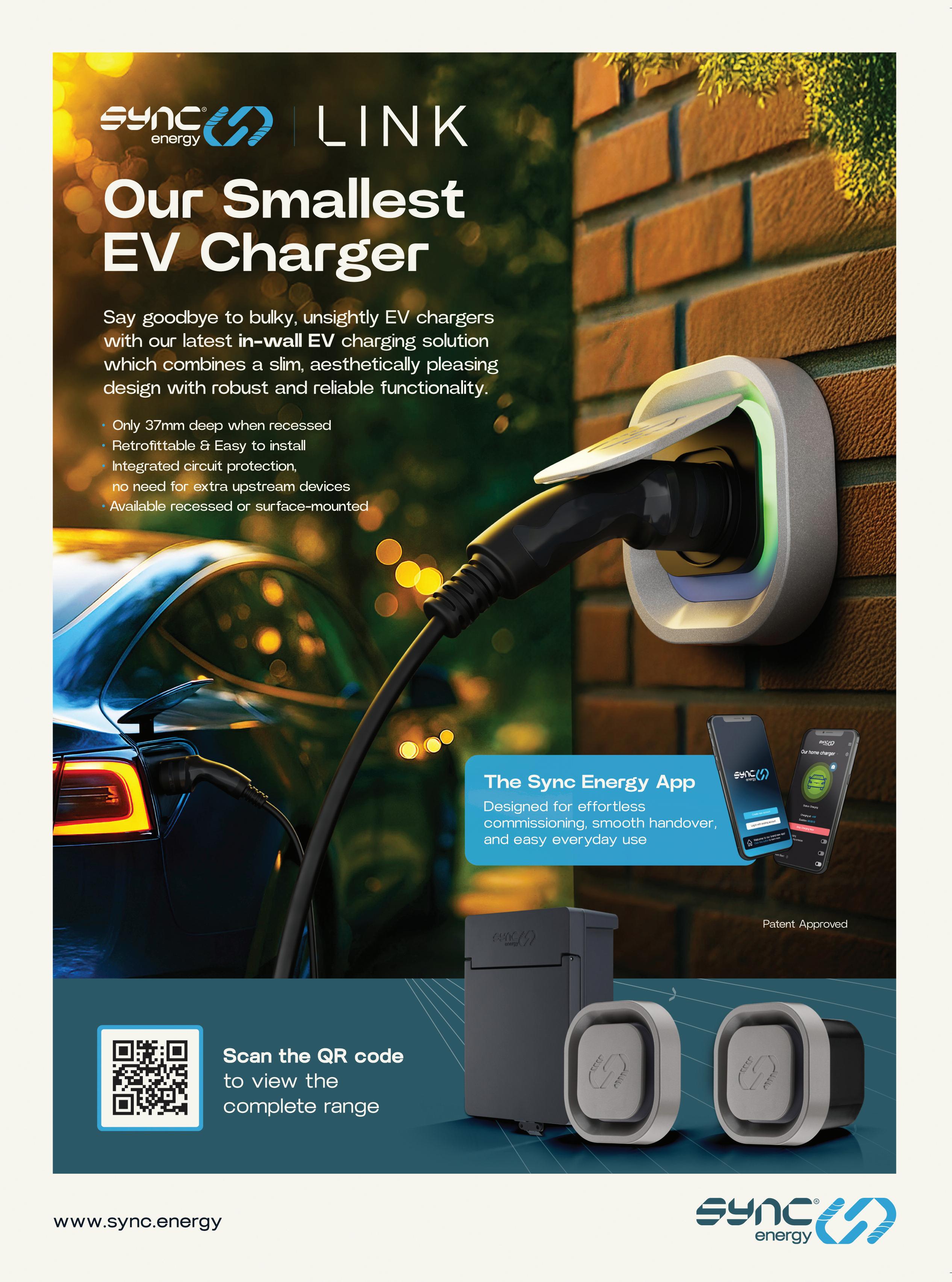

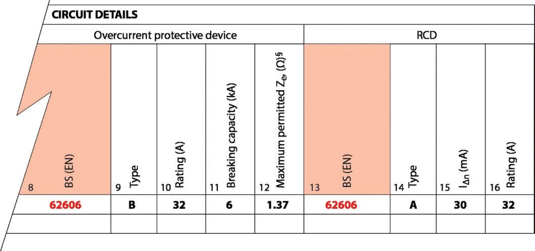
A number of protective devices are now available which perform more than one function, such as Residual Current operated Circuit-Breakers with integral Overcurrent protection (RCBO), and combination RCBO and Arc Fault Detection Devices (AFDD). The model ‘Schedule of circuit details’ in Appendix 6 of BS 7671 asks for a number of key functional characteristics of the various elements within the device to recorded. This article from the experts at NICEIC describes how these details can be recorded.
Switchgear manufacturers have developed several protective device products for use in distribution boards and consumer units which contain multiple functionalities, including those of a:
● Circuit-breaker
● Residual Current Device (RCD)
● Arc fault detection device (AFDD).
Combining multiple functions into a single device provides a benefit that smaller distribution boards having fewer ‘ways’ may be installed than would be the case if devices providing only a single function were installed. It also allows the required or desired protection to be more easily applied to the circuit(s) the designer intended However, enquiries received by the
NICEIC field and helpline teams indicate that the use of such combination protective devices is causing some confusion in respect of the information that must be recorded on the Schedule of Circuit Details which form part of both an Electrical Installation Certificate (EIC) and Electrical Installation Condition Report (EICR).
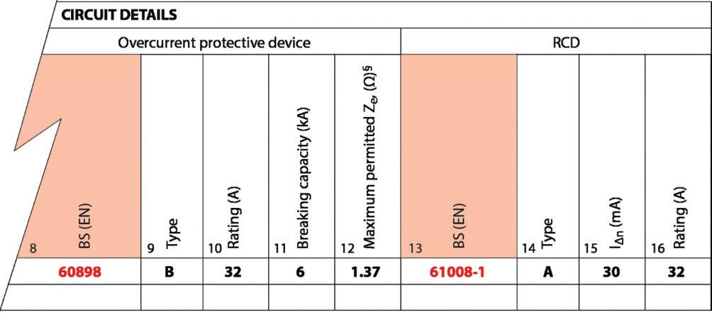
As can be seen in the extract reproduced in Fig 1, the new Schedule of Circuit Details introduced in Amendment 2 (AMD2) published in 2022 requires information relating to both the overcurrent protective device and any installed RCD to be recorded.
Completing the ‘BS (EN)’ columns (numbered 8 and 13 respectively in the BS 7671 model form) is a straightforward
matter where the overcurrent protective device and RCD are separate, standalone devices
However, what’s less clear is how these fields should be completed where the circuit-breaker and RCD elements are combined in an RCBO or even more so when such functionality is integrated in an AFDD.
Where separate overcurrent protective device and RCD are installed
Where a circuit is protected by a separate circuit-breaker and RCD, it is clear that ‘60898’ should be entered in column 8 to identify the circuit-breaker and ‘61008-1’ should be entered in column 13 to identify the RCCB (an RCCB being the specific form of RCD used in this instance) (Fig 2)
Where an RCBO is installed
Clause 1 (Scope) of BS EN 61009-1 states that ‘This standard applies to devices performing simultaneously the function of detection of the residual current, of comparison of the value of this current with the residual operating value and of opening of the protected circuit when the residual current exceeds this value, and also of performing the function of making, carrying and breaking overcurrents under specified conditions ’
Note 1 to this clause clarifies that content of the standard relating to residual current conditions is based on IEC 61008-1 while the content relating to protection against overcurrents is based on IEC 60898-1
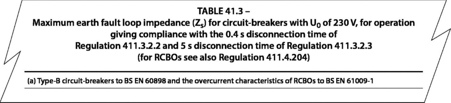
Table 41 3 of BS 7671 (Maximum earth fault loop impedance (Zs) for circuit-breakers with U0 of 230 V, for operation giving compliance with the 0 4 s disconnection time of Regulation 411 3 2 2 and 5 s disconnection time of Regulation 411 3 2 3) specifically references in the descriptors to Parts (a), (b) and (c) thereof that the data within the table is applicable to both circuit-breakers to BS EN 60898 and to the overcurrent characteristics of RCBOs to BS EN 61009-1 (Fig 3)
This clarifies that the device providing the overcurrent protection is the
BS EN 61009-1 RCBO and not a circuit-breaker to BS EN 60898
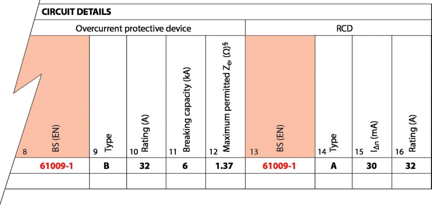
It would therefore be incorrect, and confusing, to those inspecting the installation at a later date if ‘60898’ was recorded in column 8, as there is not a BS EN 60898 circuit-breaker protecting the circuit; the installed device is an RCBO to BS EN 61009-1
Where the circuit is protected by an RCBO, ‘61009-1’ should be recorded in both column 8 and column 13 (Fig 4)
Where an AFDD with integral overcurrent device and/or RCD functionality is installed
The same logic should also be applied when considering an AFDD to BS EN 62606 incorporating an overcurrent protective device and/or an RCD.
Clause 1 (Scope) of BS EN 62606 General requirements for arc fault detection devices states that ‘The integrated protection device is either a circuit-breaker in accordance with IEC 60898-1 or an RCD in accordance with IEC 61008-1, IEC 61009-1 or IEC 62423. ’ In order to determine which of these standards is applicable to a particular device reference should be made to the manufacturer’s data for the AFDD being installed
Where an AFDD incorporating overcurrent protective device and a separate RCD are installed
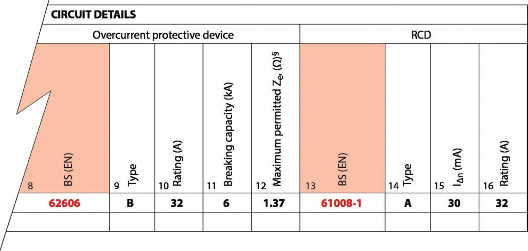
The device providing the overcurrent protection is the BS EN 62606 AFDD and not a circuit-breaker to BS EN 60898
As was the case where an RCBO is installed, it would be incorrect, and confusing, to those inspecting the installation at a later date if ‘60898’ was recorded in column 8, as there is not a BS EN 60898 circuit-breaker protecting the circuit; the installed device is an AFDD to BS EN 62606 (Fig 5)
As there is a separate RCD installed, the following should be recorded in column 13:
● ‘61008-1’ for an RCCB
Where an AFDD incorporating both overcurrent protection and RCD functionality is installed
Where this type of device is installed:
● The overcurrent protection is provided by the BS EN 62606 AFDD and not a circuit-breaker to BS EN 60898 It would be incorrect, and confusing, to those inspecting the installation at a later date if ‘60898’ was recorded in column 8.
● The RCD functionality is provided by the BS EN 62606 AFDD and not an RCD in accordance with IEC 61008-1, IEC 61009-1 or IEC 62423 Again, it would be incorrect, and confusing, to those inspecting the installation at a later date if ‘61008-1’ was recorded in column 13 (Fig 6)
In order to provide the correct information required for the identification of the functional characteristics of protective devices providing more than one type of protection, whether overcurrent, residual current and/or arc fault current, it is necessary to refer to the relevant product standard to which the installed product conforms. A summary of this information is provided in Table 1
Providing the information in this manner is not only a correct reflection of the installed equipment but will also aid those carrying out alterations and/or additions or periodic inspection and testing at a later date to correctly identify the installed protective devices for the circuits of the installation.


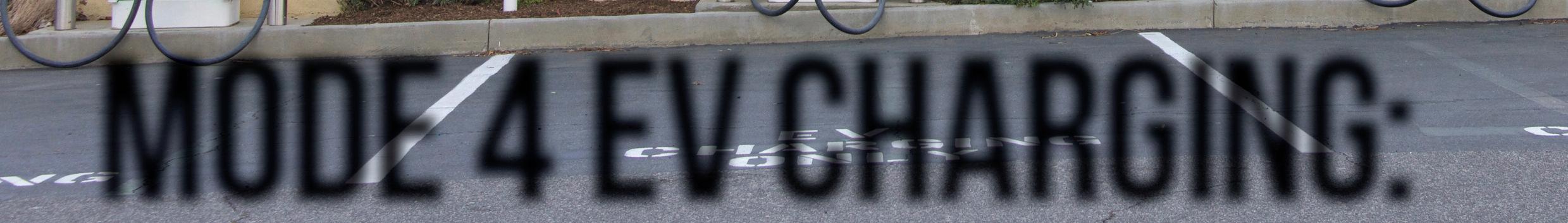
f you’re involved in regular installation of DC EV chargers, you’ll already be familiar with the significant differences between individual manufacturers’ performance characteristics and the impact on the supply-side equipment e.g. transient inrush current, harmonic distortion, leakage current, and associated RCD selection
Mode 4 guidance
It is not possible to give standardised recommendations for RCDs associated with Mode 4 chargers. But why?
Whilst there has been agreement for Mode 3 charging standards in Europe, with the publication of ENIEC 61851-1 2017, and the associated changes in section 722 BS 7671 2018, that is not the case with Mode 4 charging standards which are still coalescing.
DC charger design is far more complex due to the safety issues associated with high DC voltage/current This is reflected in the time taken to agree on a revision of BS ENIEC 61851-23 2014 – the current designated standard for DC charging, quoted in BS 7671.
For example, this early standard gives general design requirements but is light on standardised test methods for checking conformity This results in a wide variation in basic standardised performance characteristics between individual manufactures claiming compliance with a designated standard.
The current edition of BS 7671 (Oct 24) Clause 722 531 3 101 relating to RCD selection Note 2 states that: supplies using DC vehicle connectors to the BS EN 62196 series are under consideration.
Electrical safety design characteristics (the guts of the charger) may depend on the DC interface charging technology adopted by the vehicle manufacturer e g CHAdeMO (Japanese), GB/T (China), CCS 1 & 2 (North America & Europe), and Tesla (proprietary design NACS – based on North American standards).
Later versions of Tesla DC chargers were supplied with CCS 2 interface (compatibility with European EVs), but still NA electrical design standards
Use the basic principles of BS 6761 (clause 133.1, 134.1.1, and 531.3.3) to select appropriate RCDs, based on the individual chargepoint manufacturer’s characteristics and installation recommendations e g note minimum RCD characteristic requirements at the quotation stage *
* Clause 642 (Inspection): Refer to as an aid-memoire during installation planning/equipment verification.
Mode 4 chargers – general points
RCDs installed on the AC supply feeding the charger does not provide protection on the DC side of the charger. Electric shock and fault protection on the DC side is the responsibility of the chargepoint manufacturer: Conformity with the essential safety requirements is indicated by CE/UKCA Marking – see Clause 642 Refer to the chargepoint manufacturer’s installation instructions.
Inrush/transient currents

Depending on design and technology ed, equipment containing high ectifiers/inverters can produce ant transients during operation with the equipment manufacturer –may require transient resistant s, to prevent unwanted tripping necessary equipment downtime
This is the current that flows to earth during normal operation Leakage current values are specific to the manufacturer’s design and will vary as a function of the individual chargepoint harmonics, produced during various stages of charging and the supply quality (existing harmonic content)
The existing standard BS ENIEC 61851-23 sets minimum protective conductor requirements for Class 1 equipment, where touch currents exceed 3 5 mA Follow the manufacturer’s recommendations if they exceed the requirements of BS 7671 543 1 - 543 7
Unexplained RCD tripping may be the result of insufficient safety margin between the operational leakage current and the RCD sensitivity; note recommendations in 531 3 2 (ii)
Until recommendations are included in BS 7671-722, unless otherwise stated by the chargepoint manufacturer, only Type B RCDs (RCCB, RCBO, CBR) should be used upstream of Mode 4 chargepoints – see 531 3 3 (iv)
With any innovative technology the “state of the art” is an important concept to consider about the existing requirements of BS 7671 and installation advice provided by the equipment manufacturer Ask before acting and keep in mind the requirements of clause 133 1, 134 1 1 and 531 3 3

Steve Humphreys, Technical Commercial Manager
at
NAPIT, provides a guide on how to fix PV arrays to on-roof solar photovoltaics systems.
In this article, we will look at a simplified wind uplift calculation to determine how any fixings would be required for the array mounting system
One of the most important aspects of installing a solar photovoltaic (PV) system is the mounting of the PV array on the roof Fortunately, most modern domestic roofs can comfortably withstand the weight of a solar panel array The weight of a typical domestic array will be lower than the weight carrying capacity of the average roof
However, all roof structures should still be assessed by a professional If it can be seen that the roof components are in poor condition or that the property is very old, then guidance should be sought from a roofing professional or structural engineer

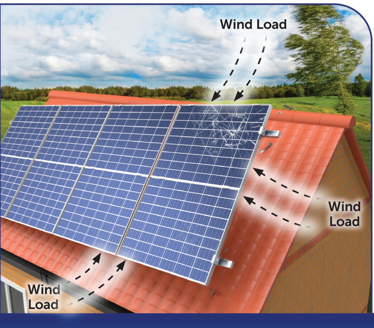
Wind load is more of a concern when mounting a PV array on a roof It can cause uplift when it makes its way between the roof and the solar panels, causing the panels to rise or break free, see Fig 1
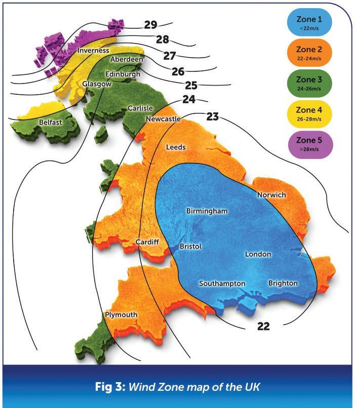
Wind loads can vary significantly across the UK and is influenced by factors such as altitude, building height and local topography.
In areas where the panels are close to the roof edge, additional consideration should be given to the fixing points as the wind uplift will be greater there
There are various software applications available that can be
used to determine how many fixings are required, however, it’s important to understand the basis of wind uplift calculations
Wind Force (uplift) = Qp x A x Cp x SF
Where:
Qp is the peak velocity pressure
A is the area of module or array
Cp is the pressure coefficient
SF is the safety factor
Peak velocity pressure (Qp)
Peak velocity pressure is the maximum wind pressure that is to be expected at a particular location over a 50-year period.
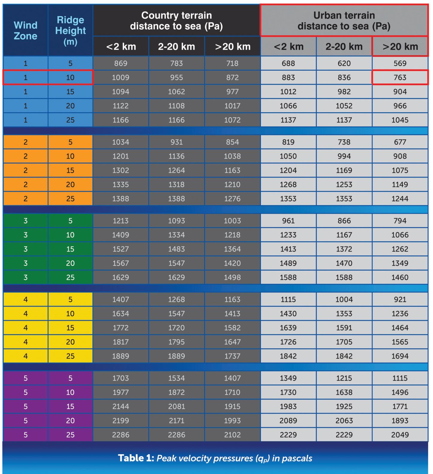
The procedure for calculating peak velocity pressure is contained within BS EN 1991 Eurocode 1: Actions on structures, Parts 1-4: General actions - Wind Actions In order to determine the peak velocity pressure, we need to consider the following site-specific factors:
● Basic mean wind velocity (this can vary according to location and is taken from a map of the UK)
● Altitude correction factor (this accounts for the height above sea level)
● Reference height (the height of structure above ground level)
● Local terrain (the terrain type i e sea, town or country)
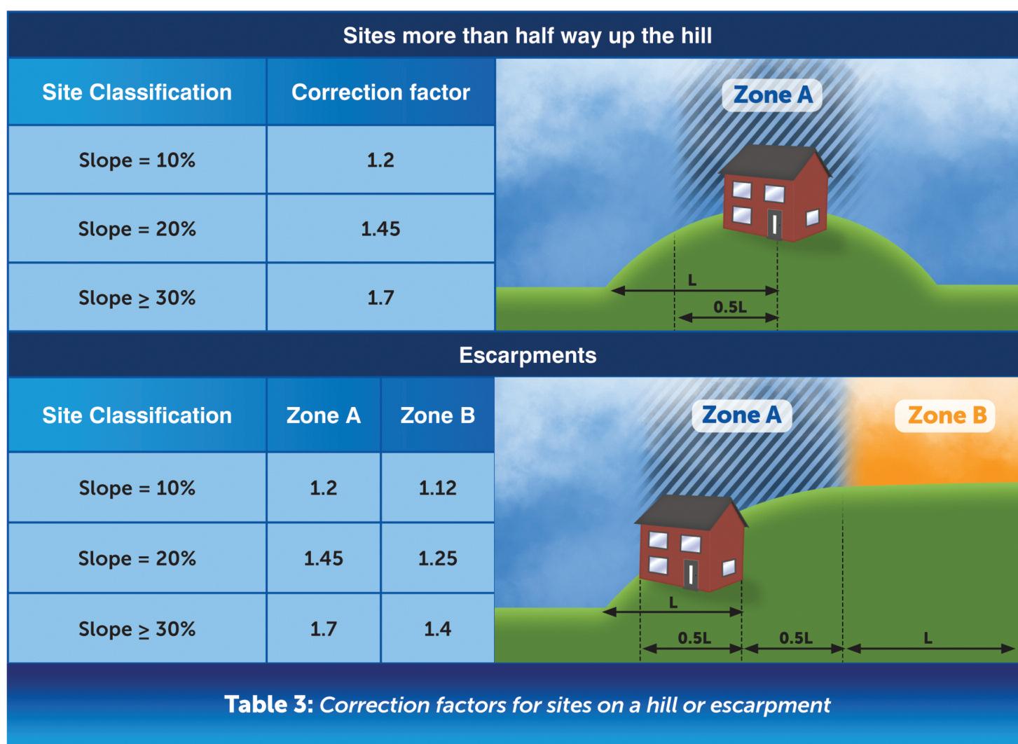
● Topography (this adds a correction factor where the site is on a hill or escarpment)
● Distance from the sea
Area of module or array (A)
This is quite simple to work out as the array size will be the metre square (m2) of one panel times the number of panels
Pressure coefficient (Cp)
The pressure coefficient is the external wind-induced pressure acting on the outside of the building, including the PV array.
“The pressure coefficient is the external wind-induced pressure acting on the outside of the building, including the PV array.”
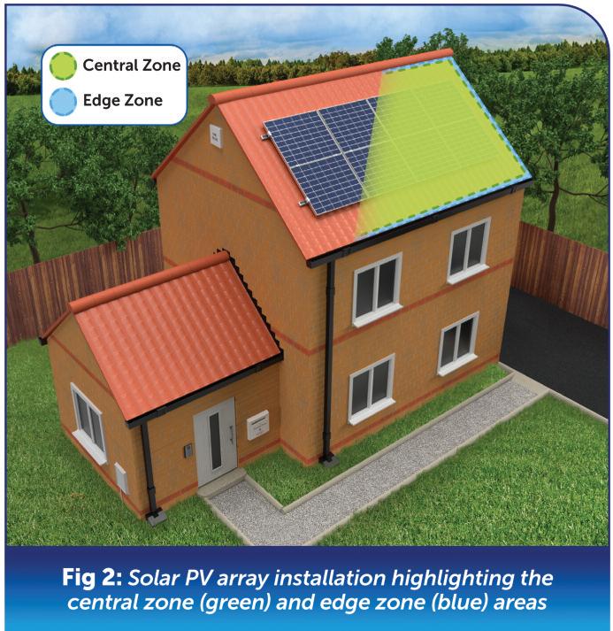
In general terms, for PV arrays that are installed in the ‘central zone’ of a Duopitch roof at an angle of 30˚ and has a gap of less than 200 mm from the underside of the array to the roof surface, a pressure coefficient of -0.5 can be used In contrast, for PV arrays installed in the ‘edge zone’ of a similar roof, a pressure coefficient of -0 6 is used, as displayed in Fig 2
Safety Factor (SF)
A safety factor should be applied to all
wind load calculations For PV systems mounted on roofs, a safety factor of 1 35 can be used
Let us now look at a worked example assuming the following scenario:
● An on-roof PV array installed in the ‘central zone’ of the roof
● The area of the array is 20 m2
● The array mounting is a rail and fixing bracket system with each fixing bracket having a rated capacity of 500 N
● The site is located in Birmingham, not on a hill, in urban terrain and is more than 20 km from the sea
● The altitude of the site (height above sea level) is 100 m
● The height of the building (from ground level to ridge height) is 10 m
First, we must determine the peak velocity pressure using a wind zone map for the UK, shown in Fig 3 Birmingham is located in Wind Zone 1, which has a value of 22 metres per second (m/s).
Our next step will be to determine the peak velocity pressure in the PV array by using the information provided in Table 1, along with the assumptions for the PV array
Peak velocity pressure (Qp) = 763 pascal (Pa)
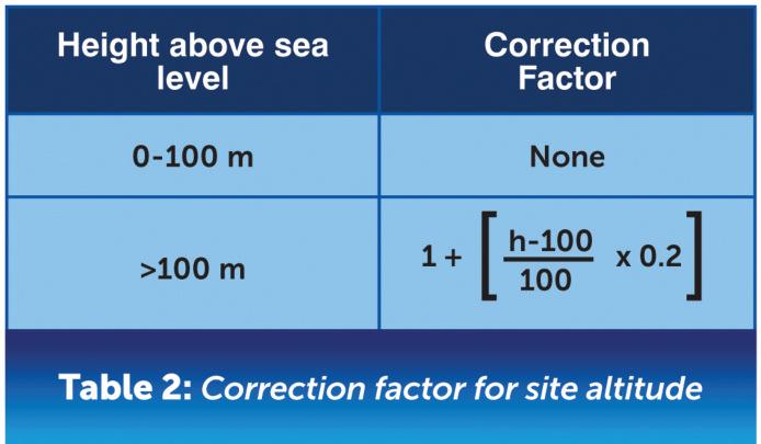
The site altitude is not applicable to this e x a m p l e a s t h e s i t e i s 1 0 0 m e t r e s a b o v e sea level
In the case of sites located over 100 metres above sea level, the formula shown in Table 2 should be used to calculate the correction factor
To p o g r a p h y i s a l s o n o t a p p l i c a b l e i n t h i s example
If the site is on a hill or escarpment, the correction factor derived is shown in Table 3.
Let us now add all our values to the original formula:
Wind force (uplift) = Qp x A x Cp x SF
Qp is 763 Pa
A is 20 m2
Cp is -0 5 SF is 1.35
Therefore:
763 x 20 x -0.5 x 1.35 = 10,300.5 N or 10.30 kN
Finally, we need to establish the number of fixing brackets needed for the imposed total wind uplift force
● Total wind (uplift) force acting on array = 10,300.5 N
“Manufacturer’s instructions will give a maximum spacing between fixings and a maximum cantilever for the end fixings.”
● Each fixing brackets rated capacity = 500 N
Total wind (uplift) force acting on array/each fixing bracket having a rated capacity
10,300.5/500 = 20.6 so therefore at least 21 fixing brackets would be required
Conclusion
You can see from the wind uplift calculation, determining how many fixing brackets are needed for an on-roof mounted PV array can be complex. As mentioned earlier, software applications may be suitable when designing the PV array and mounting system
It’s also worth pointing out that the roof structure and the distance between the rafters will often dictate the location and number of fixing brackets used.
Manufacturer’s instructions will also play a large part in the spacing of fixing brackets
Manufacturer’s instructions will give a maximum spacing between fixings and a maximum cantilever for the end fixings Whatever method is used, it’s essential that the correct amount of fixings are used to prevent panels, the whole array, or the mounting system from breaking free
All of this information and more is available from the latest NAPIT publication: Practical Guide: Solar Photovoltaic Systems, available for pre-order at NAPIT Direct
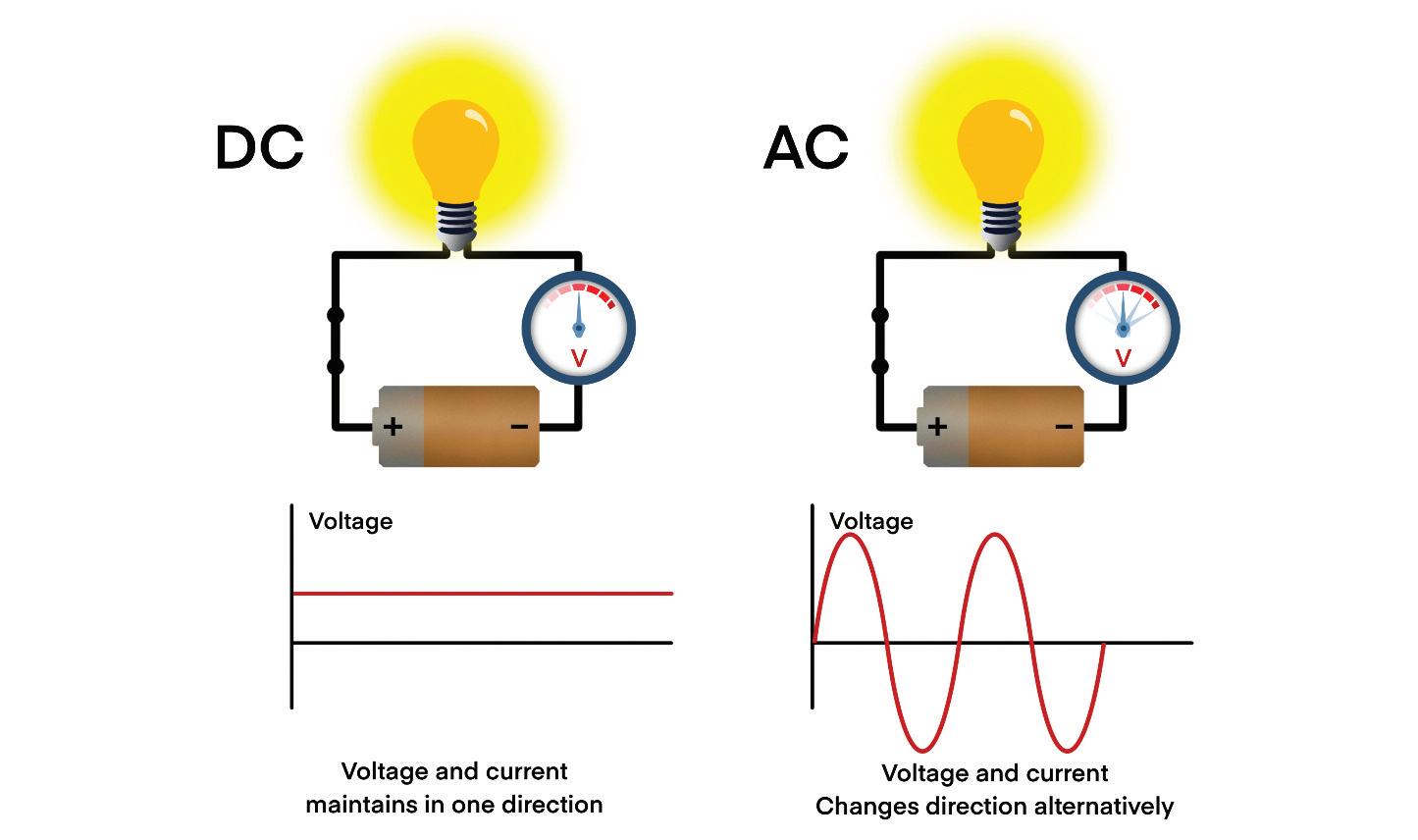
The majority of electricians, whilst familiar with the principles of direct current, are lacking in actual experience of working with DC circuits This is largely due to public low voltage supplies being 230/400 V AC
However, with the proliferation of photovoltaic systems, rectifiers, wind turbines, electrical energy storage systems and electric vehicle chargers, which utilise direct current, perhaps it’s time to brush up on your knowledge so that you can be safe at work and not fall foul of Regulation 16 of the Electricity at Work Regulations 1989 which states:
“No person shall be engaged in any work activity where technical knowledge or experience is necessary to prevent danger or, where appropriate, injury, unless he possesses such knowledge or experience, or is under such degree of supervision as may be appropriate having regard to the nature of the work ”
I hope this article will provide you with some food for thought and encourage you to explore the topic further
Isolation and earthing considerations DC supplies may or may not be earthed If you intend to operate an earthed DC system independent of the AC supply you must ensure the means of earthing continues to function by meeting the requirements of BS 7671 551 Low Voltage Generating Sets. Regardless of earthing, where DC supplies operate in the absence of an AC supply, steps must be taken to ensure that energised parts of the system can be isolated and that users, maintenance staff and emergency workers are able to safely isolate the DC system.
Alternating current rises and falls meaning that the current is zero Amps 100 times a second for a 50 Hz supply and subsequently arcs are more quickly extinguished. You can sometimes see an arc when switching a load (such as an immersion heater) as a faint flash of light through the side of the switch
Direct current does not pass through zero and can draw a significant arc for longer periods of time over larger distances than similar voltages of alternating current
When selecting switchgear it is essential that DC rated equipment is selected since the mechanisms are designed to operate more quickly and may have larger more robust parts. Often AC and DC switchgear appears to be the same product but closer
“Both AC and DC supplies have the capacity to kill, so it’s important to treat it with the respect it deserves.”
inspection will reveal that DC components are rated for lower voltages and current Switches are often linked-out too, effectively doubling the switch gap by utilising two switches in series
The removal of fuses and disconnection of plug and socket connectors can result in damage Loads should be removed and proved dead before attempting to disconnect.
A good DC clamp meter (preferably one with a flexible loop to permit access
in tight areas) will be useful With some equipment you may need to leave time for capacitors to become safe or discharge them in line with manufacturer instructions.
When selecting protective devices it’s important to confirm if the British Standard of the device selected covers DC and, where it can be utilised in AC and DC systems, take note of the voltage range which will be lower for DC than AC
Table 51 of BS 7671 provides a list of colours used in DC systems but it is recommended to label DC cables throughout their length and segregate them from AC cables when run in containment.
Electrolytic corrosion is a process which occurs when metals in building structures are in contact with the ground
When current flows in one direction it can cause the metal work to be oxidised (corroded) which may lead to premature failure It is often hidden, given that the reaction is in the ground
Electricians working in the rail sector will be all too familiar with this issue where large DC currents are present, but the rest of us might be less so.
Both AC and DC supplies have the capacity to kill so it’s important to treat it with the respect it deserves
If you’re unfamiliar with DC supplies a good starting point to help you with understanding more about the subject would be the IET’s Technical Briefing –Practical considerations for d c installations – available for free through the link below
LEARN MORE ABOUT ARENA TRAINING’S COURSES AT:
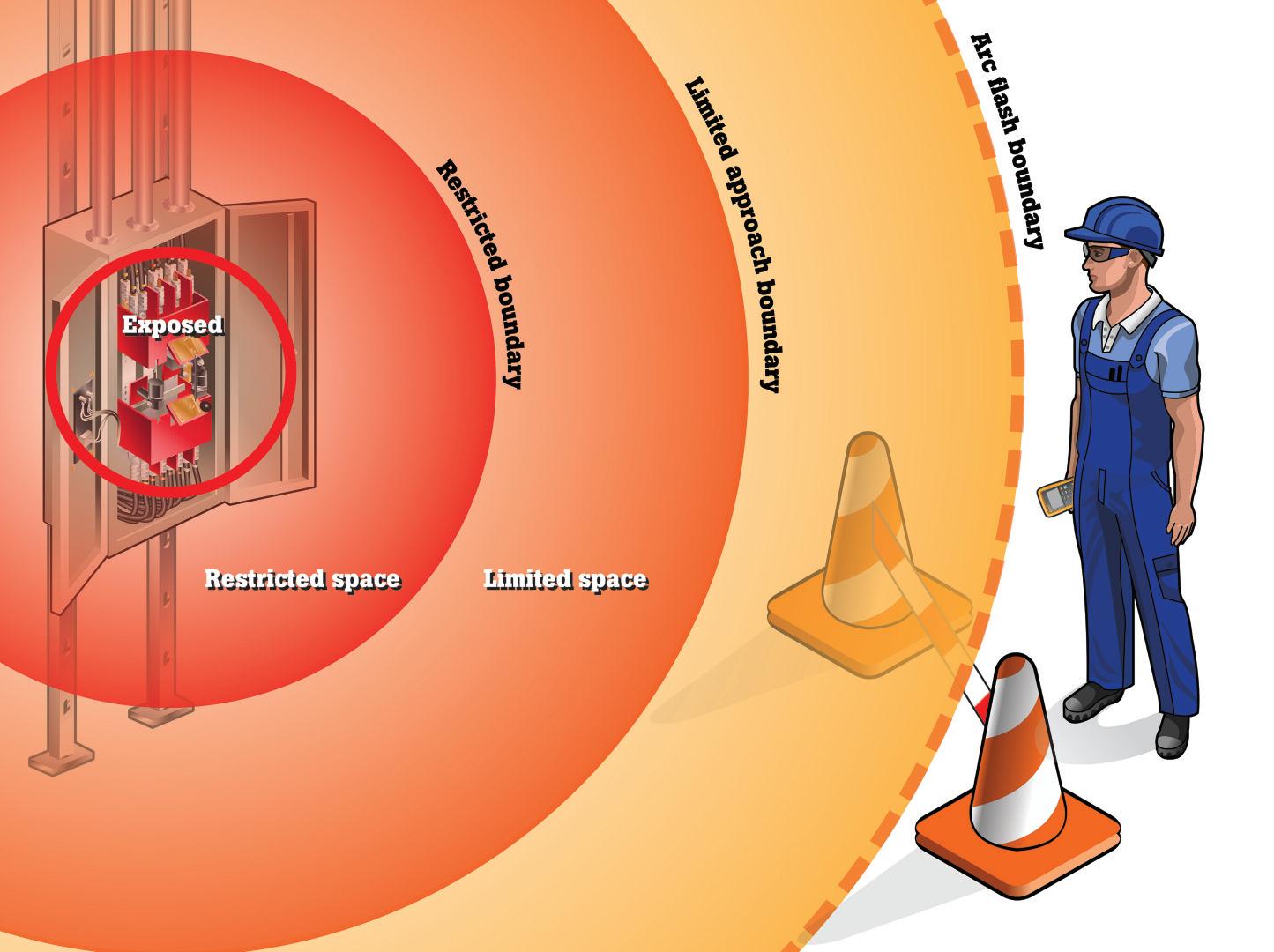
In this article the experts at Fluke discuss the importance of the arc flash boundary and the ways in which professionals can better ensure that arc flash incidents are kept to a minimum.
The arc flash boundary is the minimum “safe” distance from exposed energised conductors or circuit parts that has the potential for an arc flash.
Arc fault incidents happen daily around the world As such, you should take the proper steps to ensure your safety before taking any measurements, especially on energised equipment Knowing where the arc flash boundaries are is vitally important, so keep these top safety measures in mind
The National Fire Protection Association (NFPA) recommends defining three boundaries to minimise risk of electrical injuries Part of NFPA 70E highlights what each boundary is and how to determine where to place it. It breaks down to basically be, as you move closer to the exposed and live equipment, the more training and higher levels of personal protective equipment (PPE) you need
Arc flash boundary
The arc flash boundary, or restricted
approach boundary, changes depending on the potential arc flash hazard
The arc flash boundary is calculated to 1 2 calories/cm2 of incident energy That’s the distance where a worker without appropriate PPE would receive second-degree burns
Sometimes this boundary is the furthest one from the exposed equipment, other times the limited approach boundary is the furthest out When the arc flash boundary is the furthest away, it becomes the line no one should pass without training and PPE If the limited approach boundary is further out, then that should be treated as the line no one should pass without training and PPE
approach boundary
Moving toward the energised and exposed equipment, you’ll find the limited approach boundary Within this boundary, it is still possible to be exposed to a shock hazard Appropriate PPE should be worn by qualified workers in the limited space (space between the limited approach
boundary and the restricted boundary) Non-qualified workers should stay outside of this boundary unless wearing proper PPE and being escorted by a worker with specialised training.
Restricted boundary
The area closest to the live, exposed equipment is within the restricted boundary In order to pass this boundary, you must be a qualified worker with the proper training and PPE. If you need to perform work on the energised equipment, you may also need a work permit and documentation
Equipment considerations
Work on de-energised equipment
It’s the only way to eliminate hazards
Follow the lockout/tagout procedures and, whenever possible, take measurements while the system is de-energised Be sure to test for absence of voltage before conducting any tests without the necessary PPE. Until absence of voltage
testing proves the circuits are dead, they must be considered energised
Inspect equipment regularly
You can catch some wear and tear before it becomes a problem by regularly inspecting your equipment
Knowing the history of your equipment and what a normal reading looks like can help you identify abnormalities Gather baseline readings by inspecting critical components like electrical connections, insulation and circuit breakers
Checking the equipment regularly using condition monitoring tools or IR windows can also help you catch an issue before it’s too far down the road Knowing the machine’s health history means you can take any necessary corrective actions at the right time
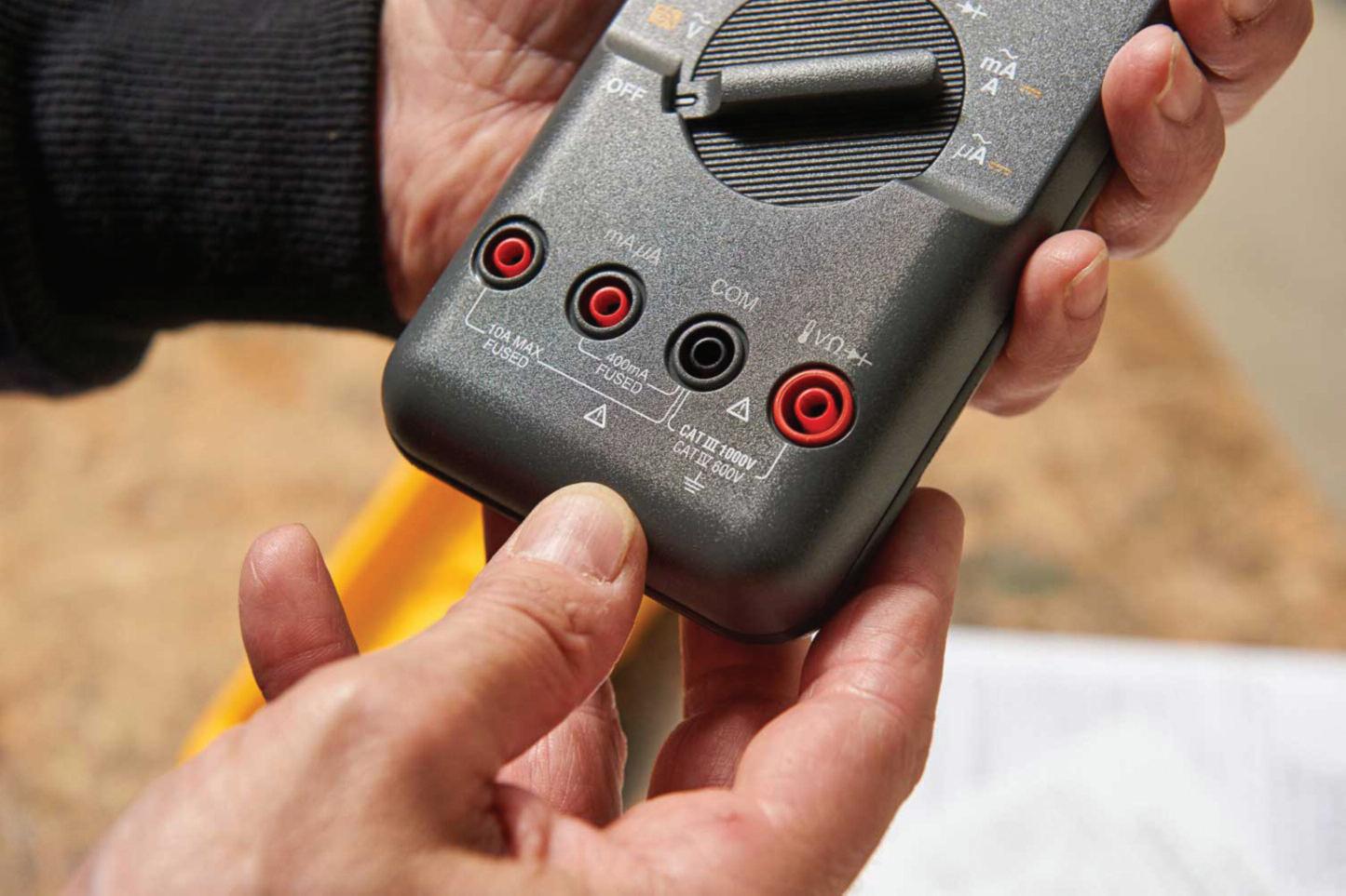
Test instruments must go through standardised testing in order to meet safety requirements The CAT and voltage ratings listed on the test instrument and any accessories also need to match or exceed the electrical environment where you will use them
Look for tools that meet IEC standards with an independent lab testing verifying
it The lab’s symbol on the tool means an independent testing agency has checked the safety claims and CAT ratings and the test instrument passed
Test tool condition
Be sure you’re not using tools or accessories that are outdated or defective While your digital multimeter should last for a long time, it can still break or wear down eventually Accessories and smaller test instruments should be replaced more regularly Test leads, temperature probes and fuses, for example, won’t work accurately forever
Inspect any test instruments before you use them Look for any extra wear and tear, cracks, fraying or insulation showing. Make sure any connections are secure And, use the live-dead-live testing method to ensure your instruments are working properly before and after taking a measurement The live-dead-live testing method requires testing the functionality of your equipment on a known voltage source before and after taking a measurement
Stay out of the arc flash boundary
There’s no need to put yourself in an arc blast zone if you don’t need to be. Products like remote display, wireless and
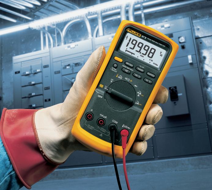
non-contact tools can help put you further away from danger or let you take readings on an energised part without making contact They include:
● Non-contact voltage detectors or electrical testers
● Non-contact infrared thermometers
● Infrared cameras
● Remote display multimeters
Arc flash vs arc blast
Following these safety guidelines will help you stay safe in the event of an arc fault, but it’s important to also understand the ‘how’ and ‘what’ How is an arc fault caused and what is the difference between arc flash and arc blast?
Check out the link at the bottom of the page to get the full explanation
CLAIM YOUR CERTIFICATE!
SCAN THE QR CODE TO CLAIM YOUR CPD CREDIT FOR THIS SECTION OR VISIT: WWW.RDR.LINK/ EBJ015

VISIT THE ARC FLASH VS ARC BLAST EXPLANATION PAGE AT: WWW.RDR.LINK/EBJ016
GET MORE DETAILS ABOUT FLUKE’S RANGE OF TEST EQUIPMENT AT: WWW.RDR.LINK/EBJ017

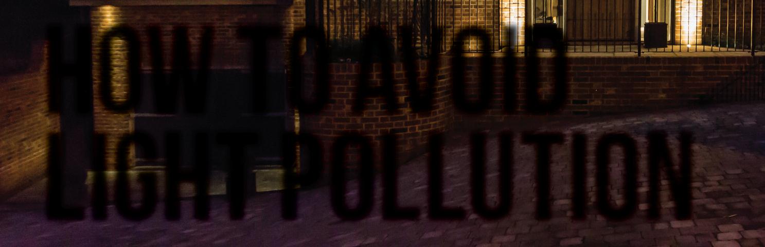
While we need good outdoor lighting for safety, for work or to simply enjoy an outdoor meal on a warm summer’s evening, light pollution can be a problem As such, if you’re installing external lighting, you must ensure you get it right to meet most councils’ DarkSky initiatives
One thing you should always do is to take step back from the project that you’re lighting and consider the impact it will have on the surrounding areas and the darkness of the night sky The opening question you should always ask is whether your customer actually needs the lighting in the first place.
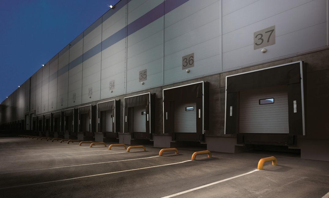
Direct the light
If the answer is “yes”, you should only light the area that needs it This means that the luminaire should have hoods or shielding so that you can target its direction to ensure there is no light spillage causing glare Think about the beam angle that you’re using and what you’re lighting
Where you can use wall lights, don’t mount them too high above the area you’re lighting as this will give a steep tilt angle that can cause unwanted light pollution If you do use uplights ensure that you direct the light and contain it to the area that you’re lighting Luminaires with asymmetric beams will focus the light in one direction, making it easier to achieve this.

Mitchell Waite, Product Manager at Collingwood Lighting, looks at how to nstall external lighting to avoid light pollution and meet many councils’ DarkSky policies.

Avoid upward light spill
The glow that we see at night from artificial lighting is due to unwanted light spilling upwards and away from its intended area
Where you’re using a wall light always

check its upward light output ratio (ULOR), which is the percentage of light that it emits above the horizontal plane For DarkSky approval it should have a ULOR of less than 0 5% or 50 lumens
Well-designed fittings will have high quality optics so that you can accurately direct the light where you need it, whether that’s downwards or focussed on the object that you’re lighting with minimal or no spillage
The DarkSky initiative also specifies that you should keep lux levels low where possible and to not use overly bright lights The illuminance needed will depend on what the lighting is for, and you will need to refer to appropriate standards for each situation.
In addition to controlling where the light goes, your customer should only have it on when they really need it And, on occasions when usage is low, it should be dimmed to reduce the light and save energy.
Implementing control scenarios is far simpler for LED lighting than, for example, metal halide lamps that are in many older installations While the former are easily dimmed, the latter can only dim down to 50% of their rated power. In addition, LED lighting will switch on and off immediately in response to timers, or PIR sensors, whereas metal halide sources are slow to turn on
The correlated colour temperature (CCT) also matters. DarkSky requirements are for a CCT of 3000K or warmer because this is less likely to scatter in the atmosphere than higher colour temperatures that have short-wavelength ‘blueish’ light
This is particularly important for nocturnal animals and insects. If, for example, bats are known or suspected to be in the area then the amount of upward light spillage, particularly the blue light content of higher CCT values, can affect their circadian rhythms
In general, you should assess how much
light the fitting produces relative to the amount needed for the task LED lighting produces more lumens per watt than other sources, so they’re more energy efficient Some are more efficient than others so it’s worth checking the lumen output of a fitting rather than just its wattage LED luminaires also have a long life, so they will not need replacing as often and some have replaceable parts so your customer will not always need to install a new fitting LED lighting provides a sustainable option and, if you pick the right fittings, they’ll enable you to meet the DarkSky commitments of many local councils
In conclusion, as the Institute of Lighting Professionals Guidance Note 1 for the reduction of obtrusive light states: make sure that you install ‘the right light in the right place at the right time, under the right control ’


The aim of this article from the experts at NICEIC is to look at overcurrent; and, in particular, short-circuit current, and how the requirements of BS 7671 are applied. The adiabatic equation given in regulations 434.5.2 and 543.1.3 will be introduced and used within a typical example to indicate its application within short-circuit current analysis.
The different types of current that can lead to an overcurrent occurring in a circuit are shown in the block diagram of Fig 1
Fault current
Fault-current consists of two types of fault, as shown in Fig 1 – earth faults and short-circuits
● Earth fault currents flow when there is fault between a live conductor and earth as shown in Fig 2a.
● A short-circuit current flows as a result of a fault between live conductors, for

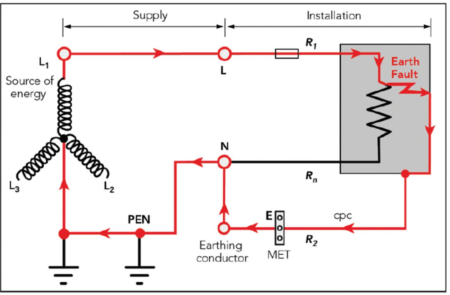
example line-to-line or line-to-neutral, as shown in Fig 2b
The anticipated fault current in such a circuit is called the prospective fault current (Ipf).
This article will only consider short-circuit currents between live conductors
Short-circuit current
The short-circuit loop is indicated by the red line in Fig 2b. Because of the higher
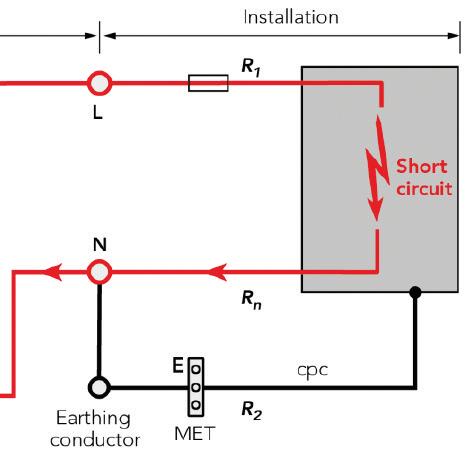
values of current typically associated with short-circuit conditions, care must be taken when selecting appropriate switchgear and protective devices
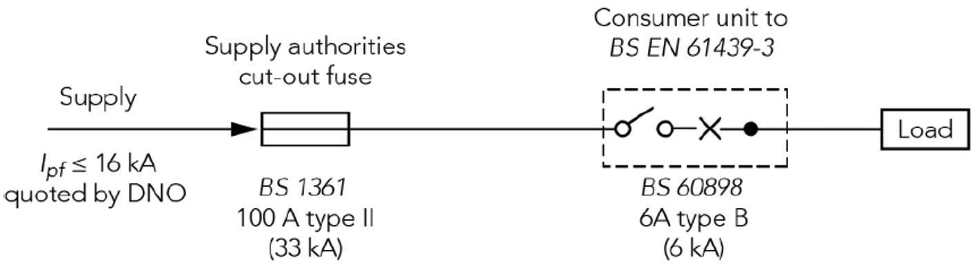
Regulation 434 5 1 requires that the rated short-circuit breaking capacity of each circuit protective device shall normally not be less than the maximum prospective fault current at the point at which the device is installed
However, a protective device having a lower breaking capacity is permitted if another protective device having the necessary rated short-circuit breaking capacity is installed on the supply side, as shown in Fig 3.
In this situation, the characteristics of the devices shall be co-ordinated so that the energy let-through of these devices does not exceed that which can be withstood, without damage, by the device(s) on the load side
In domestic (household) or similar premises, where a consumer unit to BS EN 61439-3 is used and the maximum prospective fault current
“The thermal withstand of the cable must be greater than or equal to the let-through energy of the protective device.”
declared by the distributor is 16 kA, it is not necessary to measure or calculate prospective fault current at the origin of the supply
This specific conditional short-circuit rating applies when using an upstream BS 88-3 (formerly BS 1361 type II) fuse-link with a maximum 16 kA PSCC at the service cut-out and not at the consumer unit
The relationship between the protective device and the cable
While regulation 434 5 1 typically relates to a protective device and its ability to withstand the effects of the maximum prospective fault current, regulation 434 5 2 is concerned with limiting the heat that will be added to the current-carrying conductor while such a fault exists
For any applicable disconnection time the maximum energy withstand of the cable must be equal to or greater than the let-through energy of the protective device Where this is not the case, there is the risk that under fault conditions the insulation may suffer thermal damage
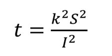
The time (t), in which a given fault current will raise the live conductors from the highest permissible temperature in normal duty to the limiting temperature, can, as an approximation, be calculated from the
adiabatic equation given in regulation 434.5.2:
It should be remembered that an earth fault has a maximum disconnection time of 5 s for TN systems (411 3 2 3) However, there is no such limitation on time given in regulation 434 5 2 for short-circuit currents Nevertheless, a check must be made to ensure that the protective device operates before the cable becomes damaged
Transposing the equation further to express the terms of the thermal relationship gives:
k2S2 = I2t
On one side is the thermal withstand of the cable k2S2 and on the other side is the let-through energy I2t of the protective device The maximum thermal withstand of the cable depends on its cross-sectional area S, and k, which is a factor that takes account of the material properties of conductors and insulation
As mentioned previously, the thermal withstand of the cable must be greater than or equal to the let-through energy of the protective device therefore, k2S2≥ I2t
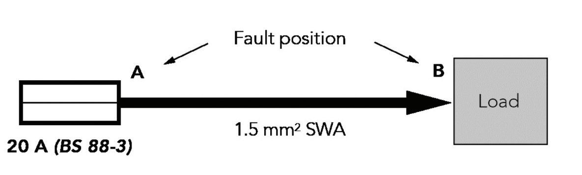
To illustrate the effects of a short-circuit occurring on a cable supplying a load, and referring to Fig 4, consider a fault occurring at position B, which due to a loose connection has some additional impedance If the total impedance of the line-neutral loop is 4 Ω, what effect will this have upon the circuit cable?
The circuit has been installed using a two-core 1.5 mm2 steel-wire armoured cable having copper conductors with 70°C thermoplastic insulation It is protected by a BS 88-3 fuse system C, rated at 20 A
“The two values of prospective fault current calculated highlight the condition that the most onerous situation arises when the short-circuit current is relatively low, such as at Position B.”
Under no-fault conditions, the line-neutral loop impedance values at the supply and load can be taken as 0 28 Ω and 0 62 Ω respectively The effects of voltage drop at the load have been ignored
The application of the regulations of Chapter 43 shall take into account both the minimum and maximum fault current conditions; so that the highest energy let-through is considered (533 3)
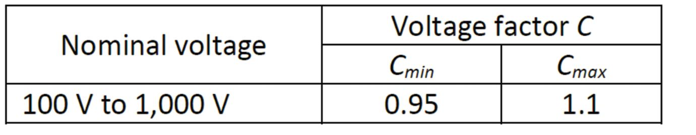
Regulations 411 4 4 and 411 5 4 incorporate a voltage factor into the equations given This voltage factor C takes account of voltage variations depending on time and place, changing of transformer taps and other considerations The voltage factor C is not intended to take into account any fault impedance
The values of C for a low voltage installation are given in Table 1, and are reproduced from Table 7 of
PD CLC/TR 50480: 20111 Determination of cross-sectional area of conductors and selection of protective devices.
The voltage factor used is dependent upon what is being considered For example, when estimating maximum fault currents, Cmax is applied When determining maximum disconnection times, Cmin is used.
The prospective fault current at position B will be:
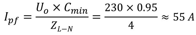
From Fig 3A1 of BS 7671, the disconnection time for the protective device is approximately 25 seconds What will be the maximum time the cable can withstand this level of fault current?
Using Table 43 1, the value of k for 70° thermoplastic insulated copper conductors is 115
The calculations show that the cable will certainly suffer some degradation as the disconnection time exceeds the time limit at which the cable can withstand the fault current
The prospective fault current at position A:
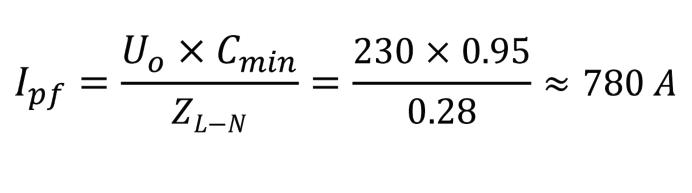
From Fig 3A1, the disconnection of the protective device occurs in a time less than 0.1 seconds, therefore the cable
will not be exposed to damage, and the fault current is within the rated breaking capacity of the device.
The two values of prospective fault current calculated highlight the condition that the most onerous situation arises when the short-circuit current is relatively low, such as at position B
Summary
This article has considered fault current and in particular focused on the effects of a short-circuit fault occurring between two live conductors
In the example given, the adiabatic equation was used to illustrate the effects and possible damage that may occur to a cable during a short-circuit fault
As such, for any relevant disconnection time, and to prevent thermal damage to the cable insulation during a fault, the maximum energy withstand of the cable must be equal to or greater than the let-through energy of the protective device
“The application of the regulations of Chapter 43 shall take into account both the minimum and maximum fault current conditions; so that the highest energy let-through is considered (533.3).”
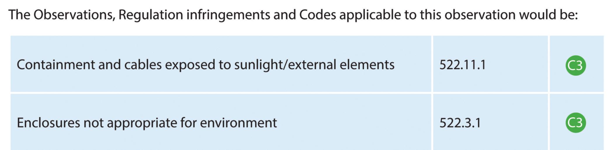
A periodic inspection and testing of an electrical installation is subject to limitations, within Section D of an EICR, where concealed cables in the fabric and containment have not been inspec ted
With this type of installation, it may not be obvious or may not be considered to investigate the external parts of the property to inspect any accessories or wiring systems This setup would appear to be for a ‘smar t ’ television installation where power, HDM i and data cables are needed at the rear of the T V, so the client would not appreciate internal room concealment or sur face containment.
The solution installed has several issues:
● M ini trunk ing is not designed for ex terior installation with no IP, Ultraviolet protec tion
● The sur face pattress boxes with blank plate gain are not designed for this use
● There is a lack of mechanical protec tion especially with access to bins, and evidence of damage to the pattress boxes
● Potential clash with band I and II cables.
There’s also an additional cabling installation, in the top right of the image, for an upstairs room with lack of protection for the cables
There’s a risk of ingress of moisture into the internal elec trical accessories due to the incorrec t installation methods, and this would include cables passing through the cavity void which may include some form of insulation material which can affect the cable rating or the insulation Care must be taken when the periodic inspection is carried out, as in the summer the evidence of water ingress may not be present
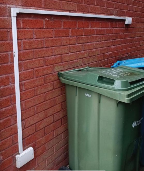
Therefore, the classification code would be a C3, Improvement recommended unless there was evidence of moisture within the internal accessories or back boxes In the latter case it would attrac t a C2, Potentially dangerous urgent remedial action required
Updated for BS 7671:2018+A2:2022, NAPIT ’s EICR Codebreakers publication is purpose -written to aid contractors, inspectors and clients, and now includes updates to align with Amendment 2 of the IE T 18th Edition Wiring Regulations The book is the per fect technical aid for electrical professionals and their customers.


Need help with cracking those all-impor tant EICR codes? Ever y month the technical team at NAPIT will be studying your latest ‘Caught on Camera’ photos and offering advice on the next steps, should you find a similar installation. If you want the team at NAPIT to help crack your codes then send your pic tures through to us at: pe@hamer ville.co.uk
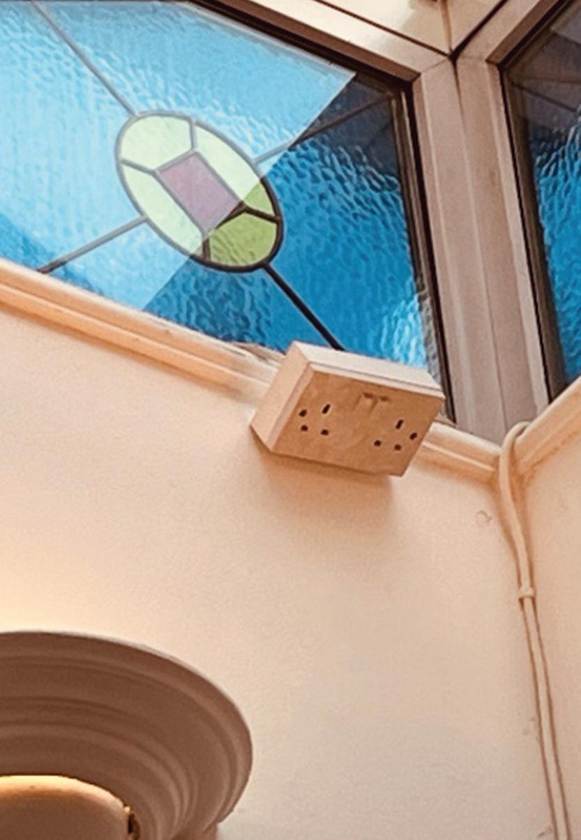
WILLIAM M CULLE TON:
T H
BS 7671 covers installations within the UK and some other jur isdic tions, unfor tunately D ublin does not fall under the requirements, therefore would not be subjec t to an Elec tr ical I nstallation Condition R epor t
The requirements in I reland fall under National Rules for Elec tr ical I nstallations E T101, where the ter m for the repor t remains as a Per iodic I nspec tion R epor t and has four obser vation numbers:
1. R equires urgent attention
2. R equires improvements
3. R equires some attention.
4. D oes not comply with the cur rent National Rules for Elec tr ical I nstallations
Although this installation would not be covered by an EICR, we will consider it as if it was
A socket- outlet has been installed at a high level, without any means of secur ing to the building struc ture This may not attrac t attention, although depending on what it has been installed for, it can present a danger to those using it
I t could be used for festive or celebration per iods for decorative lighting, which would involve staff plugging into an unsecured socket- outlet. This could place strain on the cables, ter minations and any equipment plugged into the socket- outlet
Therefore, the classification code would be a C 3, Im p rove me n t re com me n de d unless there was evidence of damage or loose connec tions to the socket- outlet or back box. I n that case it would attrac t a C2 , Po te ntia ll y d an g e ro u s urg en t re med ia l a c t io n req u i re d

The A2:2022 18th Edition Codebreakers publication is priced at £22.00 (members) and £24.00 (non-members). It is available in both hard copy and digital versions * Price is VAT exempt and excludes postage and packaging.


The Building Safety Act 2022 has introduced significant changes and responsibilities for the construction and maintenance industries. Clare Klug, Product Marketing Manager at Trimble Luckins, looks at how to manage product information for safer buildings.
The construction industry has long-since focused on health and safety practices on-site but the Building Safety Act 2022 shifts the mandate by stretching the responsibility to serve all those occupants of the building throughout its lifespan
A key focus of the Act is now the management of product information, which is deemed critical for ensuring safety and compliance throughout the lifecycle of a building The Act underscores the importance of accurate documentation, traceability, and accountability across the supply chain – from manufacturers to building owners As such, effective product information management is now essential for meeting these new regulatory standards.
With additional scrutiny on safety and information, one of the fundamental requirements of the Act is the need for precise documentation and thorough record-keeping The safety and compliance of a building depends on reliable and up-to-date information about the products used during construction and maintenance.
This is where the role of manufacturers becomes pivotal They’re responsible for providing accurate, regularly updated product data and making it easily accessible to contractors, sub-contractors, engineers, and building owners. To meet these demands, many in the industry turn to established datapools
that offer comprehensive, verified product information
These platforms remove the burden from contractors by maintaining a central database of product information, which is automatically updated via API As an example from the MEP industry, a unique TSI code assigned to each product ensures quick and easy reference to the relevant data
By using this identifier, contractors can seamlessly integrate product information into their internal systems and project documentation, ensuring compliance with the Building Safety Act
The Act introduces the concept of a “Golden Thread” of information, which
refers to a continuous digital record of all data related to a building’s design, construction, and ongoing maintenance
This is especially important for high-rise buildings, where safety is a top priority
The Golden Thread ensures that every product installed in the construction process is recorded, and that the information is kept up-to-date and easily accessible throughout the building’s lifecycle
The Act goes one step further and suggests that documentation be kept for a minimum of 15 years This certainly requires changes in working practices, with many UK contractors using industry established datapools to reference as part of their digital evidence This enables them to leverage resources from data experts that specialise in liaising with manufacturers and wholesalers to ensure the information is accurate.
Traceability is essential for ensuring that the products specified for a building are the same ones installed on-site Often, what is specified by the contractor can be replaced with other products due to availability or convenience However, this can pose risks to the building’s safety and compliance
Under the Act, maintaining the thread of information from specification through installation and into maintenance is crucial. Accurate product information allows for quick response times and safe replacements when components need to be changed during a building’s lifespan
Whether it’s 10 or 20 years later, having a complete record ensures that like-for-like replacements are made, preserving the safety and integrity of the structure. A verified product database ensures that all manufacturers, contractors, and building owners have access to the most current and accurate data at any time
Upon the completion of a construction project, it is now standard practice for contractors to provide a digital twin or as-built model of the building These digital representations contain detailed information about the building’s systems, including the materials and products installed.

This approach m building owners an teams to access th need for future rep integrating produc these models, stak reference the exac materials used. If an issue arise system years later, be consulted to ide involved and retrie or safety documen streamlined process saves time and ensures that any future work on the buildin high standards as g construction
Safety is at the core of the Act, and managing product information effectively is key to ensuring it Installation guides, maintenance manuals, and safety certifications must be readily accessible to everyone involved in the building’s lifecycle Housing this information in a central, verified database makes it easy for contractors, engineers, and building owners to retrieve the necessary documentation when needed Having accurate, accessible information instils confidence that the products being used meet regulatory standards and are safe for long-term use This not only helps ensure compliance with the Act but also provides peace of mind that the materials specified and installed will perform as intended without unforeseen safety issues arising down the line.
The Building Safety Act imposes new duties on every participant in the supply chain, from manufacturers and suppliers to building owners. Each party must collaborate to ensure the safety and compliance of the products used:
● Manufacturers must supply fully attributed product information and prove compliance with regulations They are responsible for ensuring that the information is provided in a format
that can be integrated into various systems used across the supply chain.
● Wholesalers are required to ensure that the products specified by contractors are supplied without substitutions based on stock availability or pricing preferences
● Contractors are now held accountable for assembling accurate documentation throughout the building’s lifecycle, ensuring that all records are robust and accessible
● Building owners must have access to this information for ongoing maintenance and regulatory compliance, ensuring that the building remains safe for occupants
The Building Safety Act 2022 sets new standards for product information management, with a strong emphasis on accuracy, traceability, accessibility, and safety By leveraging a robust database which provides stakeholders with what they need to uphold their responsibilities, the industry can meet these regulatory demands, ensuring safer buildings and better outcomes for everyone involved

In this article, Andrew Duffen, Technical Commercial Engineer at NAPIT, seeks to unravel the mysteries of unidirectional and bidirectional protective devices.
With the introduction of Amendment 3 of BS 7671, the requirement for the installation of bidirectional protective devices for all sources of supply, including grid connections, generating sets, i e battery storage, solar PV and electric vehicles, with the ability to power back to the charger (vehicle-to-grid), has been addressed
Amendment 3 is a standalone document and has to be included with the current version of BS 7671:2018+A2:2022 and Corrigendum (May 2023). It is a free-to download PDF and should be appended to your brown copy of BS 7671:2018
A key principle of this amendment is the safety and compliance of electrical installations as more users become prosumers in this modern world, the growth in the renewable energy market in the UK and the rising cost of energy
There are two definitions for BS 7671 in Amendment 3, describing both types of protective devices

What is a unidirectional protective device?
For a unidirectional protective device, BS 7671 Amendment 3 states:
“A protective device where it is intended by the manufacturer that a source of supply is only connected to one defined set of connection terminals ”
Unidirectional protective devices are labelled to show the line and load terminals and are intended to function when the source of supply connects solely in one direction, from the supply to the load It is essential to pay attention to the connection terminations as specified on the device, shown in Fig 1
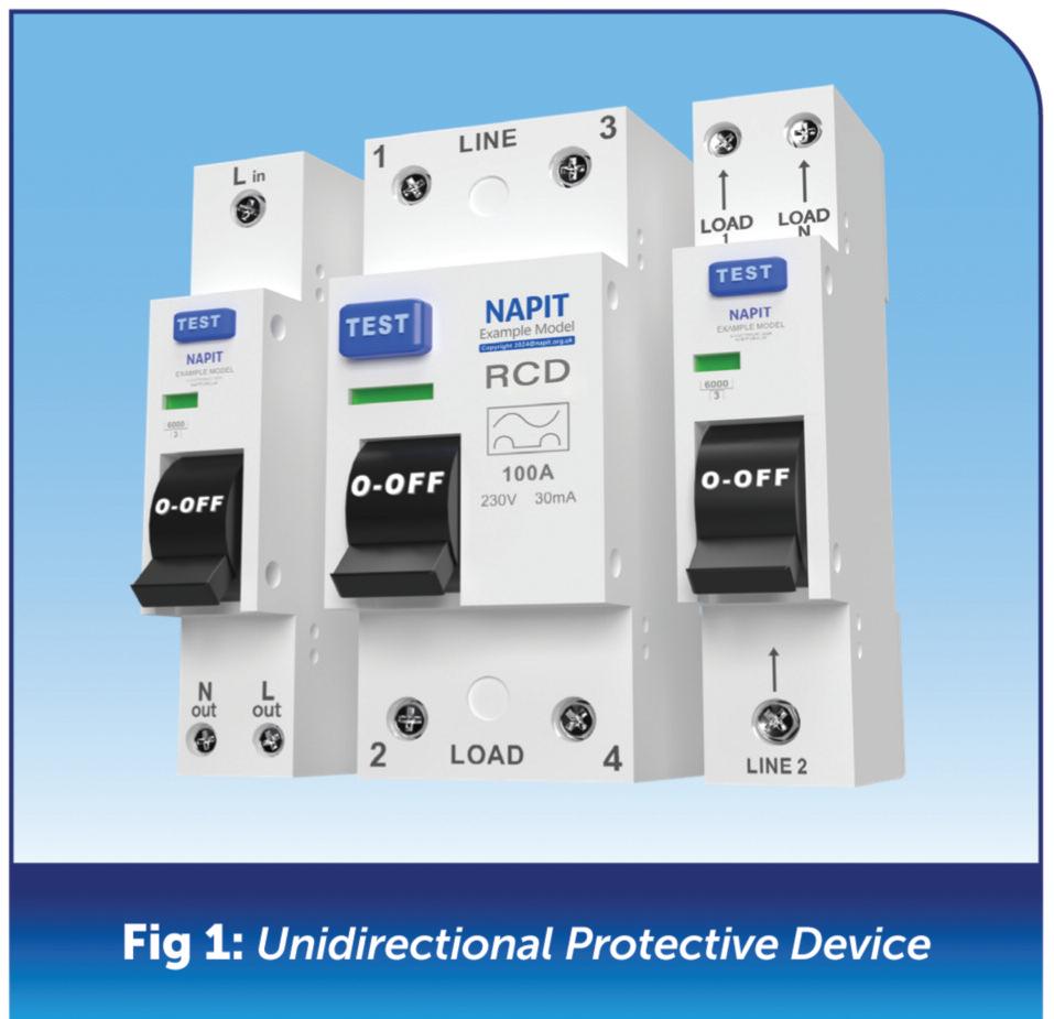
An example of this type of device is a Residual Current Breaker with Overcurrent (RCBO) Not all RCBOs are unidirectional; some RCBOs now incorporate technology that prevents the RCBO from being damaged when the source of supply is derived from either direction, making them bidirectional protective devices
What is a bidirectional protective device?
The definition of a bidirectional protective device in Amendment 3 is defined as:
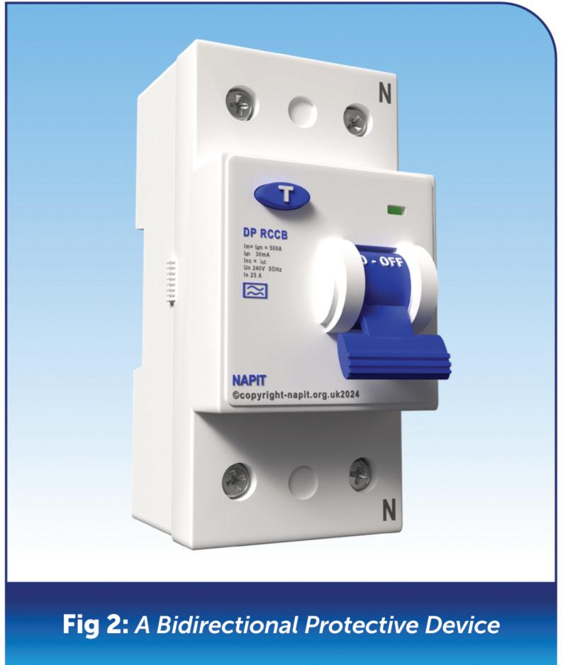
“A protective device where it is intended by the manufacturer that a source of supply is connected to either or both sets of connection terminals.”
“ ... a bidirectional protective device doesn’t have line and load terminal markings, which allows it to safely accommodate a source of supply from either direction without risk of damage.”
A n e x a m p l e o f t h i s t y p e o f d e v i c e w o u l d b e a R C C B , s e e F i g 2
G e n e r a l l y, R C C B s w i t h i n c o n s u m e r
u n i t s a r e i n t w o - m o d u l e - s i z e s , a n d d o
n o t u s u a l l y h a v e a n i n a n d o u t
i n d i c a t i o n ; t h e r e f o r e , t h e y a r e
c l a s s i f i e d a s b i d i r e c t i o n a l p r o t e c t i v e
d e v i c e s , t h o u g h t h e y c o u l d b e m a r k e d
t o d i s p l a y w h e r e t h e n e u t r a l o r l i n e
s h o u l d b e t e r m i n a t e d
RCCBs installed in split load consumer units are not suitable for the connection of solar PV or battery storage systems
How will Amendment 3 affect existing installations?
Careful consideration should be given to existing installations in regards to carrying out electrical installation condition reports (EICR) Inspectors carrying out these reports will need to give a classification code if a unidirectional protective device was installed with connections for more than one source of supply, such as a generating set
N A P I T a s p a r t o f t h e W i r i n g
Re g u l a t i o n A d v i s o r y G r o u p ( W R AG )
h a v e c r e a t e d a q u e s t i o n a n d a n s w e r
o n t h i s t o p i c w i t h i n d u s t r y c o n s e n s u s o n t h e i m p a c t o n e x i s t i n g i n s t a l l a t i o n s
To correctly assign classification codes when conducting EICRs, NAPIT and WRAG recommends checking with the manufacturer to establish if the
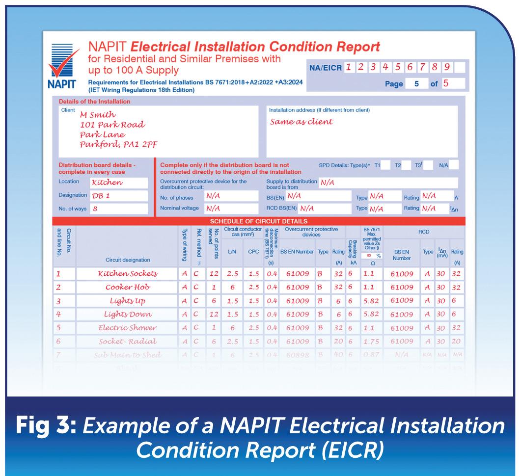
protective devices being installed are bidirectional or unidirectional protective devices and to receive a declaration of conformity which shall be appended to the EICR, as shown in Fig 3
I f a d e c l a r a t i o n o f c o n f o r m i t y i s p r o v i d e d , t h e n n o c l a s s i f i c a t i o n c o d e
s h o u l d b e r e c
After the release of Amendment 3, all sources of supply for connection to either set of terminals, including generation sets, must now be protected by a bidirectional protective device
Designers, installers and inspectors must be aware of Amendment 3, ensuring that all electrical installations that have sources of supply operating in either direction, such as generating sets, comply with the amendment Regulation 530 3 201 states:
“Selection and erection of equipment for protection shall take account of appropriate
use of either a unidirectional protective device or a bidirectional protective device ”
With rapid growth in the renewable energy industry, bidirectional protective devices will become the standard.
In regard to existing installations of generation sets, where it is unclear if the protective device is either unidirectional or bidirectional, inspectors must confirm the protective device type with the manufacturer, with either written or published confirmation of device type.
Once this information is gained, it will aid the inspector in determining any potential classification code required for an EICR
Further information on uni and bidirectional devices can be found in the On-site Solutions publication, available at NAPIT Direct.
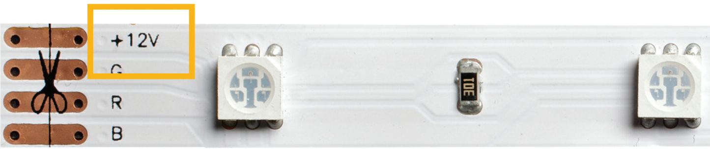
The experts at ROBUS guide you through the basics of LED strip selection and installation.


LED strip has been a game-changer in recent times
While you’re probably familiar with the exceptional energy efficiency of LEDs, the advantages of mounting LED diodes on a flexible circuit board are still emerging Simply put, LED strip is essential to the electrician’s toolkit
The first step to an LED strip installation
You cannot choose LED strip without having a clear idea of what the result should look like Can you picture it? Having this defined vision to refer to will make the next steps easier
Consider the following:
● Where will you be installing your strip?
● Is the location outdoors or indoors?
● Is there potential for water or dampness in this space?
● What kind of ambience are you aiming for? Should it be vibrant and crisp, or soft and atmospheric?
● Will the LED strip be visible or concealed?
● Is there a preference for a continuous stream of light effect?
Once you’ve identified those factors, you’re ready to start the process of selecting your LED strip!

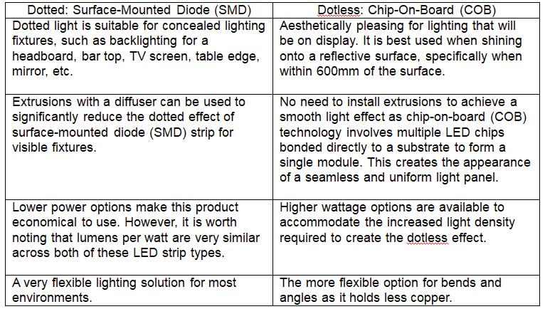
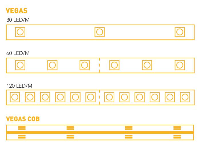
Light effect: dotted or dotless?
Why pick one lighting effect over the other? As a brand, ROBUS has a variety of dotted and dotless strip to choose from, so it’s helpful to understand the difference Take a look at the table in Fig 1 to understand the benefits of both

The key to deciding between these two options is understanding the location of the fitting and the preferred lighting effect
Once you make your choice, it is time to decide what colour lighting you require.
Colour: over 16 million options
One of the most appealing advantages of installing LED strip is the range of colour variations made possible by LED technology. RGB LEDs alone offer over 16 million possible colours, achieved by blending the primary colours of red, green, and blue – hence the name, RGB
Prefer a minimalist white aesthetic?
While RGB LEDs can approximate a white hue, you'll need a dedicated white LED chip if you want a pure white tone.

Ingress protection: how exposed is your light fixture?
Different types of LED strip come with different ingress protection ratings (IP ratings) to suit the diverse applications for which the lighting may be used. This is because electrical goods can deteriorate or malfunction when water or dust enters the fixture
Therefore, if the lighting is to be installed outdoors or in an area prone to water residue (such as a bathroom or bar), a higher-level IP rating is necessary.
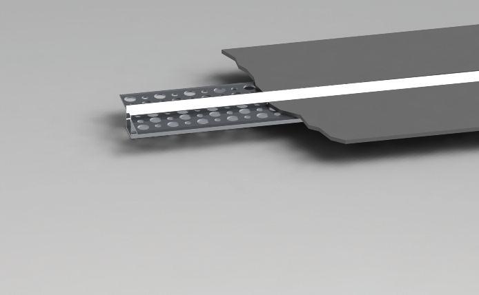
Extrusions: one to match every application
Extrusions are solid, semi-hollow, or hollow aluminium casings that can be equipped with high-quality diffusers and mounting accessories. LED extrusions, also known as profiles, prevent damage and dissipate heat Additionally, they can enhance lighting by providing streamlined effects
Exposed LED chips are vulnerable to accidental knocks and scuffs from everyday occurrences, and these lightweight extrusions act as an attractive protective shield
Wattage: what wattage and why?
It’s all down to LED density! Lower wattages are generally more suitable for accent and background lighting purposes, whereas higher output is preferred for functional lighting in areas such as offices and corridors
When it comes to LED strip, the more LEDs on a strip the more light output is produced Equally true is that the more LEDs on the strip, the more seamless the light distribution
Driver: how to choose your power supply
The type of driver you require will depend on the specific LED strip selected, the necessary length, the IP rating and the dimming capabilities required. It’s important to choose the correct driver for your installation because if it has a lower voltage than your strip, there’s a potential risk of fire
To find out what driver you need you will require the following information:
1. The LED strip voltage
2 The wattage of the LED strip
3. The length of LED strip required
4. Multiplication of the wattage by the length (W/m)
Now you know what voltage driver you need and at what wattage per metre! You can safely pair a driver that has a higher capacity than the LED strip’s power draw
Please note: you should never use a driver that has a smaller capacity than the max power of your LED strip.
Want to keep learning? You can find out about connectors, controllers, and more in The ROBUS Guide: How to Land Your LED Strip
BROWSE OR DOWNLOAD THE ROBUS ‘HOW TO LAND YOUR LED STRIP’ GUIDE BY VISITING: WWW.RDR.LINK/EBK015
CLAIM YOUR CERTIFICATE! SCAN THE QR CODE TO CLAIM YOUR CPD CREDIT FOR THIS SECTION OR VISIT: WWW.RDR.LINK/ EBK016


Click Scolmore looks at considerations to bear in mind for the selection and erection of electrical accessories in those locations that are subject to mechanical impact.


Asuitable for the location in which it is to be installed (132 5 1), and installed in accordance with the manufacturer’s instructions (134 1 1) and erected such that it is not compromised (134 1 2)
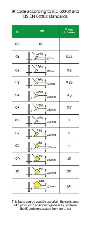
BS EN 62262: 2002+A1:2021 Degrees of protection provided by enclosures for electrical equipment against external mechanical impacts (IK code), is a standard which ‘ refers to the classification of the degrees of protection provided by enclosures against external mechanical impacts ’
Table 1 in this standard details the codes for the impact energy (in joules) that the equipment is capable of withstanding Whilst Appendix 5 of BS 7671 doesn’t reference IK codes (it references ‘low’, ‘medium’ and ‘high’ severity of impact), there are a number of regulations within the standard which make specific references to BS EN 62262, including for example, Regulation 708 512 2 1 3, 709.512.2.1.4, and 712.512.
When designing an installation, it’s important that the designer gives careful thought to the nature of the activity and conditions likely to be found in the installation
Where there is a likelihood of a risk of impact designers, amongst other things, should select products capable of withstanding such impact Whilst there are only a few regulations detailing specific parts of an installation requiring a minimum energy withstand (IK code), there is a more general need to ensure that any installed equipment is suitable.
There is a duty on installers to ensure that they install any equipment in accordance with the guidance issued by the manufacturers of a product
More than this however, they should also ensure that their activities do not compromise the product itself, which can be caused by excessive force, incorrect location, poor fixing and the like
Consider the following cases:
a) A campsite has supplies available for various tent plots Regulation 708 512 2 1 3 is very clear, and because of the increased risks associated with persons being in contact with Earth, installed equipment
must have a minimum resistance to impact of IK08 (5 J)
b) A small industrial unit has a series of wall-mounted, surface wired accessories In this instance there is no minimum declared IK value, however the general principles apply; that is to take account of the environmental conditions which apply As such, a designer would likely select metallic outlets
It is important that both designers and installers take due account of the likelihood of impact when selecting and installing suitable products for those installations which have a harsher environment Additionally, certain special locations detail specific minimum impact requirements.
Scolmore’s comprehensive Metal Clad range is offered as part of Click’s Essentials wiring accessories and features electrophoretically coated plates and back boxes that provide a durable and long-lasting heavy-duty finish. All Metal Clad socket outlets and spurs are tested and approved to BS 1363
BROWSE THE CLICK SCOLMORE METAL CLAD RANGE OF PRODUCTS AT: WWW.RDR.LINK/EBL018
Most technical support questions received by manufacturers of test and measuring instruments generally concern issues related to Earth Loop Impedance test results
More specifically, the variations in readings obtained with successive measurements,
comparisons between different test instruments, or readings that are an issue, such as just outside of the permitted minimum value for a particular installation
Why is loop testing important?
For a protective device in an electrical installation to operate within the maximum permitted time detailed on
Julian Grant,
General Manager of Chauvin Arnoux UK,
recounts how loop tests have evolved over the last 40 years and explains the inherent measurement variability that has occurred along the way.
Table 41 1 of BS 7671, the earth fault loop impedance (Zs) for the circuit must not exceed the maximum earth fault loop impedance values for the protective device given in Tables 41.2 to 41.4.
The earth fault loop path typically consists of the external impedance (Ze) and the resistance of the phase and protective conductors (R1 + R2) If the total

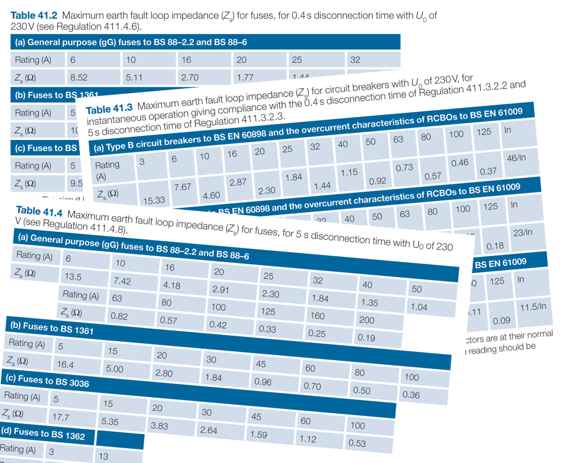
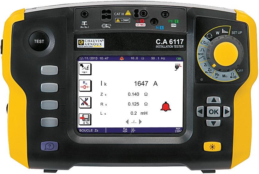
This is an issue which has been made worse over the years as loop testers have had to deal with testing on RCD or RCBO protected circuits without tripping them, and on installations with more electrical noise and harmonic currents than ever before
Back in the day
35 years ago, a loop tester would basically perform a high current test by applying a 10 Ω load to the supply being tested and then measure the voltage drop across it
It could then calculate the resistance of the loop and display it These tests were generally performed for two half-cycles of the mains supply, and with a test current of around 23 A, loop testers were able to produce fairly accurate results
Since then, installation equipment and products have evolved, and loop testers today are very different instruments
Instead of high test-currents, the introduction of RCDs and a desire to keep products small, lightweight and able to perform large numbers of tests without going into thermal overload, pushed manufacturers to utilise test currents below 15 mA and/or test durations that
are so fast the RCD does not have time to react
Even the high current loop tests in most products today only operate at a few amps, rather than the 23 A used in the past, due to the need to reduce circuit size, costs and heat dissipation This was something that became even more necessary with the need to fit the loop testing circuit into a multifunction tester as the popularity of MFTs increased
Using smaller test currents makes it much more difficult to obtain reliable measurements and increases the susceptibility of those measurements to the effects of electrical noise and harmonics, all of which reduces the accuracy of the results
This required manufactures to develop ever more sophisticated measurement techniques, resulting in different test methodologies from different manufacturers, leading to slightly different measurement results
The level of potential variability in a loop test is published in the specifications of the test instrument’s user guide, however, such things often go unread and unfortunately for many there is a natural inclination to take what is on the display as the definitive test result
Specifications and their effects
Some typical loop test specifications and the variability of result they can give on a 0 35 Ω loop are shown in the table (below) The products are not identified, but they
are all popular brand MFTs currently available in the UK and these figures are taken directly from the manufacturer’s published specifications
Apart from the accuracy % of reading, the number of digits represents variability of the least significant digit on the display
Accordingly, ±5 digits on a 0 01 Ω resolution range means the reading can be out by an additional ±0 05 Ω And a loop with an impedance of 0.35 Ω, measured on a product with 0.01 Ω resolution and an accuracy of ±5% ±5 digits, could be displayed anywhere between 0 28 Ω and 0 42 Ω which equates to ±20%
Similarly, a 0 10 Ω loop impedance measured on the same product could be displayed as 0 05 Ω or 0 15 Ω, an error of ±50%
Avoid all doubt
To avoid any doubt, always try to use an instrument where the expected loop test values for the installation under test are well within the range and limits of the instrument
Some MFTs available today, including the Chauvin Arnoux CA6117, incorporate a 0 001 Ω resolution loop test range which would be a benefit If your product measurement accuracy is inadequate for the job in hand, other methods of assessing the circuit’s characteristics might be more appropriate, such as using a calculated or enquired value for Ze
Awareness of the precise measurement capability of your equipment, and the need to understand if the variability in readings mean the loop test range is suitable or not for the job in hand, are essential to ensure accurate results If you don’t know already, look in the specifications section of the user guide or contact the manufacturer

BS 7671 requires the protection of cables during selection, installation, inspection and testing This is to ensure that the cables are not damaged
The method shown for the entr y of the meter tails into the metal enclosure has not taken into the account the requirements of Regulation 522.8.5. This ensures that cables and conductors are suppor ted and not exposed to undue mechanical strain
Regulation 526 7 is also applicable here; where a connection is made to an enclosure there will be adequate mechanical protection and protection against other external influences.
There has been no attempt to provide any form of protection by not utilising a proprietar y cable gland to secure the terminations There also has been no effor t made to protect the cables from abrasion from the sharp metal edges of crudely cut holes in the metal distribution board
The remaining metal swar f within the distribution board can result in fur ther damage to the cables and terminations.
Therefore, the classification code would be a C2, Potentially dangerous, urgent remedial action required due to the risk of damage and strain on the terminations.
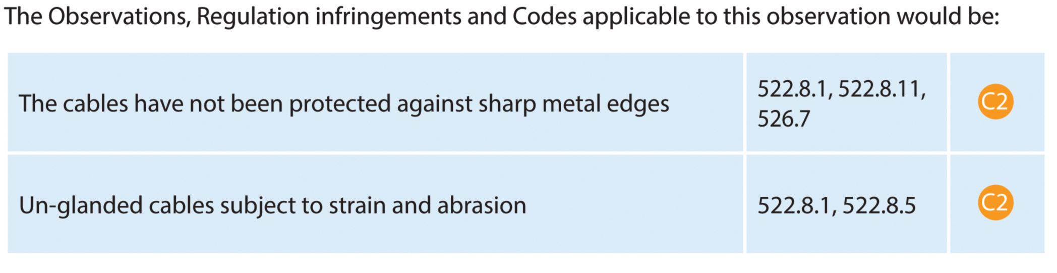
GET THE BOOK AND CRACK THOSE CODES! Updated for BS 7671:2018+A2:2022, NAPIT ’s EICR Codebreakers publication is purpose -written to aid contractors, inspectors and clients, and now includes updates to align with Amendment 2 of the IE T 18th Edition Wiring Regulations The book is the per fect technical aid for electrical professionals and their customers.
Need help with cracking those all-impor tant EICR codes? Ever y month the technical team at NAPIT will be studying your latest ‘Caught on Camera’ photos and offering advice on the next steps, should you find a similar installation. If you want the team at NAPIT to help crack your codes then send your pic tures through to us at: pe@hamer ville.co.uk
JUICE ELEC TRIC AL SERVICES: £524K WILL GE T YOU A FOUR-BED DE TACHED HOUSE IN AN EXCLUSIVE GATED DE VELOPMENT. IT WON’ T GE T YOU A
When considering the electrical design for a proper ty, whether it is a new build or a retrofit installation, the location of the wiring accessories and equipment must be considered in relation to Building Regulations along with BS 7671.
The placement of the downlight and cable within a ceiling must take into consideration the location of any structural joists and beams Under Approved Document A (Structure) it is not permissible to remove par ts of the joists, as shown in these pictures, as this would exceed the maximum notch depth.
This type of installation has been carried out without correct planning to ensure that the downlights are positioned in between the joists Clashes with joists should not be an unexpected occurrence if a sur vey of the ceiling void has been carried out.
Whenever such a clash happens the installer should re -mark the lighting layout to miss the joists, not just blindly carr y on with the installation Just because it can be made to fit does not mean it will
comply with Building Regulations and BS 7671
Apar t from the highlighted structural issues, there is an increased risk of the spread of fire with contact between the downlight and the timber sur faces
During periodic inspection and testing, this downlight installation was discovered when a sample inspection was being carried out This would now require fur ther investigation and an increased sample size as there will almost cer tainly be similar installations of downlights.
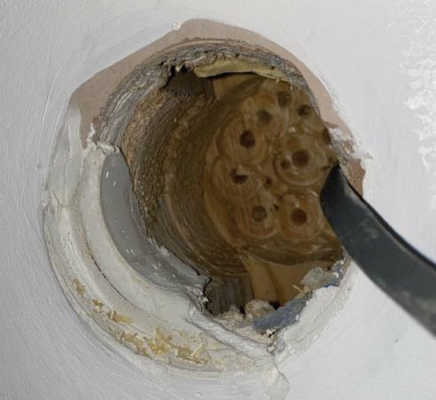
Therefore, the classification code would be a C2, Potentially dangerous, urgent remedial action required due to the risk of fire and lack of compliance with Building Regulations
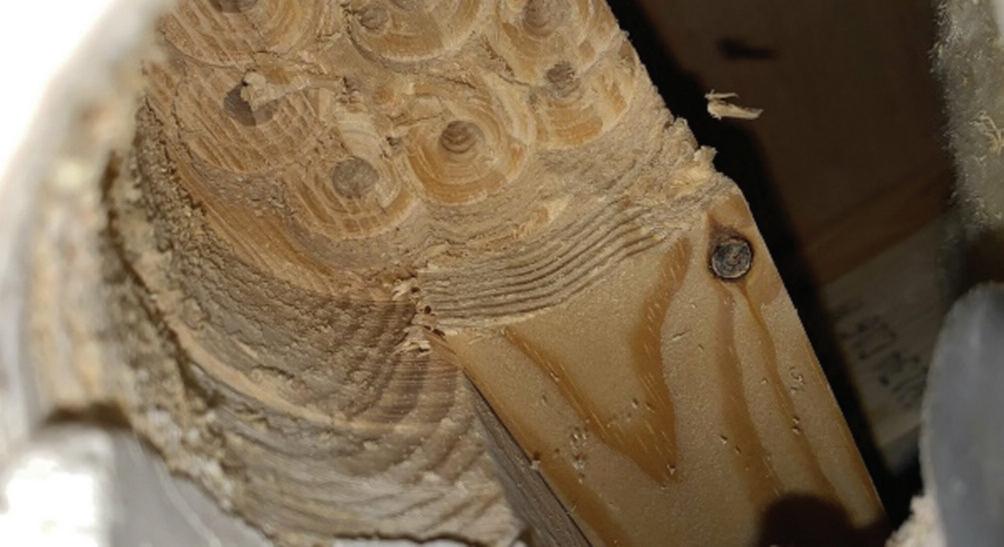
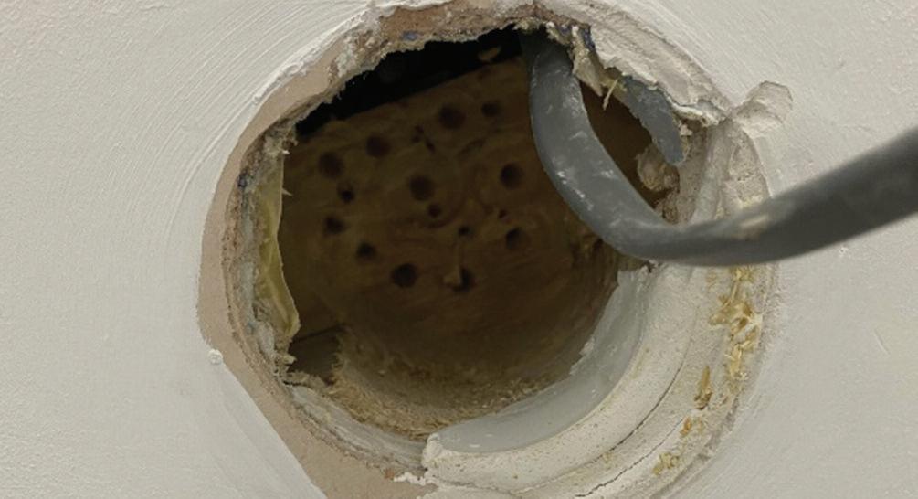
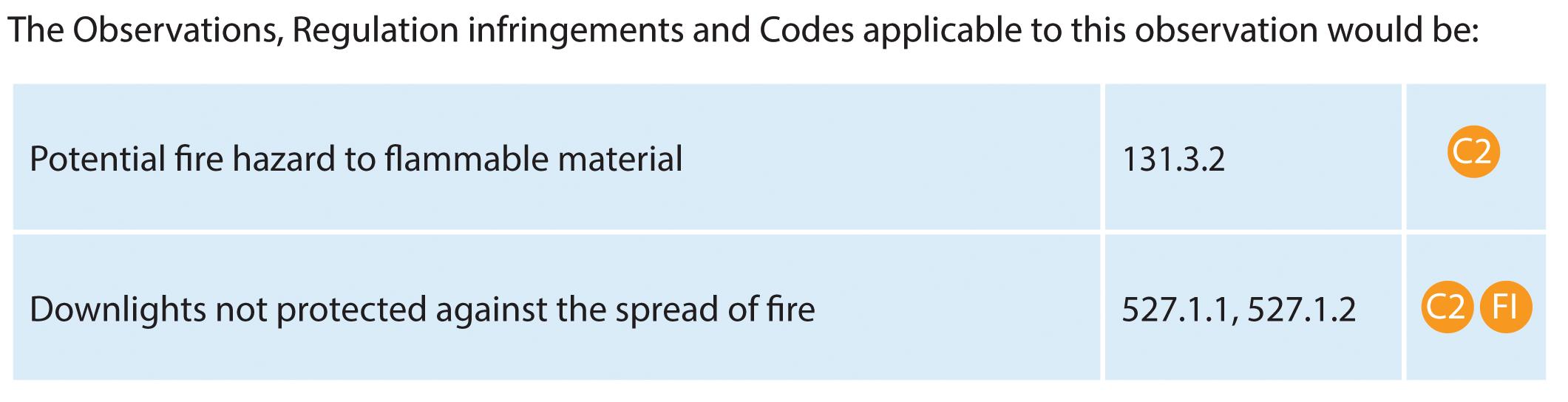
The A2:2022 18th Edition Codebreakers publication is priced at £22.00 (members) and £24.00 (non-members). It is available in both hard copy and digital versions * Price is VAT exempt and excludes postage and packaging.
I have recently signed up for the BAFE SP203 Scheme for fire alarm maintenance. What can I expect from the auditor?
Firstly, do not panic about the assessment; most auditors are not coming to try to trip you up or crucify you. Their visit is to document what you do and check you meet the BS 5839-1 standard of work and comply with the BAFE SP203-1 scheme
Hopefully, by now, you have studied the BAFE scheme document (freely available from BAFE) and are conversant with BS 5839-1:2017 (2025 version due by the end of April)
Section 6 of the standard covers maintenance, however you also need good knowledge of the rest of the standard For example, if you’re on a maintenance visit, how would you know if the system category is an L2 if you don’t have the required design knowledge?
Here’s a few pointers to help you prepare for the process:
1. Before the audit
Prepare yourself ! The auditor will let you know what items they need to see, including:
● Maintenance procedures and schedules
● Records of recent maintenance work
● Evidence of staff training and qualifications
Make sure your paperwork is complete, up-to-date, and easy to access
2. What happens during the audit?
The auditor will look at several key areas to check that you’re doing everything properly These include:
a) Maintenance processes
● Routine checks: They’ll check that you’re following the proper procedures for regular maintenance, like inspecting, testing, and cleaning fire alarm systems
● Fixing problems: They’ll want to see how you handle faults or repairs, including how quickly you respond to urgent issues
b) Recent work
The auditor will review a sample of your maintenance jobs, including:
● Maintenance reports: Do your records show what you checked, what you found, and what you fixed?
● Compliance: Are your checks in line with the rules, such as those in BS 5839-1?
● Client logbooks: Are these appropriately updated during visits?


c) Tools and equipment
They’ll check that your tools and testing equipment:
● Are suitable for the job
● Have been calibrated and are in good working order
d) Your staff
They’ll assess if your team members are qualified and trained for their roles
Expect them to ask for proof of training, qualifications, or any updates to their skills
e) Reports and communication
The auditor will ensure you give clients clear, professional reports after maintenance visits They’ll also check how you handle problems, recommend fixes, or suggest system upgrades
3. Checking your records
The auditor will look at how you keep track of your work:
● Schedules: Are you maintaining systems at the correct intervals (e g , every six months)?
● Faults/repairs: Are problems logged and fixed promptly, with clear records?

4 KEY THINGS TO FOCUS ON
1. Stick to the rules in BS 5839-1 for maintenance.
2. Keep detailed and accurate records of all work
3. Ensure your team is adequately trained and has the right tools
4 Communicate clearly with your clients, especially about problems or recommendations.
● Certificates: Are you providing proper paperwork to clients, like maintenance certificates?
4. Quality management
The auditor will check your processes for planning maintenance, dealing with complaints, and ensuring everything runs smoothly They’ll also want to see how you improve over time, like learning from mistakes or updating your procedures
5. Site visits
The auditor will want to see a maintenance visit or review how you recently handled one They’ll examine how well your team follows procedures and interacts with the client
6 Feedback after the audit
● What’s good: The auditor will tell you what you’re doing well
● What needs fixing: They’ll point out any problems, which might be:
● Minor: Small issues you need to address but don’t stop you from passing
● Major: Serious issues that need fixing quickly to keep your certification
7. Once the audit is complete
If you meet all the requirements, you’ll either get or keep your BAFE SP203-1 certification for maintenance If there are issues, you’ll need to fix them and show the auditor evidence of the changes
Top tip: If you are not happy with something the auditor says, or you think they are wrong, ask them to show you in BS 5839-1 and/or in the BAFE scheme document; no one is infallible It is very easy for someone (the auditor, you, or I) to miss something in the heat of the moment on a busy job And remember variations, if you cannot fully adhere to the standard.

DO YOU HAVE A QUESTION YOU'D LIKE ANSWERED?
EMAIL YOUR QUERIES TO: TOM@ZZEUS.ORG.UK
GET MORE DETAILS ABOUT ZZEUS TRAINING AND THE RANGE OF COURSES ON OFFER AT: WWW.RDR.LINK/EBL021
In this article, Andrew Duffen, Technical Commercial Engineer at NAPIT, presents the ultimate guide to Surge Protective Devices.
As Surge Protective Devices (SPDs) find their way into installations more often, we need to be aware of the different ways they can be installed and the different types that are available.
Not all SPDs are the same Some devices are specifically designed for use in TT installations and must be fitted in the correct part of that installation, with regards to any residual current devices (RCDs) that are installed
What is an SPD?
An SPD is a protective device that is installed to safeguard electrical systems, including the consumer unit, wiring and associated components, from power surges, which are referred to as transient overvoltages. It also provides protection for sensitive electronic devices connected to the system, such as computers, televisions, washing machines, as well as safety circuits like fire detection systems

and emergency lighting. Electronics with delicate circuitry are particularly susceptible to damage caused by these transient overvoltages
What are transient overvoltages?
Transient overvoltages are brief electrical surges that happen when energy, previously stored or introduced by other methods, is suddenly discharged These overvoltages can arise from both natural events (lightning strikes) and human activities
Man-made transients are generated by the switching of motors, transformers and certain types of lighting In the past, this was not a common issue in residential installations
However, with the rise of modern technologies such as electric vehicle chargers, air and ground-source heat pumps and speed-controlled washing machines, the likelihood of transients occurring in domestic installations has significantly increased
Natural transient overvoltages are
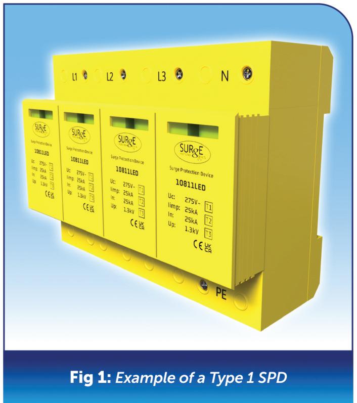
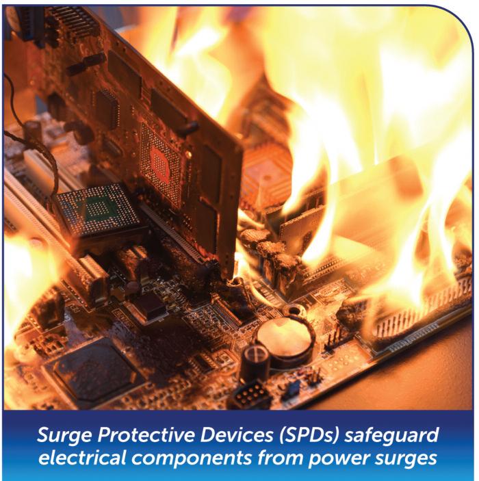
typically caused by indirect lightning strikes, often resulting from a direct strike on a nearby overhead power or telephone line As a result, the transient overvoltage can travel along the overhead lines and the distributor’s network, potentially leading to severe damage to the electrical installation and equipment connected to it
What are the different types of SPDs?
SPDs provide different functions and are classified as Type 1, Type 2 and Type 3 devices
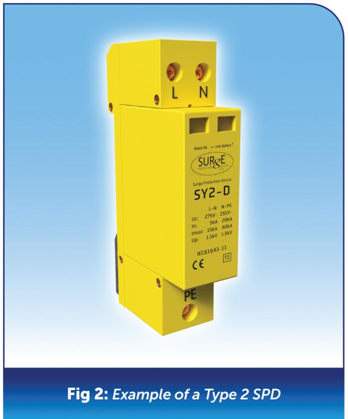
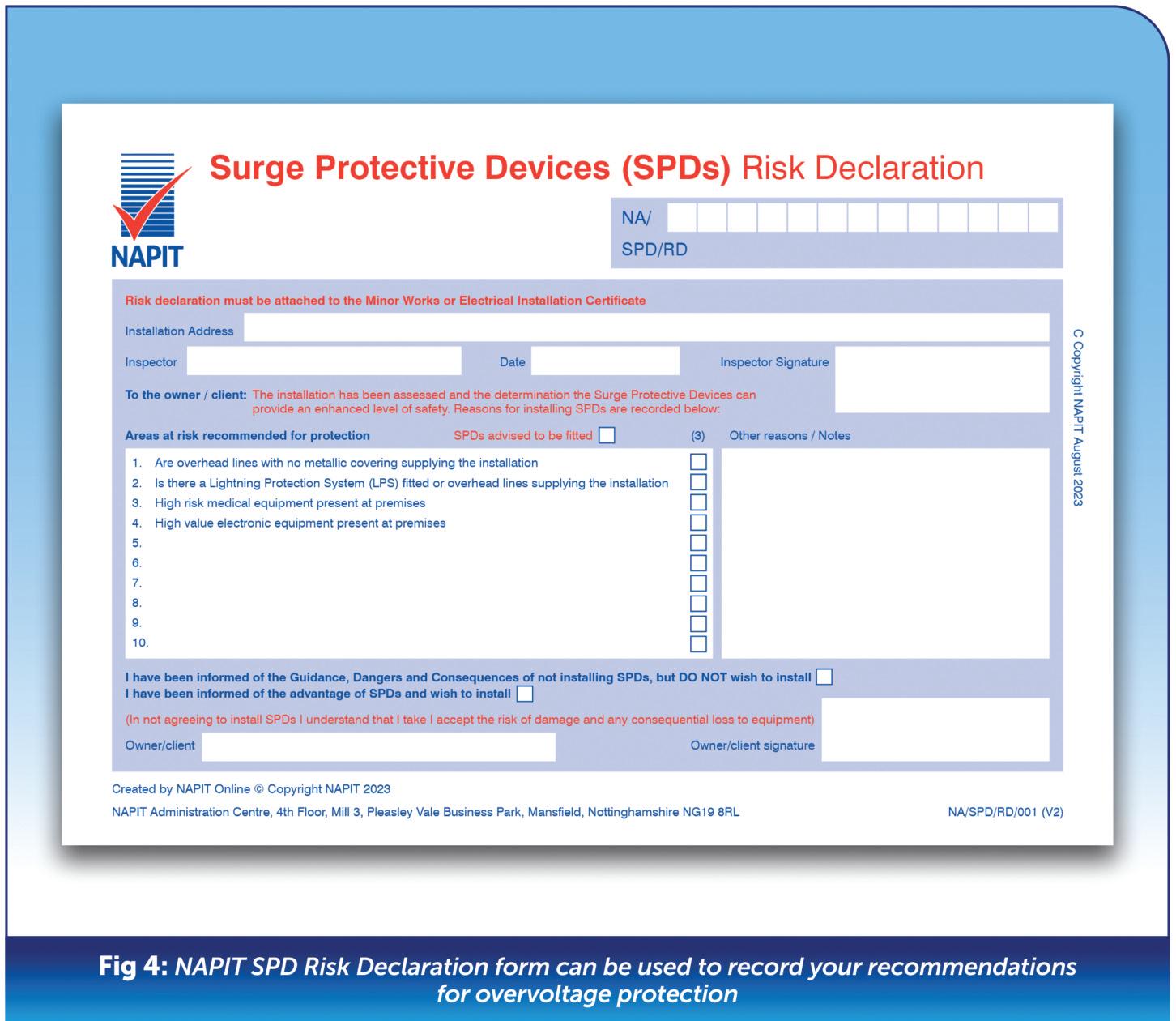
Type 1
Type 1 SPDs should be installed at the origin of the electrical installation located in or adjacent to the main distribution board These devices deal with direct lightning strikes and are also used where structures have Lightning Protection Systems (LPS)
Type 1 SPDs, as shown in Fig 1, are used at the origin of an installation and in lines to or from structures originating beyond the area of protection afforded by the fitted LPS
Also known as equipotential bonding SPDs, Type 1 SPDs prevent dangerous sparking, averting fire or shock risks It is important to note that LPS with only Type 1 SPDs fitted won’t protect sensitive equipment against failure However, Type 1/2 combined units overcome this
Type 2
Ty p e 2 S P D s m a y b e i n s t a l l e d i f t h e
s t r u c t u r e d o e s n o t h a v e a n L P S f i t t e d o r
d o e s n o t r e q u i r e p r o t e c t i o n a g a i n s t
d i r e c t l i g h t n i n g , s e e F i g 2
Ty p e 2 S P D s a r e u s e d f o r i n d i r e c t l i g h t n i n g e f f e c t s a n d a r e k n o w n a s s u r g e a r r e s t o r s W h e r e r e q u i r e d , t h e s e m a y b e
i n s t a l l e d a t t h e o r i g i n , a s w e l l a s a t a d d i t i o n a l s u b - d i s t r i b u t i o n b o a r d s T h i s
a l l o w s s e n s i t i v e e q u i p m e n t w i t h i n t h e i n s t a l l a t i o n t o b e a d e q u a t e l y p r o t e c t e d
Ty p e 2 S P D s s h a l l b e c o o r d i n a t e d w i t h a n y Ty p e 1 S P D s i n s t a l l e d a t o r i g i n .
Type 3 SPDs shall be installed close to any sensitive equipment that requires protection, such as data/server racks and cabinets, see Fig 3 Type 3 SPDs shall be coordinated with Type 1 and/or Type 2 SPDs installed at the origin
Regulation 443 4 1 requires that protection against transient overvoltages shall be provided where the consequence caused by overvoltage could result in:
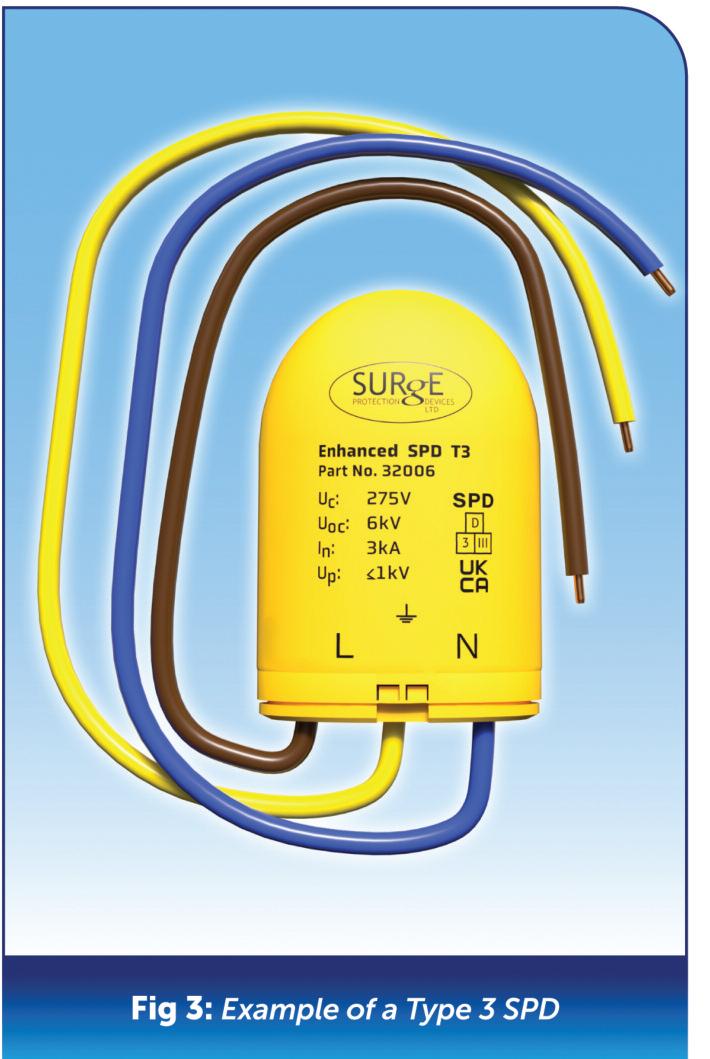
● serious injury to, or loss of human life or
● significant financial loss or data loss
For all other cases, SPDs shall be fitted to protect against transient overvoltages unless the installation owner declines such protection and wishes to accept the risk of damage to both wiring and equipment as being tolerable
Where the owner has declined SPD protection, it is important to record your recommendations for the protection against overvoltage This can be done by using the NAPIT SPD Risk Declaration form, see Fig 4
The decision to install SPDs ultimately lies with the customer, but they should be provided with clear information to make an informed choice about whether to install SPDs or not This decision should consider safety risk factors and include a cost comparison, taking into account the cost of the SPDs.
This cost should be weighed against the value of the electrical installation and the equipment connected to it, such as computers, TVs and essential devices like smoke detectors and boiler controls
“The decision to install SPDs ultimately lies with the customer, but they should be provided with clear information to make an informed choice about whether to install SPDs or not.”


To mitigate the increased risk to patients in a Group 2 medical location, the total loss of power due to a fault or a failure of supply should be prevented (710 512 1 2)
W h e r e s u c h r i s k o f l o s s o f s u p p l y i s
c o n s i d e r e d g r e a t e r t h a n t h e r i s k
a s s o c i a t e d w i t h t h e e x i s t e n c e o f a
f a u l t , t h e n a n i s o l a t i n g t r a n s f o r m e r t o
BS EN 61558-2-15 i s t o b e u s e d
p r o v i d i n g g a l v a n i c s e p a r a t i o n T h i s
t r a n s f o r m e r i n c o n j u n c t i o n w i t h t h e
m e d i c a l g r a d e i n s u l a t i o n m o n i t o r i n g
d e v i c e ( M E D - I M D ) a n d o t h e r
c o m p o n e n t s s u c h a s i n s u l a t i o n f a u l t
m o n i t o r s a n d t e m p e r a t u r e a l a r m s f o r m
t h e m e d i c a l ( I T ) s y s t e m c o n f i g u r a t i o n
I n g e n e r a l i n s t a l l a t i o n s , I T s y s t e m s
u s i n g i s o l a t i o n t r a n s f o r m e r s a r e
t y p i c a l l y r e c o g n i s e d a s o n e o f t h e
m e a n s o f p r o v i d i n g p r o t e c t i o n a g a i n s t e l e c t r i c s h o c k w i t h l i v e p a r t s i s o l a t e d
f r o m E a r t h , o r w h i l e c o n n e c t e d t o
E a r t h t h r o u g h a s u i t a b l y h i g h
i m p e d a n c e ( 4 1 1 6 1 )
H o w e v e r, d u e t o t h e i n c r e a s e d r i s k
t o p a t i e n t s , t h e m e d i c a l I T s y s t e m i s
n o t p r i m a r i l y u s e d t o p r o v i d e p r o t e c t i o n a g a i n s t e l e c t r i c s h o c k .
M e d i c a l I T s y s t e m s
T h e p r i n c i p a l p u r p o s e o f t h e m e d i c a l
I T s y s t e m i n a G r o u p 2 l o c a t i o n i s t o
i m p r o v e t h e r e s i l i e n c e o f t h e f i n a l
c i r c u i t s u p p l y i n g s o c ke
t - o u t l e t s . T h i s
e f f e c t i v e l y p r o v i d e s p r o t e c t i o n a g a i n s t
This article from the experts at NICEIC focuses on Section 710 of BS 7671 concerning electrical installations in medical locations, and aims to consider the requirements for the use of medical IT systems within a Group 2 location. Fi g 1 A t y p ic a l m e d i ca l IT s y s t e m a r r a n g e m e n t
f i r s t ( e a r t h ) f a u l t , a l l o w i n g a s i n g l e
e a r t h f a u l t t o e x i s t o n a f i n a l c i r c u i t w h i l e m a i n t a i n i n g t h e l e a k a g e c u r r e n t
w i t h i n a n a c c e p t a b l e l i m i t
D u r i n g t h i s p e r i o d t h e i n s u l a t i o n
m o n i t o r w i l l a c t i v a t e w h i l e t h e f a u l t
l o c a t i o n e q u i p m e n t ( w h e r e i n s t a l l e d )
w i l l i d e n t i f y w h i c h f i n a l c i r c u i t i s
e x p e r i e n c i n g a l o w i n s u l a t i o n f a u l t .
At t h i s p o i n t , w h i l e t h e f a u l t
r e m a i n s , w h i c h c o u l d b e o n L 1 o r L 2
( L 2 b e i n g t h e c o n d u c t o r u s u a l l y
c o n n e c t e d t o t h e ‘ N ’ o n t h e BS 1363
s o c ke t - o u t l e t ) t h e s o c ke t - o u t l e t s f r o m
t h a t m e d i c a l I T s y s t e m a r e e f f e c t i v e l y
T N s o c ke t - o u t l e t s w i t h o u t R C D
p r o t e c t i o n
I n t h e e v e n t o f a s e c o n d f a u l t t o e a r t h
o c c u r r i n g o n t h e o t h e r ‘ l e g ’ o f t h e
t r a n s f o r m e r t o e a r t h f o r a n y o t h e r
c o n n e c t e d c i r c u i t , t h e o v e r c u r r e n t
p r o t e c t i v e d e v i c e ( s ) m u s t m e e t t h e
r e q u i r e m e n t s f o r a u t o m a t i c
d i s c o n n e c t i o n o f t h e s u p p l y ( A D S )
U n l e s s t h e s e c o n d f a u l t o c c u r s o n
t h e s a m e c i r c u i t , w h e r e a s e c o n d f a u l t
o c c u r s i t i s l i ke l y t h a t t w o f i n a l c i r c u i t s
a r e a f f e c t e d T h e r e f o r e, a p p r o p r i a t e
a c t i o n m u s t b e t a ke n b y t h e u s e r s o f
t h e s y s t e m s w h e n t h e a l a r m s a r e
s o u n d e d
F i g 1 s h o w s a t y p i c a l m e d i c a l I T
s y s t e m a r r a n g e m e n t i n w h i c h t h e r e i s
n o d i r e c t c o n n e c t i o n b e t w e e n l i v e
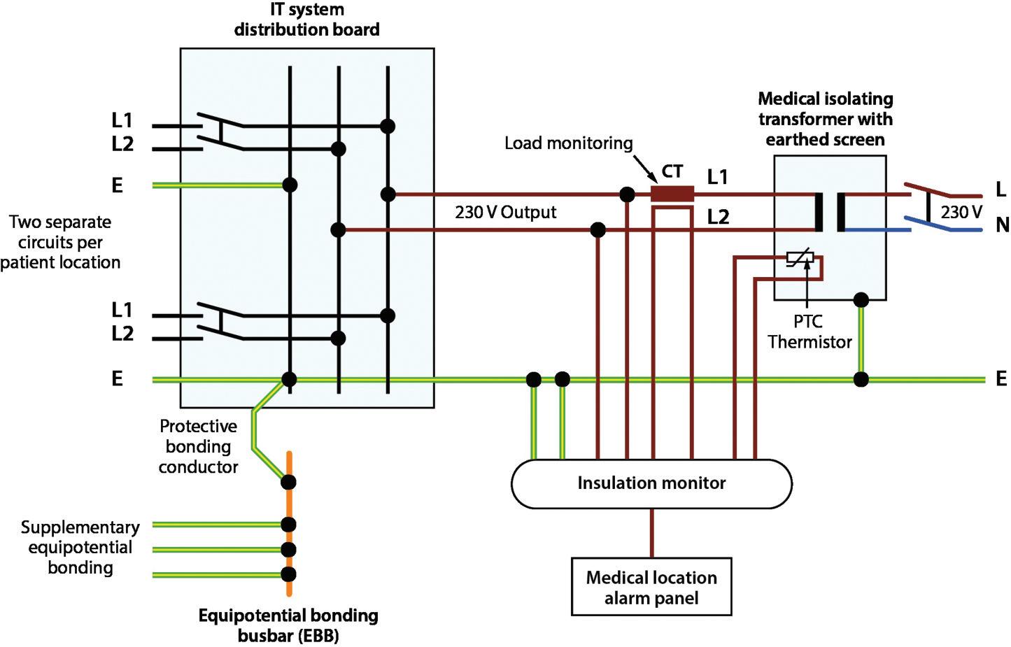
F ig 2 F l o o r s t a n d in g m e d i ca l IT s y s t e m in c o r p o r a t in g t r a n s f o r m e r s a n d d is t r ib u t io n s y s t e m
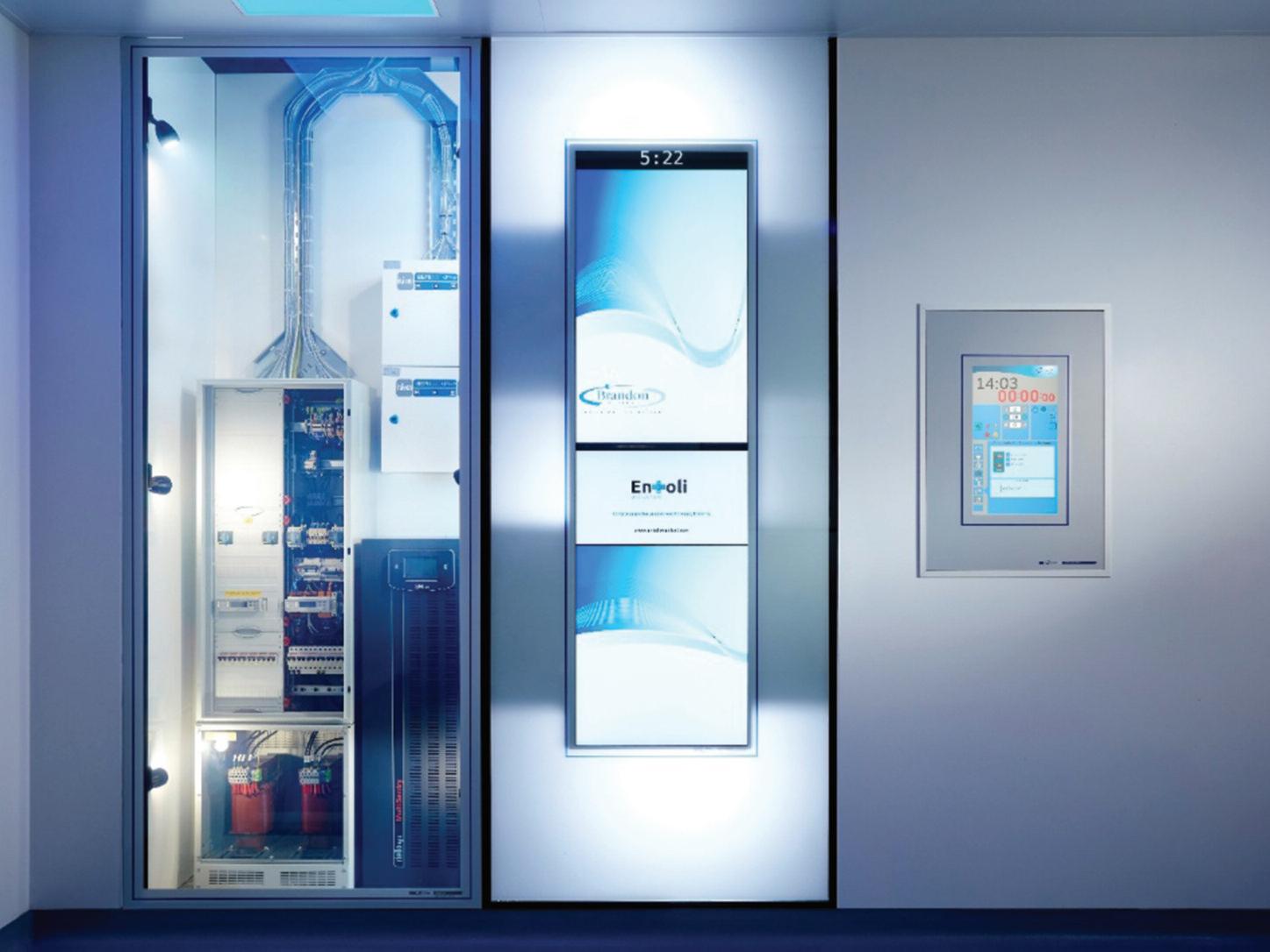
p a r t s a n d E a r t h H o w e v e r, t h e
e x p o s e d - c o n d u c t i v e - p a r t s o f t h e
i n s t a l l a t i o n a r e e a r t h e d
M e d i c a l I T s y s t e m s m a y b e h o u s e d
i n a f l o o r - s t a n d i n g c a b i n e t ( s e e F i g 2 )
i n c o r p o r a t i n g t h e d i s t r i b u t i o n b o a r d t o
BS EN 61439 s e r i e s w i t h o v e r c u r r e n t
p r o t e c t i v e d e v i c e s f o r f i n a l c i r c u i t s
w i t h i n t h e l o c a t i o n , a n c i l l a r y d e v i c e s
f o r c o m m u n i c a t i o n a n d / o r m o n i t o r i n g ,
a n d t h e i s o l a t i o n t r a n s f o r m e r i n
a c c o r d a n c e w i t h BS EN 61558-2-15
I n m a n y c a s e s , i t m a y a l s o b e
n e c e s s a r y t o i n c o r p o r a t e v e n t i l a t i o n
a n d c o o l i n g t o p r e v e n t e xc e s s i v e
t e m p e r a t u r e s a f f e c t i n g o p e r a t i o n o f
i n s t a l l e d e q u i p m e n t
Manufacturers of such systems often produce equipment having a current rating of 4 - 10 kVA (18 A - 44 A) which may incorporate single-phase 230 V 50 Hz isolation transformers, or where required, multiple transformers
W h e r e a m e d i c a l I T s y s t e m i s t o b e
u s e d i n a G r o u p 2 l o c a t i o n , i t s h o u l d
c o m p l y w i t h t h e r e q u i r e m e n t s o f
7 1 0. 4 1 1 .6 . 3 .1 , 7 1 0. 4 1 1 .6 . 3 . 2 a n d
7 1 0 5 1 2 1 1 T h e s e r e l a t e t o a l a r m s a n d
i n d i c a t o r s w i t h t h e l a t t e r r e g u l a t i o n
r e l a t i n g t o t h e p o s i t i o n o f t h e m e d i c a l
I T s y s t e m w i t h r e s p e c t t o t h e m e d i c a l
l o c a t i o n i t s e r v e s
Re g u l a t i o n 7 1 0. 4 1 1 .6 i d e n t i f i e s t h a t m e d i c a l I T s y s t e m s a r e t o b e u s e d t o
s u p p l y M E e q u i p m e n t a n d M E
s y s t e m s , a l t h o u g h i t s h o u l d b e
r e c o g n i s e d t h a t n o t a l l e q u i p m e n t i s
c o m p a t i b l e f o r u s e o n m e d i c a l I T
s y s t e m s
I t e m s o f e q u i p m e n t t h a t s h o u l d n o t
b e c o n n e c t e d t o t h e m e d i c a l I T
s y s t e m a r e i d e n t i f i e d b e l o w I t s h o u l d
b e n o t e d t h a t t h e l i s t i s n o t
e x h a u s t i v e
● S u p p l i e s t o p r o v i d e m o v e m e n t o f
f i xe d o p e r a t i n g t a b l e s .
● X- r a y e q u i p m e n t
● La r g e e q u i p m e n t w i t h a r a t e d
p o w e r g r e a t e r t h a n 5 kVA
Where a group of rooms are used to provide the same patient treatment, regulation 710.411.6.3.1 requires at least one medical IT system be provided
I n a d d i t i o n , a t l e a s t o n e
s i n g l e - p h a s e t r a n s f o r m e r s h a l l b e
p r o v i d e d f o r t h e s u p p l y o f t h e m e d i c a l
I T s y s t e m p e r r o o m , o r f o r f u n c t i o n a l
g r o u p s o f r o o m s . T h e r a t e d o u t p u t o f
e a c h t r a n s f o r m e r s h a l l n o t b e l e s s
t h a n 0 5 kVA a n d s h a l l n o t e xc e e d
1 0 kVA ( 7 1 0 5 1 2 1 1 ( i i ) )
A t y p i c a l e x a m p l e m a y i n c l u d e a
p a i r o f n e i g h b o u r i n g o p e r a t i n g
t h e a t r e s F o r r e s i l i e n c e o f s u p p l y,
e a c h t h e a t r e m a y h a v e a s e p a r a t e
m e d i c a l I T s y s t e m w h i l e s h a r i n g a n
e q u a l n u m b e r o f d i s t r i b u t e d c i r c u i t s
b e t w e e n t h e t w o l o c a t i o n s .
W h e r e t h e m e d i c a l I T s y s t e m i s
r e q u i r e d t o s u p p l y a t h r e e - p h a s e l o a d ,
a s e p a r a t e t h r e e - p h a s e t r a n s f o r m e r
s h a l l b e p r o v i d e d ( 7 1 0 5 1 2 1 1 ( i i i ) )
T h e m e d i c a l I T t r a n s f o r m e r s h o u l d
b e l o c a t e d o n t h e s a m e f l o o r l e v e l a n d
b e c o n t a i n e d w i t h i n t h e s a m e f i r e
c o m p a r t m e n t a s t h e m e d i c a l l o c a t i o n t h e y s u p p l y H o w e v e r, t h e n o t e t o
r e g u l a t i o n 7 1 0 5 1 2 1 1 i m p l i e s t h a t
w h e r e i t m a y n o t b e p r a c t i c a l o r
d i f f i c u l t t o l o c a t e t h e m e d i c a l I T
s y s t e m w i t h i n t h e s a m e f i r e
c o m p a r t m e n t , a d d i t i o n a l m e a s u r e s
m a y b e p r o v i d e d t o a c h i e v e
e q u i v a l e n t c o m p l i a n c e
S i m i l a r l y, r e g u l a t i o n 7 1 0 5 1 1 1
r e q u i r e s t h a t a n y a s s o c i a t e d
d i s t r i b u t i o n b o a r d s u p p l y i n g c i r c u i t s i n
a G r o u p 2 m e d i c a l l o c a t i o n s h a l l b e
i n s t a l l e d o n t h e s a m e f l o o r l e v e l , i m m e d i a t e l y a d j a c e n t t o o r, w h e r e
p e r m i t t e d , i n l o c a t i o n s t h a t t h e y
s u p p l y I n s u c h c a s e, c l e a r l a b e l l i n g
s h a l l b e p r o v i d e d
T h e i n t e n t i o n o f t h e s e r e g u l a t i o n s , i n a d d i t i o n t o t h a t o f e q u i p m e n t
m a n u f a c t u r e r ’s i n s t r u c t i o n s , i s f o r t h e
m e d i c a l I T d i s t r i b u t i o n s y s t e m s t o b e
i n s t a l l e d a s c l o s e a s p o s s i b l e t o t h e
c l i n i c a l p r o c e s s t h e y s e r v e, a n d , i n p a r t i c u l a r, p r o v i d e a c o n s t a n t m e a n s
o f a c c e s s i b i l i t y t o s u c h e q u i p m e n t i n
c a s e o f a s y s t e m f a u l t .
W h e n s e l e c t i n g a s u i t a b l e l o c a t i o n
f o r t h e i n s t a l l a t i o n o f t h e m e d i c a l I T
s y s t e m , p r e v e n t a t i v e m e a s u r e s m u s t
b e a p p l i e d t o m i t i g a t e t h e t h e r m a l
i m p a c t , a n d a n y e xc e s s i v e h e a t
p r o d u c e d b y t h e t r a n s f o r m e r ( s ) d u r i n g
n o r m a l u s e.
A l t h o u g h t h e w i n d i n g s o f a m e d i c a l
I T t r a n s f o r m e r a r e t y p i c a l l y d e s i g n e d
t o o p e r a t e i n e xc e s s o f 1 0 0 ° C p r i o r t o
a c t i v a t i n g a n a l a r m d u r i n g a n o v e r l o a d
c o n d i t i o n , t h e h e a t p r o d u c e d d u r i n g
n o r m a l u s e m a y i n f l u e n c e t h e
o p e r a t i n g c h a r a c t e r i s t i c s o f
o v e r c u r r e n t p r o t e c t i v e d e v i c e s , t y p i c a l l y t h o s e m o u n t e d a t h i g h l e v e l
w i t h i n t h e I T c a b i n e t
Similarly, excessive heat may create a risk of damage to neighbouring batteries used for the uninterruptable power supply (UPS) systems.
A d e q u a t e v e n t i l a t i o n o r s u i t a b l e
m e a n s o f c o o l i n g s h o u l d t h e r e f o r e b e
p r o v i d e d i n a c c o r d a n c e w i t h
m a n u f a c t u r e r ’s i n s t r u c t i o n s t o
m i n i m i s e t h e t h e r m a l i m p a c t o n s u c h
e q u i p m e n t
Le a k a g e c u r r e n t
Re g u l a t i o n 7 1 0. 4 1 1 .6 o f BS 7671 p l a c e s
a l i m i t o n t h e t o t a l l e a k a g e c u r r e n t f o r
m e d i c a l I T s y s t e m s w h i c h s h o u l d n o t
e xc e e d 1 0 m A
T h i s l i m i t t a ke s a c c o u n t o f t h e
m a x i m u m p e r m i t t e d l e a k a g e c u r r e n t
o f 0. 5 m A f o r t h e I T t r a n s f o r m e r
o u t p u t w i n d i n g t o e a r t h a n d t h e
l e a k a g e c u r r e n t o f t h e e n c l o s u r e
w h e n s u p p l i e d a t a r a t e d v o l t a g e a n d
f r e q u e n c y
T h i s m a x i m u m v a l u e a l s o i n c l u d e s
t h e t o t a l l e a k a g e c u r r e n t o f a l l f i n a l
c i r c u i t s c o n n e c t e d t o t h e m e d i c a l I T
d i s t r i b u t i o n s y s t e m u n d e r n o - l o a d , a n d
w h i l e t a k i n g a c c o u n t t h e c a b l e s
c a p a c i t a n c e ( 7 1 0 4 1 1 6 a n d 7 1 0 5 1 2 1 1
r e f e r s ) T h e p u r p o s e o f t h i s i s t o l i m i t
t h e l e n g t h o f r u n o f m e d i c a l I T s y s t e m
f i n a l c i r c u i t s b y m a k i n g t h e d e s i g n e r
c o n s i d e r t h e c a p a c i t i v e l e a k a g e
c u r r e n t o f t h e f i n a l c i r c u i t s
Installation designers should therefore refer to cable manufacturers’ data when determining the total leakage current based on the cable’s capacitance
L i ke w i s e, n o t e 5 t o r e g u l a t i o n
7 1 0 4 1 1 6 r e c o m m e n d s t h a t t h e l e n g t h o f
f i n a l c i r c u i t s c o n n e c t e d t o t h e I T
d i s t r i b u t i o n b o a r d d o e s n o t e xc e e d 2 5 m
E a c h m e d i c a l I T s y s t e m s u p p l y i n g a
g r o u p o f r o o m s w h i l e p r o v i d i n g t h e
s a m e f u n c t i o n , s h a l l b e e q u i p p e d w i t h
a n M E D - I M D, a s s h o w n i n F i g 1 ,
c o m p l y i n g w i t h b o t h A n n e x A a n d
A n n e x B o f BS EN 61557-8
S u c h a m o n i t o r i n g d e v i c e s h a l l b e
c a p a b l e o f a l e r t i n g c l i n i c a l s t a f f w i t h i n t h e m e d i c a l l o c a t i o n , o r m o r e
s p e c i f i c a l l y, w h e r e M E e q u i p m e n t i s
b e i n g u s e d , b y p r o v i d i n g a n a u d i b l e
a n d v i s u a l a l a r m w i t h t h e f i r s t f a u l t , o r g e n e r a l l y, w h e n t h e r e i s a r e d u c t i o n i n t h e i n s u l a t i o n r e s i s t a n c e t o a m i n i m u m
o f 5 0 k Ω
S i m i l a r l y, t h e I T t r a n s f o r m e r s h o u l d
a l s o b e p r o v i d e d w i t h a m e a n s f o r
m o n i t o r i n g o v e r l o a d a n d a n y i n c r e a s e
i n t e m p e r a t u r e ( 7 1 0. 4 1 1 .6 . 3 . 2 ) .
I n a d d i t i o n t o t h e i n s u l a t i o n
m o n i t o r i n g d e v i c e, e a c h m e d i c a l I T
s y s t e m s e r v i n g m o r e t h a n o n e r o o m
o r m o r e t h a n o n e p a t i e n t p l a c e o f
t r e a t m e n t , s h a l l b e p r o v i d e d w i t h a n
i n s u l a t i o n f a u l t l o c a t i o n s y s t e m
c o m p l y i n g w i t h BS EN 61557-9
( 7 1 0 4 1 1 6 3 3 )
M a n y s y s t e m s i n c o r p o r a t e a u s e r
g r a p h i c a l i n t e r f a c e, w h i c h i s o f t e n
l i n ke d w i t h o t h e r c o n t r o l s a n d b u i l d i n g
m a n a g e m e n t s y s t e m s ( B M S ) , e n a b l i n g
a c c e s s a n d c o n t r o l o f m u l t i p l e
f u n c t i o n s f r o m a s i n g l e p o i n t w i t h i n
t h e G r o u p 2 e n v i r o n m e n t s u c h a s
l i g h t i n g , v e n t i l a t i o n , a n d h u m i d i t y, a s
s h o w n i n F i g 3
T h e u s e r i n t e r f a c e e n a b l e s t h e
o p e r a t i o n a l s t a t e o f a l l I T c i r c u i t s
w i t h i n t h e m e d i c a l l o c a t i o n t o b e
c l e a r l y a n d e a s i l y r e c o g n i s e d . F o r
e x a m p l e, d u r i n g a c i r c u i t f a u l t , a n
a u d i b l e a l a r m w i l l s o u n d , a n d
c o n s e q u e n t l y t h e s c r e e n i c o n r e l a t i n g
t o t h e p a r t i c u l a r c i r c u i t w i l l c h a n g e
c o l o u r d e p e n d i n g o n i t s f a u l t
c o n d i t i o n , a s i n d i c a t e d i n i n d e n t s ( i ) t o
( i v ) o f 7 1 0. 4 1 1 .6 . 3 .1 ( s e e F i g 3 ) .
D e t a i l e d t e x t n o t i f i c a t i o n s m a y a l s o
b e d i s p l a y e d t o h e l p i d e n t i f y t h e
p r e c i s e l o c a t i o n o f t h e f a u l t T h e
i n t e r f a c e s h o u l d t h e r e f o r e b e i n s t a l l e d
i n a s u i t a b l e p o s i t i o n w h e r e M E
e q u i p m e n t i s b e i n g u s e d s o t h a t i t
m a y b e p e r m a n e n t l y m o n i t o r e d b y
c l i n i c a l s t a f f
S u p p l e m e n t a r y a l a r m s a s s o c i a t e d
w i t h t h e G r o u p 2 e n v i r o n m e n t m a y
a l s o b e r e q u i r e d a t a c l o s e b u t r e m o t e
l o c a t i o n , o f t e n p o s i t i o n e d a t t h e
n u r s i n g b a s e f o r e x a m p l e.
I t s h o u l d b e n o t e d t h a t a s n u r s i n g
t e c h n i q u e s c h a n g e, t h e l o c a t i o n o f a n
a l a r m a t t h e n u r s e’s b a s e i s n o t a l w a y s
a p p r o p r i a t e a s t h e u s e o f l o c a l
t o u c h d o w n f a c i l i t i e s e n a b l e t h e n u r s e s
t o b e w i t h p a t i e n t s T h e r e f o r e, s u c h
m e t h o d s o f w o r k i n g s h o u l d b e
c o n s i d e r e d w h e n d e t e r m i n i n g w h e r e
t h e a l a r m s h o u l d s o u n d
S u m m a r y
A l t h o u g h I T s y s t e m s a r e t y p i c a l l y
r e c o g n i s e d a s a m e a n s t o p r o v i d e
p r o t e c t i o n a g a i n s t e l e c t r i c s h o c k , t h i s
a r t i c l e i n p a r t i c u l a r h a s f o c u s e d o n t h e
r e q u i r e m e n t s o f S e c t i o n 7 1 0 a n d t h e
m e d i c a l I T s y s t e m u s e d
e a n s t o p r o v i d e a r e s i l i e n t s o u r c e o f s u p p l y i n
a G r o u p 2 m e d i c a l l o c a t i o n , o r w h e r e
M E e q u i p m e n t i s t y p i c a l l y u s e d
We would like to acknowledge and thank Brandon Medical for providing the images used within this article.

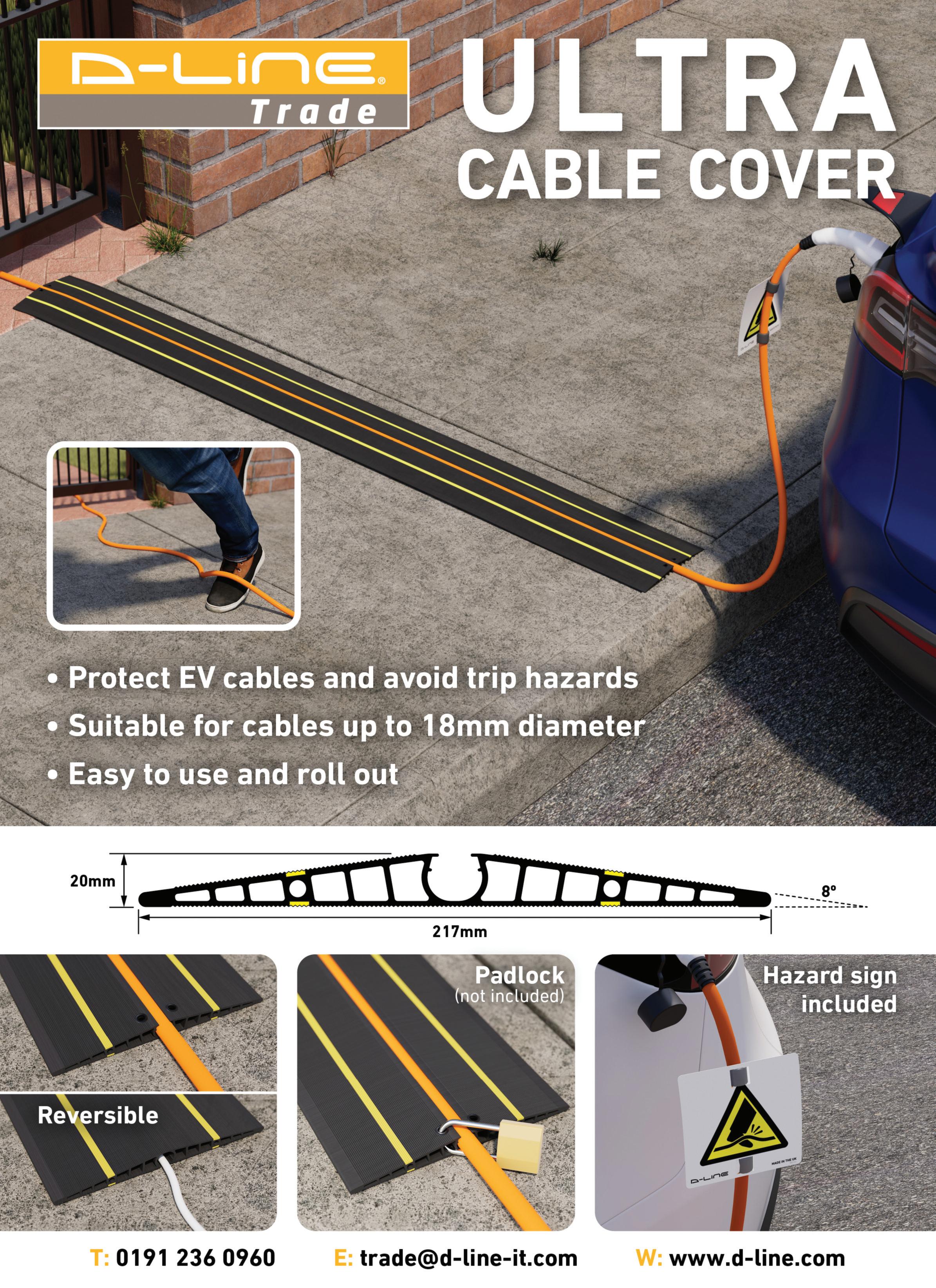
Steve Humphreys, Technical Commercial Manager at NAPIT, discusses the concept of parasitic capacitance in solar PV installations.
Parasitic capacitance might not be a term most electricians know or have even heard of It may even drum up images of bugs or other creepy crawlies in our electrical installations You might be more familiar with capacitance, perhaps from your college days, as the ability of two conductors, separated by an insulating material, to store an electric charge
The term parasitic capacitance is used to describe any ‘unintended’ or ‘stray’ capacitance in electrical and electronic equipment, conductors and components It basically arises because any two conductive objects in close proximity have the ability to store an electric charge and create a capacitance
Now we know what it is, we’ll look at parasitic capacitance in relation to solar PV systems (Fig 1) and in particular solar PV modules.
Parasitic capacitance in solar PV modules
By their design, all solar PV modules will
have an electrical capacitance in relation to their environment
This capacitance typically forms between the solar PV modules electrical conductors and surroundings, such as the frame, mounting structure, or the Earth itself

It’s worth pointing out that this capacitance has no bearing on the functionality or operation of the PV generator, hence the terms ‘unintended’ or ‘unwanted’
The presence of the capacitance is dependent on the component parts of the solar PV system in relation to the design and installation methods. This will include the physical layout of the component parts of the system, the equipment used and where the equipment has been installed
Evidence suggests there are several factors that contribute to the presence and level of parasitic capacitance in solar PV systems
During the normal operation of a solar PV system, the PV modules are connected to the grid supply via the inverter When transformerless inverters are used they can potentially allow the passage of AC voltage from the
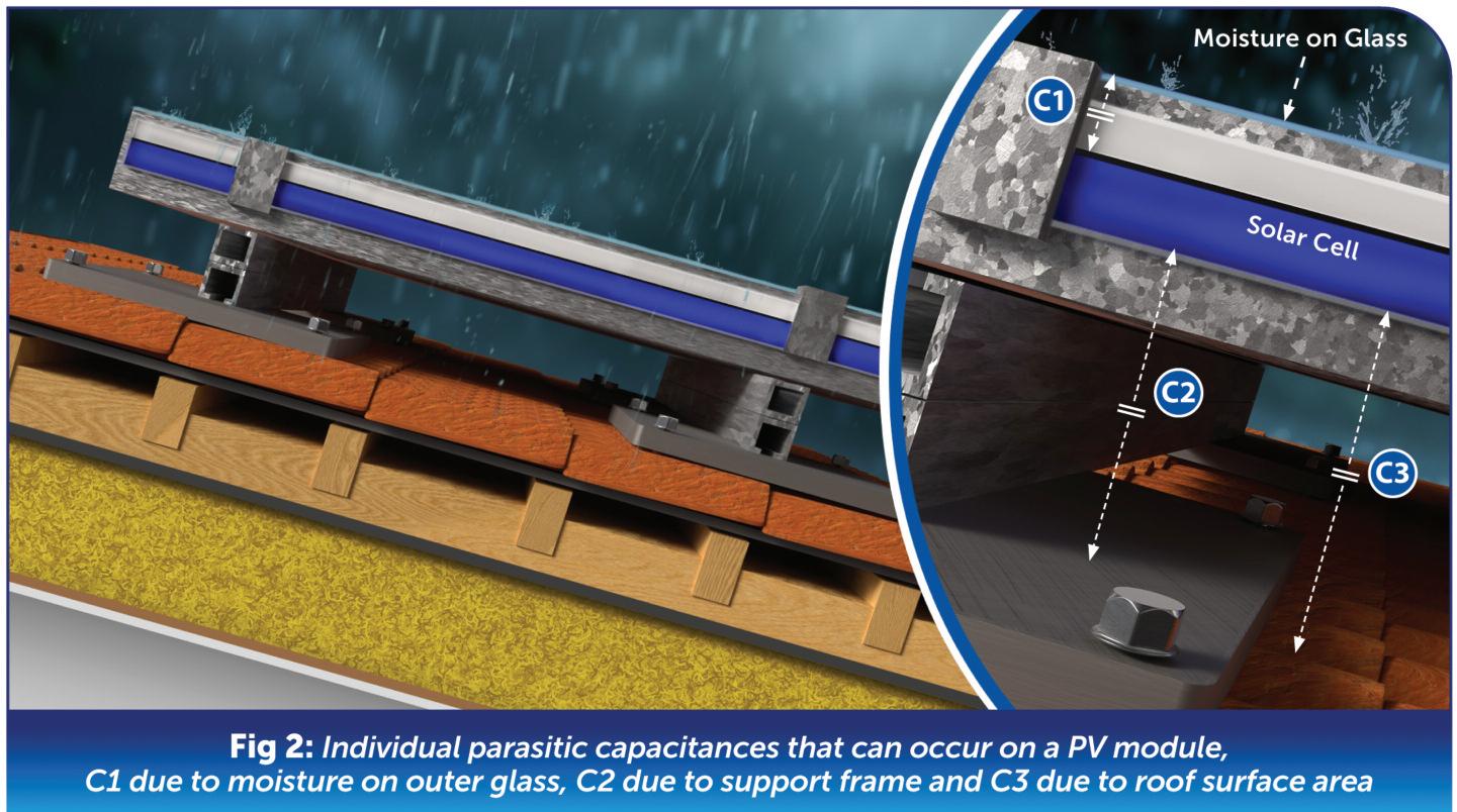
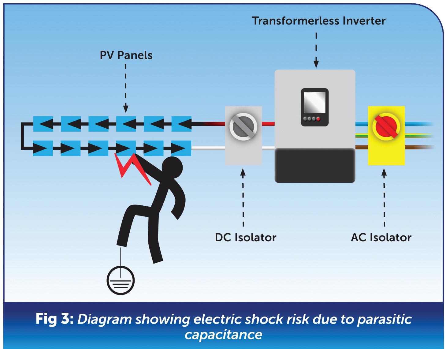
installation supply side to the DC side of the solar PV system
This alternating voltage amplitude appears at the PV module, and as a result, the PV array oscillates with an alternating voltage in relation to its environment
In single-phase transformerless inverters, up to half the AC voltage is passed on to the PV module i e 115 V/50 Hz In three-phase systems, the pass-through of AC voltage is largely supressed and therefore a much smaller voltage amplitude appears on the DC side of the system
The issue of having this fluctuating AC voltage on the DC side of the PV system is that it constantly changes the state of charge and therefore the level of parasitic capacitance on the PV array.
Weather impact
In the UK, where high humidity, dew and frequent rain are common, moisture can increase the impact of parasitic capacitance This is because the moisture can enhance conductive paths and in turn worsen leakage currents As shown in Fig 2, we have three individual capacitances – C1, C2 and C3
In wet conditions, the overall capacitance is dominated by the capacitance created by C1 due to water on the glass. Therefore, C2 and C3 do not need to be considered In dry conditions, where C1 is not applicable, the overall capacitance created by C2 and C3 is likely to be very small and therefore will not affect the solar PV system
The effect of parasitic capacitance can increase with the size of the solar
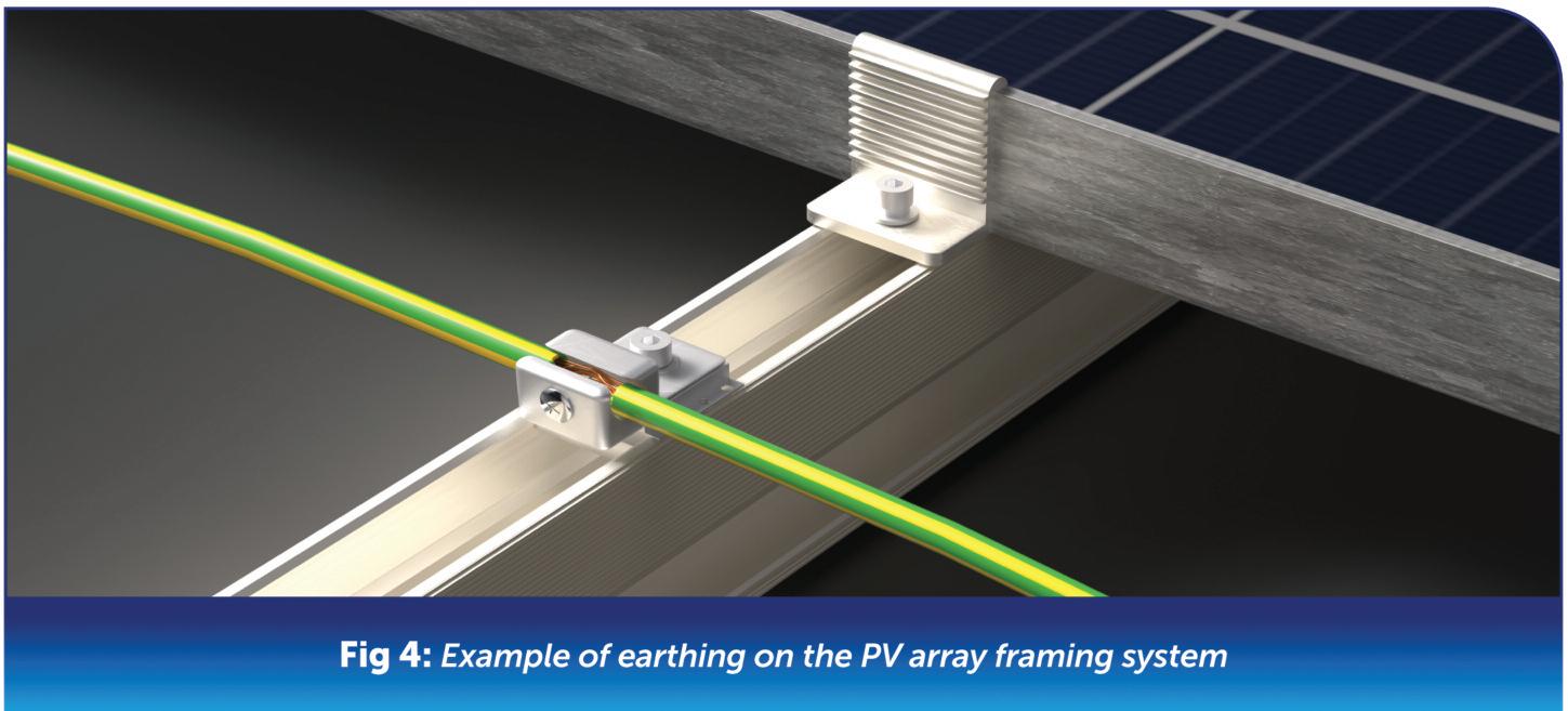
array, as larger systems have more conductive surfaces
How does parasitic capacitance affect solar PV systems?
a) Leakage currents
As mentioned earlier, when transformerless inverters are used, they can potentially allow some AC voltage from the installation supply side to the DC side of the solar PV system
This means that where there is a voltage and a resistance, there will be a current In the solar PV system, the DC side will produce parasitic capacitance leakage currents.
This leakage current has the potential to flow through a person who may be touching the PV array and in contact with any earthed metalwork Where standard modules with crystalline silicon cells are installed, the total parasitic capacitance could be around 396 nF (nanofarads) This equates to a potential leakage current of 14 mA Other types of modules, such as thin-film, could have higher leakage currents of around 20 mA
With an AC voltage of up to 115 V and leakage currents reaching potentially dangerous levels, great care is required If a person touches the array and is in contact with a path to Earth, they will receive an electric shock; it may not be sufficient to cause injury, but might be enough to cause difficulties when working at heights on scaffolding or work platforms, see Fig 3
b) Inverter efficiency
Parasitic capacitance affects the inverter’s performance, especially when it converts direct current (DC) from the solar panels to alternating current (AC).
Inverters can misinterpret leakage currents as faults or disturbances, potentially reducing efficiency and causing operational issues This could cause residual current devices (RCDs) to operate or the inverter to shut down or run suboptimally.
Parasitic capacitance can cause or worsen electromagnetic interference (EMI) in solar PV systems, which can affect nearby communication devices and systems. In highly dense areas, like cities in the UK, managing EMI is critical to ensure compliance with regulatory standards
So, what on Earth do we do about it?
To deal with the effects of parasitic capacitance, designers, installers and inspectors can take some reasonable and fundamental steps.
Firstly, compliance with BS 7671 ensures that safe electrical design practices are followed to mitigate these effects A careful and considered design would involve using high-quality inverters with better filtering capabilities and ensuring proper insulation to reduce the effects of environmental factors such as moisture.
A well thought out and robust risk assessment and method statement (RAMS) will be required to highlight the dangers of parasitic capacitance and safe working procedures This could include the use of scaffolding, other access equipment and possible insulation of metalwork
A safe system of work (SSoW) will need to be in place to ensure isolation of the inverter before any maintenance or cleaning of the array takes place Other steps that can be taken include the option to install a 30 mA RCD on the AC side of the transformerless inverter This option could cause unwanted tripping and there is also still a risk of electric shock before the RCD operates
Another option is to Earth the PV modules and array framing system, as shown in Fig 4. This option, at face value, does seem sensible and would divert the voltage to Earth However, it does create other possible issues around lightning protection, labelling for high protective conductor currents and creating a further shock risk with other extraneous and/or exposed conductive-parts
Conclusion
With the recent upsurge in renewable technology installations, such as solar PV systems, it’s more important than ever to ensure that designers and installers are fully aware of issues such as parasitic capacitance Hopefully, this article has highlighted what parasitic capacitance is, how it affects PV systems and what steps can be taken to mitigate against it.
Visit NAPIT Direct to find out more about the NAPIT Practical Guide: Solar Photovoltaic Systems publication: https://rebrand.ly/SolarPV

The column where you get to put your lighting questions to the head of the Ovia lighting business, Mike Collins, and his team of technical experts.
CCT DO YOU RECOMMEND FOR HEALTH CARE ENVIRONMENTS SPECIFICALLY?
CCT (Correlated Colour Temperature) in lighting refers to the colour appearance of a light source, measured in Kelvin (K) It describes whether the light appears war m (yellowish) or cool (bluish) The CCT Scale is as follows:
● War m White (2700K - 3000K) – a soft, yellowish light similar to incandescent bulbs
● Neutral White (3500K - 4500K) – a balanced, natural white light
● Cool White/Daylight (5000K - 6500K) – a br ight, bluish-white light, similar to daylight.
As far as healthcare environments are concer ned, it would depend on the specific areas being considered A general over view of recommendations is as follows:
● For patient rooms and recover y areas where a war m and calming lighting solution would be required a CCT of 3000K is recommended.
● For operating theatres and examination rooms where a br ighter, cooler light for high visibility is necessar y, the recommendation would be a CCT of 4000K - 6000K
● For nurses stations and corr idors a balanced light that suppor ts aler tness but is not too harsh is required, with a recommended CCT of 4000K
● For waiting areas war mer tones to offer a welcoming and soothing environment could be created with a CCT of 3500K - 4000K.
A more impor tant requirement for a surgical area would be that the CRI (Colour Rendering Index) should be 90 or higher CRI measures how well a light source shows colours and works on a scale from 0 to 100, with 100 being the best Among the luminaires from Ovia’s commercial range that offer suitable CCT solutions are the Inceptor Slate Backlit power and CCT switchable LED panels and the Sprite recessed TRIAC dimmable LED downlights with CCT switch


In this regular column, NICEIC’s team of expert technical engineers will address crucial questions they’ve received. Here are some of the most recent enquiries.
For compliance with BS 7671, can a 230 V AC fan be installed in Zone 1 of a domestic bathroom?
a) Yes b) No
The answer is a) Yes
Regulation 701 55 states that: “In Zone 1, only the following fixed and permanently connected current-using equipment shall be installed, provided it is suitable for installation in Zone 1 according to the manufacturer’s instructions:” and the list includes “(viii) Ventilation equipment”
Therefore, as the fan would fall within the definition of ventilation equipment, its installation would be compliant providing the manufacturer confirms that it is suitable for installation within Zone 1 of a bathroom and the fan has a minimum degree of protection of IPX4 against external influences.
The required external influence is specified in Regulation 701 512 2 which states that: “Installed electrical equipment shall have at least the following degrees of protection: (i) In Zone 0: IPX7 (ii) In Zones 1 and 2: IPX4”.
Which of the following should NOT be used as an earth electrode?
a) structural metalwork b) lead sheath of cables
c) water utility pipework d) earth tape
The answer is c) water utility pipe
Regulation 542 2 2 states that: “Suitable earth electrodes shall be used The following types of earth electrode are recognised for the purposes of the Regulations: (i) Earth


rods or pipes (ii) Earth tapes or wires (iii) Earth plates (iv) Underground structural metalwork embedded in foundations or other metalwork installed in the foundations (v) Welded metal reinforcement of concrete (except pre-stressed concrete) embedded in the ground (vi) Lead sheaths and other metal coverings of cables, where not precluded by Regulation 542 2 5 (vii) other suitable underground metalwork ”
And Regulation 542 6 states that: “A metallic pipe for gases or flammable liquids shall not be used as an earth electrode The metallic pipe of a water utility supply shall not be used as an earth electrode Other metallic water supply pipework shall not be used as an earth electrode unless precautions are taken against its removal and it has been considered for such a use”
What is the minimum size of a supplementary bonding conductor if mechanical protection is not provided?
a) 2.5 mm2 b) 4.0 mm2 c) 6.0 mm2 d) 10.0 mm2
The answer is b) 4.0 mm2
Regulation 544 2 1 states that: “A supplementary bonding conductor connecting two exposed-conductive-parts shall have a conductance, if sheathed or otherwise provided with mechanical protection, not less than that of the smaller protective conductor connected to the exposed-conductive-parts If mechanical protection is not provided, its cross-sectional area shall be not less than 4 mm”.

Steve Dunning, Managing Director of Martindale Electric, advises on how to ensure you are carrying out Portable Appliance Testing (PAT) correctly.
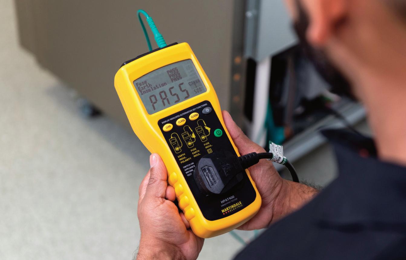
Every year, a significant number of electrical accidents, many involving portable appliances, are reported to the Health and Safety Executive (HSE) in the UK In accordance with the Electricity at Work Regulations (1989), any electrical equipment that has the potential to cause injury must be maintained in a safe condition
Designed to help raise the standards of electrical safety in the workplace, portable appliance testing ensures that electrical appliances and equipment which have been classified as “portable”, are safe to use.
For the purposes of PAT testing, portable appliances are defined as those that use a flexible cable or plug and socket This means if an appliance has a plug connected to a wall socket or generator, it should be PAT tested. This definition includes either hand-held or hand-operated equipment,
intended or likely to be moved (Refer to the Fifth Edition of the IET Code of Practice for full definition)
To help companies with their portable appliance testing strategy there are many commercially available PAT training courses These are invaluable to help provide the necessary theoretical and practical knowledge to undertake testing and inspecting different electrical appliances
While the Fifth Edition of the IET Code of Practice emphasises the need for risk assessment, partly to reduce unnecessary testing, it still requires that a competent person carry out Portable Appliance Testing.
When undertaking inspection and testing, a training course will provide a high level of knowledge needed and give invaluable information on the right test equipment to use, the ability to use it properly, and the ability to properly understand the test results.
However, even for an experienced user of portable appliance testers there are 12 potential errors which need to be carefully avoided:
1) Lack of visual inspection
It may seem obvious, but before you measure the condition of an appliance, make sure that all its parts are there –and in good condition Any signs of damage should be reported as well as any dents/scratches on the casing These can indicate that the appliance has been dropped or handled incorrectly at some point in its life. If the cable shows signs of wear or isn’t plugged in properly, this should be recorded as it could indicate that the appliance is unsafe
2) Not carrying out the tests in the required order
If on a Class 1 appliance you do the insulation test first, you don’t know if the
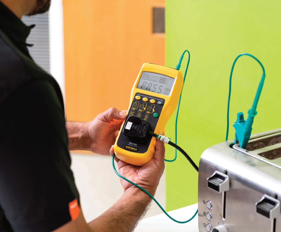
conductive earth path is good (in Class 1 appliances most PATs use the earth wire as the return signal path, which is why you don’t need to use a probe for the insulation test) If the earth path isn’t tested and proven good, you can’t rely on the insulation test
3) Forgetting to switch the appliance on
Think about the situation where the live wire is broken inside the appliance and touching the outer casing When you do the insulation test, everything inside the appliance should be at 250/500 V The tester detects (via a probe or the earth wire) any voltage escaping to the appliance housing But if you haven’t switched it on the voltage can’t get through the live wire, nothing will escape and you could have an incorrect pass of a dangerous appliance
4) Touching the appliance
The reality is that most appliances pass the insulation test, so you get into the habit of holding drills etc to make it easier to hold the probe in contact Then one day the appliance insulation fails and results in a shock
5) Only conducting one earth bond test
If an appliance has multiple, apparently
isolated, outer parts with separate earthed paths, each one needs to be separately measured (some of the earliest testers had standard test sequences that only expected you to do one earth test)
6) Taking an average reading
If you have multiple earth paths, don’t take the average reading – it’s the worst case that matters
7) Trying to undertake an earth bond test on a Class II appliance
It will, of course, fail as Class II appliances have no earth This is a very common problem and causes a large number of calls to technical helplines
8) Only carrying out one insulation test
For the same reason as #5, this is a common fault At how many places on a power tool could the insulation break down? Obviously at the chuck, but what about the ventilation slots, the trigger, the assembly screws, the speed control?
9) Not checking the fuse is conducting (see point #3)
You don’t have to carry out a separate fuse test – the function test will prove that the appliance is both on and the fuse is okay.
10) Failing to conduct a functional test (powering it up)
Some entry level PATs don’t have the ability to power up the appliance. If your PAT tester doesn’t then plug the appliance into the wall socket (after PAT testing) and make sure it works properly Putting your initials on a PASS label for an appliance that doesn’t work or is obviously faulty is a bit embarrassing
11) Not testing at the correct voltage
It’s very common for people to make the mistake of performing a 500 V test on surge protection extension leads These require a lower voltage 250 V test, which is especially helpful when testing appliances with surge protected circuits, such as sensitive IT equipment at 250 V
12) Not calculating the correct pass level
Many appliances use longer power cables than those specified by the manufacturer The current pass level for an appliance with a longer power cable is calculated differently than the pass level for an appliance with a shorter power cable The current pass level for an appliance with a longer power cable can be determined by a calculation available in the PAT code of practice
Given the importance of PAT testing and the wide variation in operating environments and equipment to be tested, it is extremely important to ensure the right equipment is selected to suit the application Often overlooked but vitally important when choosing a tester is to ensure all bases are covered not only on appliances but also with mains extension leads It’s also important to consider accessories early in the selection process such as labels and adaptors for appliances etc. Ideally, a unit will have a good range of readily available accessories for use across a wide range of applications
BRENDAN O ’CONNOR: THE CUSTOMER WANTED A SECOND OPINION ON A BOARD CHANGE. “ THE WORST DIY JOB E VER ” WAS A FAIR OPINON, DON’ T YOU THINK?
When elec tricians are called to site and come across poor standards of installation work carried out by householders this does cause a great deal of frustration (and rightly so).
There is a lack of protec tion from the sharp metal edges of the consumer unit k nockouts for the meter tails and other final circuits, Regulations 522 8 5 and 526 7 have requirements for mechanical protec tion and suppor t of cables and terminations.
The termination of the meter tails to the main switch has resulted in exposed copper where either the cable did not have sufficient length to re -terminate or just another poor method of installation
The unused entr y hole in the base of the consumer unit and the lack of insulation for the copper busbar allows access to live par ts
The use of a black conduc tor for the ear thing conduc tor shows a lack of
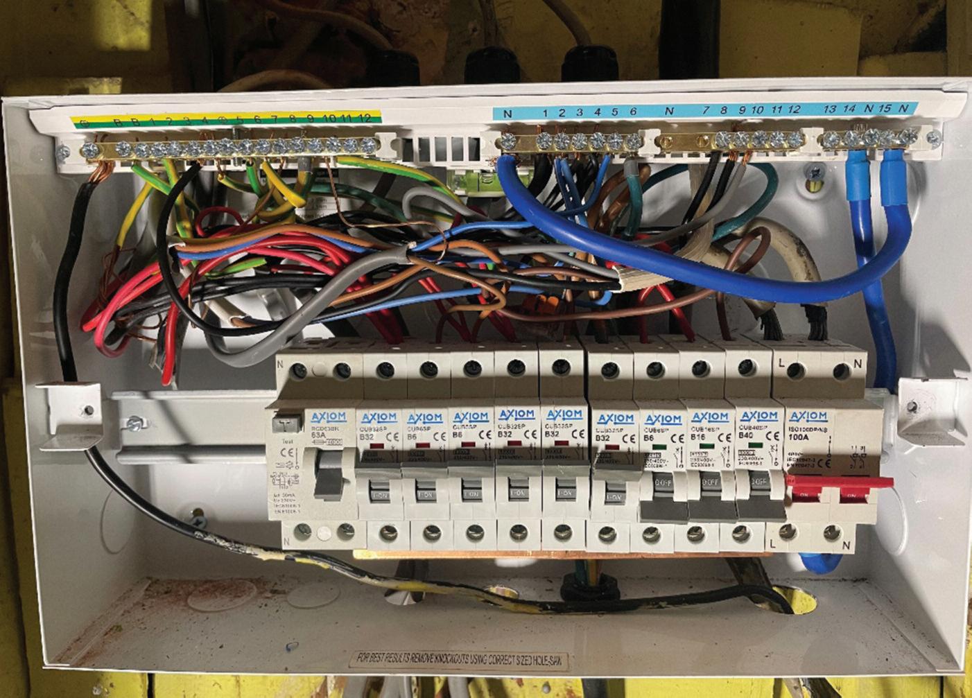
k nowledge of the requirements for BS 7671, and this also appears to be undersized.
Therefore, the classification code

would be a C1, D anger present, risk of injur y, immediate remedial ac tion required due to the risk of contac t with live par ts
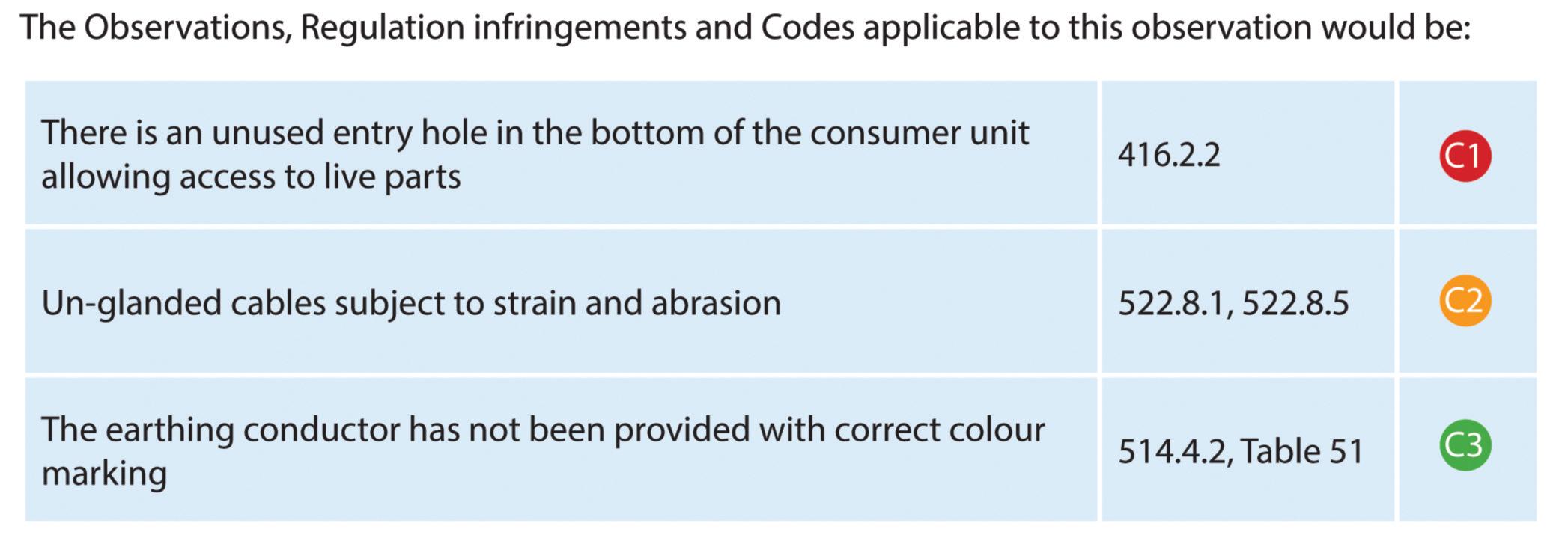
GET THE BOOK AND CRACK THOSE CODES!
Updated for BS 7671:2018+A2:2022, NAPIT ’s EICR Codebreakers publication is purpose -written to aid contractors, inspectors and clients, and now includes updates to align with Amendment 2 of the IE T 18th Edition Wiring Regulations The book is the per fect technical aid for electrical professionals and their customers.
Need help with cracking those all-impor tant EICR codes? Ever y month the technical team at NAPIT will be studying your latest ‘Caught on Camera’ photos and offering advice on the next steps, should you find a similar installation. If you want the team at NAPIT to help crack your codes then send your pic tures through to us at: pe@hamer ville.co.uk
BAILEY: THIS WAS DISCOVERED ON A RECENT INSPEC TION. JUST HIDE IT BEHIND A FRIDGE AND NO ONE WILL NOTICE…
O ften when some form of alteration has been carried out on an electrical installation, and in this case a k itchen upgrade, existing accessories are not in the correct locations for the new appliances.
There are correct methods for connection
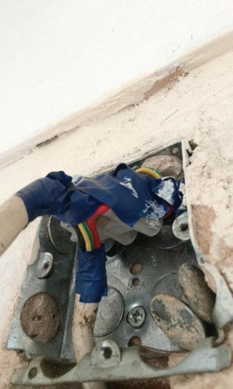
of conductors and unfor tunately covering open connectors with insulation tape and then covering with plaster is not one of them
There is a lack of suppor t or protection against abrasion for the cables, including the location of the concealed cables where they
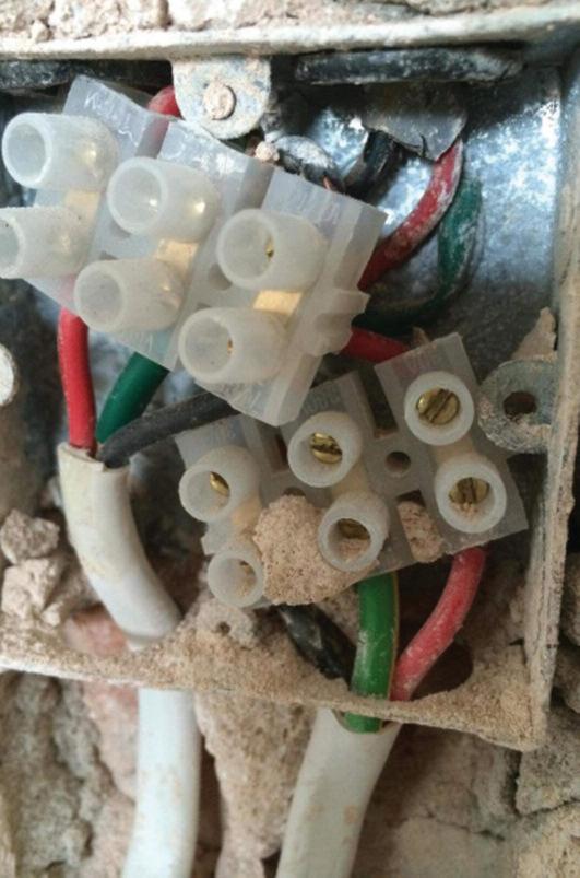
are no longer in the prescribed zones due to the removal of the accessories
Therefore, the classification code would be a C2, Potential dangerous, urgent remedial action required due to the poor terminations
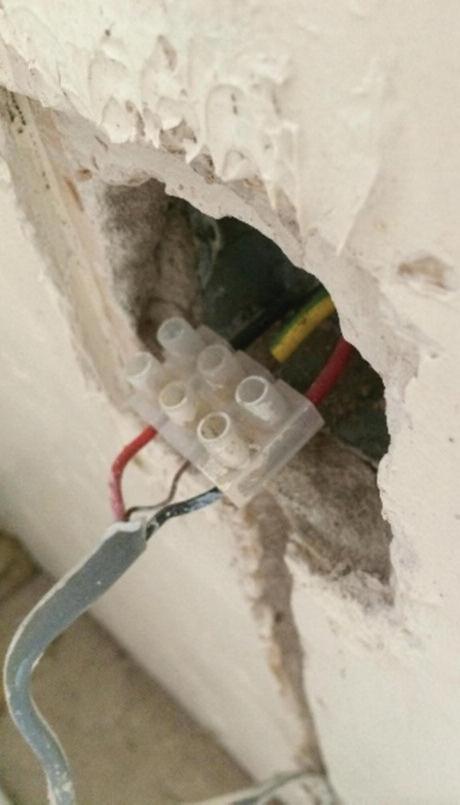
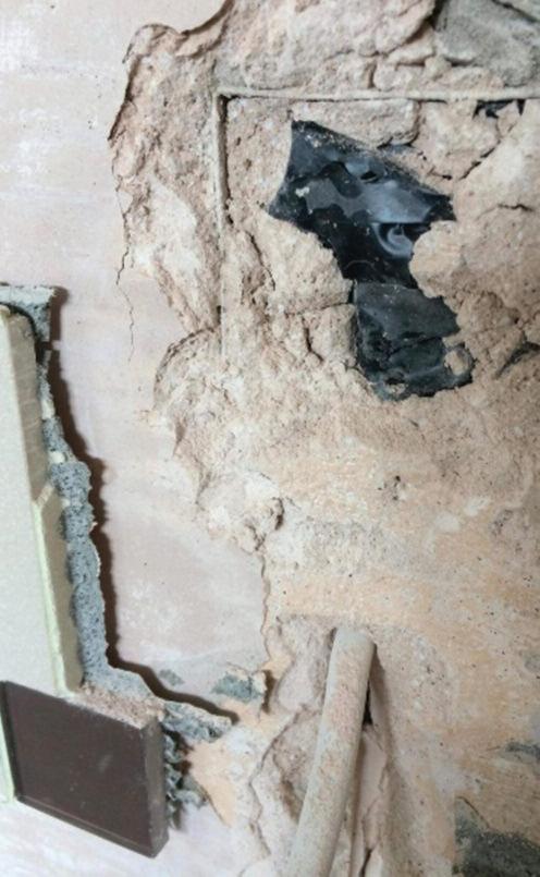
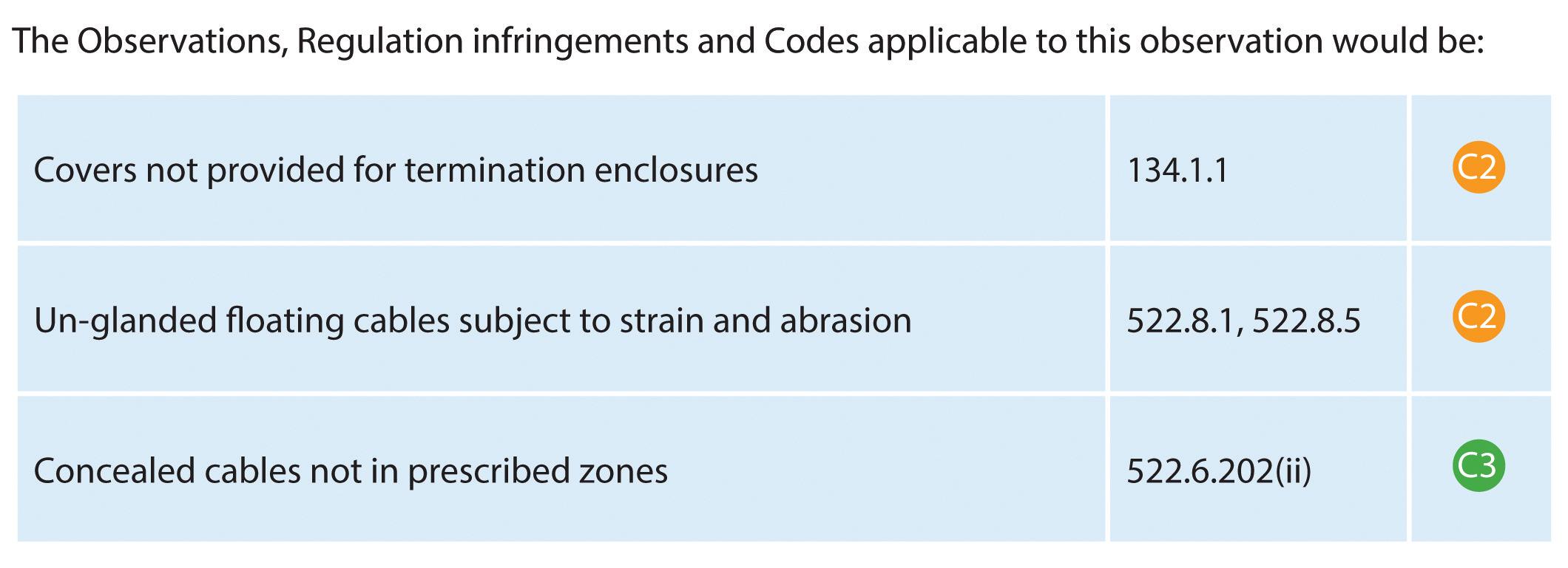
The A2:2022 18th Edition Codebreakers publication is priced at £22.00 (members) and £24.00 (non-members). It is available in both hard copy and digital versions * Price is VAT exempt and excludes postage and packaging.
ORDER YOUR COPY OF NAPIT CODEBREAKERS BY VISITING: WWW.RDR.LINK/EBM060


This article from the experts at NICEIC looks at the factors to be considered when providing protection against overvoltage in a domestic premises having a service fuse of rating not exceeding 100 A per phase.
Once it has been determined that overvoltage protection is required at a domestic premises it is essential that the system put in place is sufficiently robust to provide the required level of protection throughout the electrical installation
Factors to consider
The following factors have to be taken into account when designing and installing an overvoltage protection system:
● Does the structure have an external lightning protection system?
● What is the system earthing arrangement at the premises?
● Is there sensitive equipment within the installation that may require local protection?
● What are the distances between overvoltage protective devices and the equipment to be protected?
Does the structure have an external lightning protection system?
Where SPDs are required to protect the electrical installation in a building having an external lightning protection system (LPS) or other methods of protection
against direct lightning strike, Type 1 SPDs, also known as equipotential bonding SPDs, must be installed as close as possible to the origin of the electrical installation (534 4 1 3) These Type 1 SPDs are installed to prevent dangerous sparking which could lead to fire or electric shock hazards However, such SPDs, installed alone, do not provide protection against failure of sensitive electrical and electronic systems As a result, it is necessary to install additional SPDs of Type 2 and/or
Type 3 to protect equipment within the installation (see Note to 534.4.1.1). Typically, most modern equipotential bonding SPDs will be combination Type 1 + 2 devices
Where Type 1 SPDs are installed at, or near, the origin of the installation, each live conductor shall be connected to either the main earthing terminal or the main protective conductor – whichever route is shorter This is known as Connection Type 1 (CT 1), or common mode protection – see Fig 1
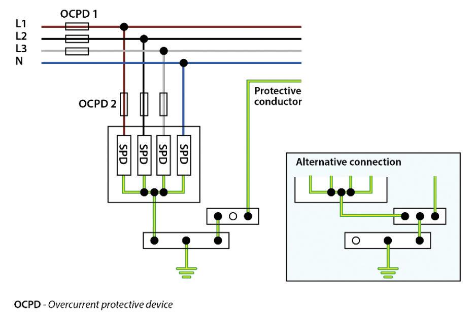
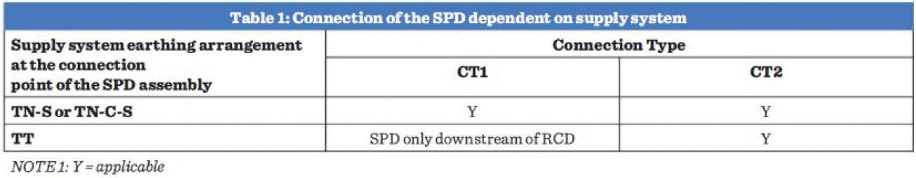
Where the Type 1 SPDs are selected using BS 7671, rather than carrying out a risk analysis in accordance with BS EN 62305-2, the impulse discharge current of the SPD (Iimp) shall not be less than the values stated in Table 534 4 (534 4 4 4 2) For Connection Type 1, the minimum permissible Iimp is 12.5 kA whether connection is between L-PE or N-PE for both 1-phase and 3-phase supply systems
Where a structure has an LPS, a coordinated SPD system connected in both power and signal lines is required (Clause 7 of BS EN 62305-41) as part of an overall surge protection management plan (Clause 9 2 of BS EN 62305-4)
As a result, where a structure has an LPS, the surge protective measures should preferably be designed in accordance with the BS EN 62305 series and not Sections 443 and 534 of BS 7671
System earthing arrangement at the premises
Where SPDs are required by Section 443 to protect the electrical installation in a building not having an external LPS, or not requiring protection against the
effects of direct lightning, Type 2 SPDs must be installed as close as possible to the origin of the electrical installation (534 4 1 4)
Where the building is not protected against direct lightning strike, the Type 2 SPDs for use at or near the origin of the installation shall be selected based on their minimum nominal discharge current (Inspd) and the Connection Type employed (534 4 4 4 1)
Where Type 2 SPDs are installed at, or near, the origin of the installation, the choice of Connection Type that is required is dependent on the system earthing arrangement
Combination Type 2+3 devices are readily available
Where the installation forms part of a TN system, in general both Connection Types CT1 and CT2 may be employed
Whereas Connection Type CT1, described earlier in this article, sees line and neutral conductors connected to protective earth (PE), with Connection Type 2 (CT2) the SPD is connected between line and neutral and between neutral and PE via either the main
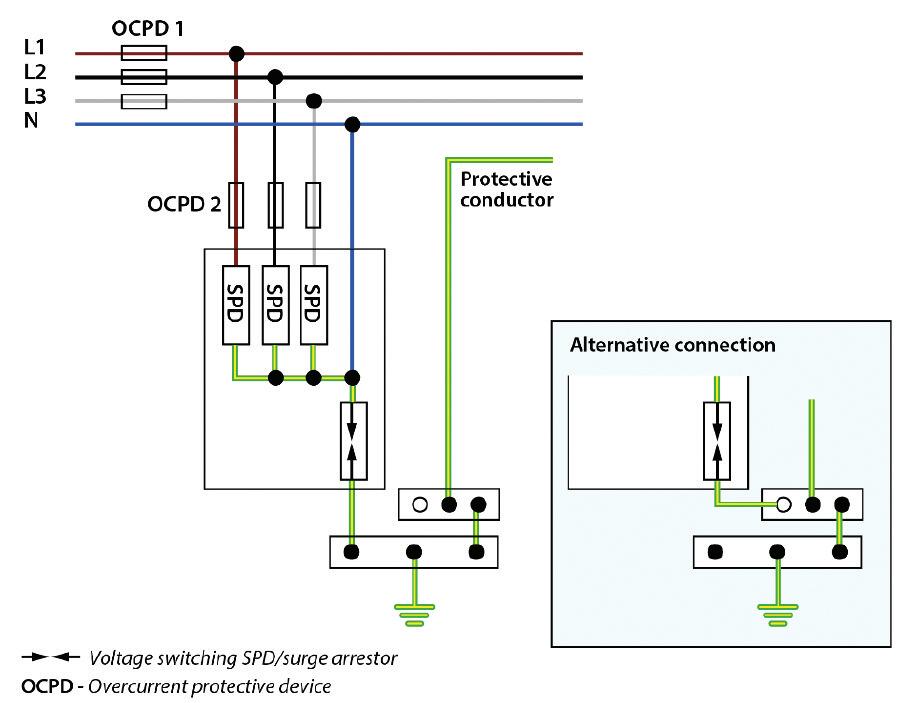
earthing terminal or the protective conductor – whichever route is shorter. Connection Type 2 (CT 2) is also referred to as differential mode protection (534 4 2 & 534 4 3) – see Fig 2
Typically, an RCD providing fault protection will be situated at or near the origin of an installation forming part of a TT system The presence of this device
affects the choice of permissible
Connection Type
● Where Connection Type 1 (CT1) is used, the SPD arrangement should be installed downstream of any RCD at or near the origin to provide fault protection – see Fig 3
● Where Connection Type 2 (CT2) is used, the SPD arrangement should be installed upstream of any RCD at or near the origin to provide fault protection – see Fig 4
● It should be noted that it is not recommended to install Type 1 SPDs downstream of an RCD (534 4 7)
Table 1 (pictured above) is based partially on Table 534.5 of BS 7671 and summarises the possible modes of protection that may be required for various LV systems in domestic premises
Is there sensitive equipment within the installation that may require local protection?
In a typical domestic premises, containing more commonplace, readily available and, relatively speaking, moderate value electrical equipment the overvoltage protection installed at the origin will generally be sufficient regardless of circuit length
However, where high-value items such as high-end home cinema equipment or hard to replace items of equipment are present, additional overvoltage protection from Type 2 + 3 SPDs should be installed close to the equipment to be protected.
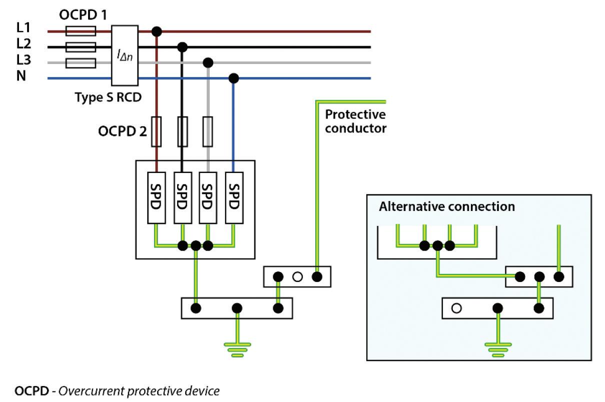
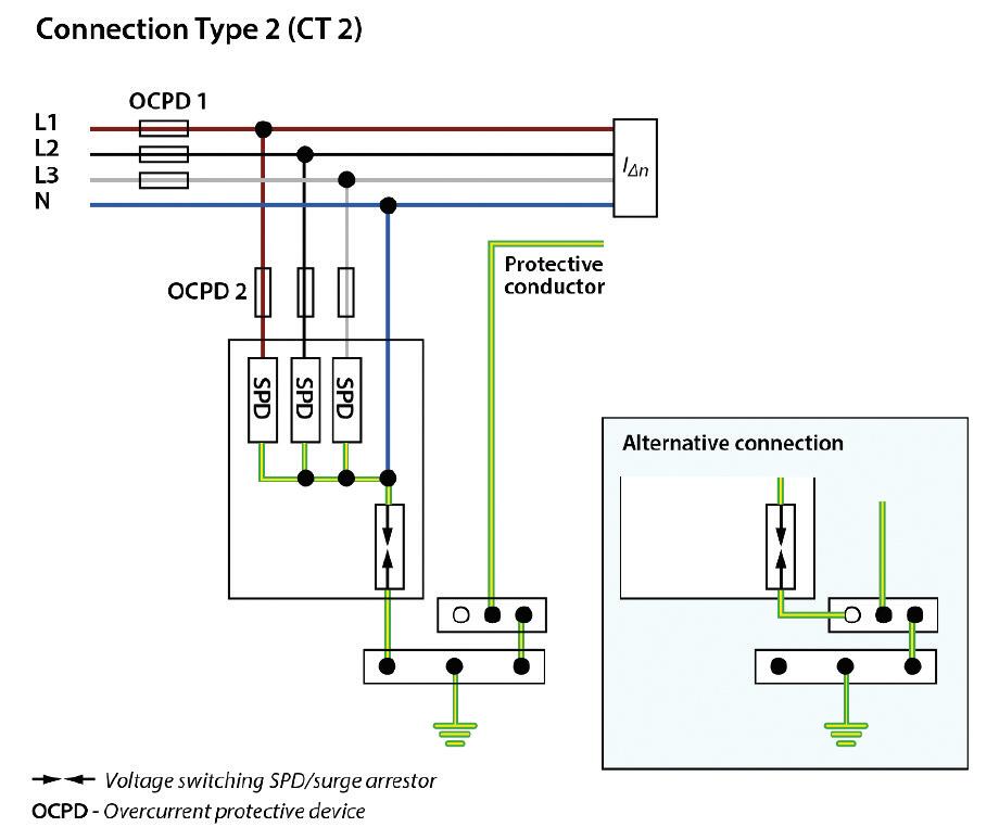
These may be situated in fixed socket-outlets or in mobile socket-outlet trailing leads conforming to relevant product standards, see Fig 5 (534 4 1 1) or within consumer units serving the equipment to be protected (534 4 1 5)
What are the distances between overvoltage protective devices and the equipment to be protected?
If the distance between an SPD and the equipment to be protected exceeds 10 m, it may be necessary to install additional SPDs between those at or near the origin and those close to sensitive equipment (534 4 4 2)
Additional SPDs may also be required if the protection level (Up) of the SPD at/near the origin of the installation is higher than the impulse immunity of the equipment.
In general, neither of the aforementioned factors is applicable in most domestic premises, as there are typically no inductive loads within the structure which could be a source for switching transients downstream of the SPD installed at the origin of the installation.
What about home offices or workshops external to the dwelling?
Many people now work from home either fully or in a hybrid capacity in small offices or workshops Where these are situated in the main body of the domestic premises, as mentioned previously in this article, the overvoltage protection provided at the origin of the installation is likely to offer sufficient protection against overvoltage
However, if the home office or workshop is in a building separate to, but supplied from, the dwelling overvoltage protection may be required as a result of the distance between the SPD at the origin of the dwelling exceeding 10 m and where the damage caused by an overvoltage could result in significant financial or data loss (443 4 1) This overvoltage protection may be incorporated in a small locally installed consumer unit (534 4 1 5)
Summary
In general, for a ‘typical’ domestic dwelling, a single surge protective device (SPD) installed in or close to the consumer unit serving the property will be sufficient. However, in some cases, such as where connected equipment of significant value is present or where a supply extends to buildings separate to the dwelling, it may be necessary to install further suitably coordinated SPDs of the correct type situated close to the items to be protected
We would like to acknowledge the kind assistance of Samad Khan of ABB Furse in the production of this article
The team at Envirovent advises on the considerations professionals need to make when sourcing appropriate ventilation equipment for the application/environment in question.
Th e r e h a v e b e e n s i g n i f i c a n t
r e c e n t c h a n g e s t o b u i l d i n g
m e t h o d s , r e g u l a t i o n s a n d
b e s t p r a c t i c e c o m p l i a n c e, i n
p a r t i c u l a r r e l a t i n g t o
v e n t i l a t i o n w i t h t h e u p l i f t s t o
A p p r o v e d D o c u m e n t F i n E n g l a n d
a n d Wa l e s b a c k i n 2 0 2 2 a n d t h e
D o m e s t i c Te c h n i c a l H a n d b o o k f o r
S c o t l a n d i n 2 0 2 3
T h e s e u p l i f t s w e r e p a r t o f t h e
F u t u r e H o m e s a n d B u i l d i n g St a n d a r d ,
w i t h f u r t h e r u p d a t e s e x p e c t e d i n
2 0 2 5 , e n s u r i n g t h a t b u i l d i n g m e t h o d s
n
a n d b e y o n d
As an electrical professional, when it comes to looking at ventilation which is a controlled service, it’s important to ensure that as well as being compliant, the chosen solution is appropriate and realistic for the property
This should take into account the type of property, any existing problems, how airtight the property is, whether a ducting route is possible, if there are any overheating, acoustic or pollution conditions, if the property is listed or of historical significance, as well as many other variables This may rely upon conversations between architects, consultants and others involved within the works.
Approved Document F, Means of
“These uplifts were part of the Future Homes and Building Standard, with further updates expected in 2025, ensuring that building methods and standards align with Net Zero and beyond.”
Ventilation is used in both England and Wales to provide a minimum standard relating to ventilation within a building. Both have two volumes depending upon if the building is residential or non-residential
In Scotland, there are technical handbooks that, unlike England and Wales, contain all information in one document. These provide a number of ventilation solutions which are either determined by airflow rates in each wet room, or use either the floor area or number of bedrooms for whole-house solution
The NHBC also have a set of Technical Standards that offer best practice solutions if working on new homes registered with the NHBC, in similar fashion to those mentioned earlier
The most common solutions are listed in these documents and include:
Natural Ventilation with Background
Ventilators and Intermittent Extract
Fans (previously referred to as System 1) takes the form of intermittent extract fans in each wet room that are used during periods of cooking and bathing
The airflow requirements are significant with a requirement of up to 60 l/s in a kitchen that can lead to increased noise levels, different sizes of fans for different applications to meet the increased airflows and are normally less energy efficient than twospeed fans
This solution is not suitable for airtight properties and relies upon significant levels of background ventilation such as through-wall or window trickle vents which can be impractical and difficult to retrofit
MEV or Mechanical Extract
Ventilation (previously referred to as System 3) can be another option which is available as either c-MEV or a centralised solution usually in a loft or hallway cupboard that requires a ducting run, or d-MEV which is a decentralised solution in each wet room.
These units extract at a low constant level out of wet rooms before boosting via a switch or sensor There is also a small amount of background ventilation required in living spaces when using this ventilation option so this should also be taken into consideration.

These are also typically quieter than an intermittent solution and can be more energy efficient M e c h a n i c a l Ve n t i l a t i o n w i t h H e a t Re c o v e r y, c o m m o n l
n g o f a i r f l o w s
a n d m a i n t e n a n c e
These units do have a higher initial outlay cost for the customer, and require an extensive ducting system but these often include high grade filters and can provide greatly improved indoor air quality
“There are other ventilation solutions... that although are not explicitly referred to within some
or all regulations as those listed, are seen as not exhaustive.”
MVHR units extract from wet rooms but also supply fresh, filtered air into living spaces with an integrated heat cell enabling the ability to recover some of the heat removed from the wet rooms without the added moisture before this heat is added back into the property
As a result, MVHR units are extremely energy efficient, have a number of features and benefits and can be used when there is the inability to open some or all of the windows in a property due to acoustics, overheating or similar
Other ventilation options
There are other ventilation solutions including Passive Stack or Positive Input Ventilation (PIV) that although are not explicitly referred to within some or all regulations as those listed, are seen as not exhaustive.
Providing that compliance can be proven, such as via technical certificates or testing, these are also able to be utilised if appropriate for the property
Part of the uplift to England and Wales in 2022 included additional guidance relating to ventilation in existing properties, specifically consideration to
“As an electrical professional, when it comes to looking at ventilation which is a controlled service, it’s important to ensure that as well as being compliant, the chosen solution is appropriate and realistic for the property.”
any works that have been undertaken that affect the fabric of the building, including improved glazing and insulation, as quite often the ventilation within the building will no longer be sufficient
There are other standards such as PAS 2030 and PAS 2035 which relate to energy efficiency measures in buildings and managing the installation process which can be consulted in addition to the regulations mentioned
Collectively, these documents provide installation and commissioning guidance as well as good practice including limiting the use of flexible ducting, sizing and use of background ventilations, door widths and undercuts to ensure good levels of cross-ventilation
These regulations and incoming uplifts will continue to ensure that electrical professionals and those within the built environment are able to provide safe and healthy buildings for all
GET MORE DETAILS ABOUT ENVIROVENT’S RANGE OF VENTILATION SOLUTIONS AND SERVICES BY VISITING: WWW.RDR.LINK/EBM020
CLAIM YOUR CERTIFICATE! SCAN THE QR CODE TO CLAIM YOUR CPD CREDIT FOR THIS SECTION OR VISIT: WWW.RDR.LINK/EBM021

What is neutral current diversion (NCD) and where is it most likely to occur? This article, delivered collectively by some of the industry’s leading authorities, aims to provide some of the answers.
Neutral current diversion (NCD) is a term used to describe ‘stray’ neutral currents that take an alternative or diverted route back to the earth connection of the supply transformer
Metallic service pipes entering a building, such as continuous metallic water or gas pipes, can provide such an alternative route.
Normally, load current flowing in a circuit will return via the circuit neutral conductor to the supply transformer via the neutral conductor of the network supply cable
However, NCD can occur under load conditions due to a parallel path that may exist in the network or if a break in the neutral conductor of the supply cable occurs
Where NCD occurs, the current flowing may consist of all or part of the neutral current that would normally return in the network supply cable
Where to find it
NCD may be a particular issue in multi-occupancy type buildings where metallic service pipes are common to all properties The return path that NCD could take in such a property could potentially have multiple parallel routes.
NCD is most likely to occur in an earthing system where the neutral and earth functions are combined, such as where a TNC-S earthing system has been provided by the DNO
It can also exist where the neutral and earth functions are considered to be separate, as in a TN-S earthing system.
NCD can also occur where a main protective bonding conductor connection is made between the main earthing terminal and extraneous-conductive-parts that may exist in the consumer's installation
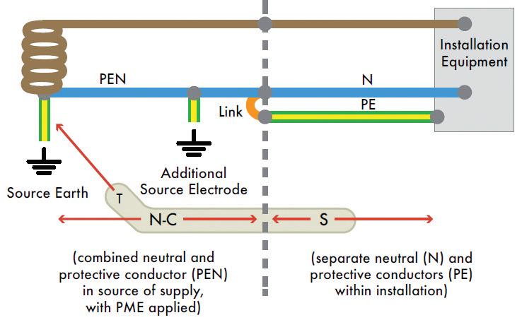
Protective equipotential bonding in these properties may be specified to an older version of BS 7671, therefore may not have been upgraded as BS 7671 has evolved
TN-C-S earthing systems, also known as PME, were first introduced in the early 1970s and are known as Combined Neutral and Earth (CNE) systems by DNO network operators Prior to this, Separate Neutral and Earth (SNE) DNO networks were universal However, over time, many legacy SNE networks have been modified to PME or made PME-enabled
Older properties are also more likely to have metallic water services and therefore provide a more supportive environment for NCD.
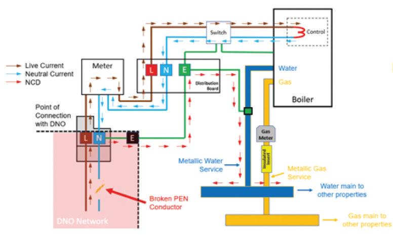
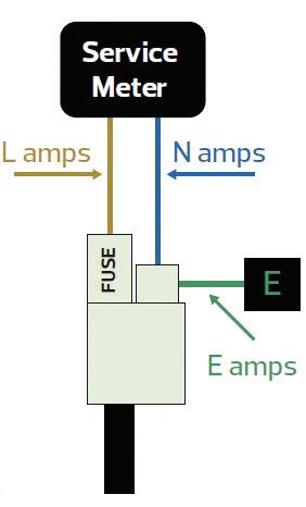
Consequently, the smaller crosssectional area (CSA) of protective bonding conductors in older properties may not be suitably sized for PME conditions, and therefore not rated to withstand the levels of NCD that can occur in a PME network
Some relatively low NCD is a ‘normal’ condition that has been on networks for several decades It’s only really of concern when a broken neutral or high impedance neutral fault occurs on the PEN conductor on PME networks
The IET, ECA, Electrical Safety First, NAPIT, NICEIC and SELECT are working together to investigate the prevalence of Neutral Current Diversion (NCD) incidents across the UK
As an electrical installer, you’re in the perfect position to provide vital information. If you encounter any incidents of NCD, please complete the survey on the IET website, which will take less than five minutes
Before working on an existing electrical installation, it is recommended that the following safety check is carried out to determine the possibility of neutral current diversion (NCD):
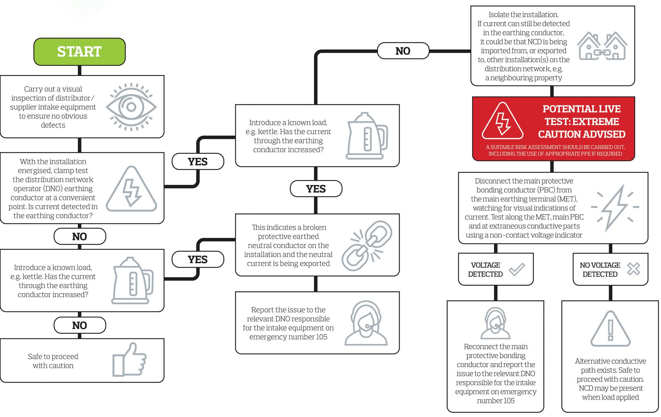
THIS
When we consider the installation of socket- outlets we have to look at Regulation 411 3 3 which lays out the additional requirements for socket- outlets and mobile equipment for use outdoors
Previously under BS 7671:2018 there was an exception to carr y out a risk assessment for anything other than a dwelling, but since BS 7671:2018+A2:2022 the criteria for the risk assessment has altered BS 7671 requires RCD protection for socket- outlets not exceeding 32 A locations liable to be used by children, ordinar y or disabled persons, other locations or for use outdoors.
The risk assessment is only applicable for other locations, but as this is a business premises and those work ing are not considered to be electrically sk illed or instructed persons, therefore the risk assessment exception would not apply.
In the case of carr ying out periodic inspection and testing on these premises the absence of RCD protection for a 32 A socket- outlet single or three -phase in a position where it can be used outdoors, as it is in a location at a roller shutter door, would result in a non- compliance that may give rise to danger
Therefore, the classification code would be a C2, Potentially dangerous, urgent remedial action required due to the lack of additional protection for children, ordinar y or disabled persons. If the socket- outlet could only be used indoors then it would be a C3 improvement recommended
Updated for BS 7671:2018+A2:2022, NAPIT ’s EICR Codebreakers publication is purpose -written to aid contractors, inspectors and clients, and now includes updates to align with Amendment 2 of the IE T 18th Edition Wiring Regulations The book is the per fect technical aid for electrical professionals and their customers.
Need help with cracking those all-impor tant EICR codes? Ever y month the technical team at NAPIT will be studying your latest ‘Caught on Camera’ photos and offering advice on the next steps, should you find a similar installation. If you want the team at NAPIT to help crack your codes then send your pic tures through to us at: pe@hamer ville.co.uk
These ex tension lead connec tions were discovered dur ing per iodic inspec tion and testing. Str ic tly speak ing, por table appliances and flexible cables connec ted via plugs are not par t of the elec tr ical installation that is gover ned by BS 7671
Obviously, the means of connec tion to the ex ter nal socket- outlet utilising a multi-way adaptor is preventing the cover IP rated socket- outlet from being closed to remove the effec ts of moisture or water penetration. Fur ther complications ar ise by utilising an ex tension lead which is not suitable for ex ter nal use
The client quer y about the installation tr ipping when it rains shows a lack of understanding of basic elec tr ical safet y
The area of concer n when having these t ypes of equipment plugged into the elec tr ical installation is that they are por table and may not be connec ted or in place when the per iodic inspec tion and testing is car r ied out As a result, they ’re at r isk of not being discovered
Therefore, the classification code would be a C 2 , Po ten t ia l ly da nge rou s, u rg e nt re m e d ia l a c ti o n req ui red due to the lack protec tion for elec tr ical equipment connec ted to the elec tr ical installation
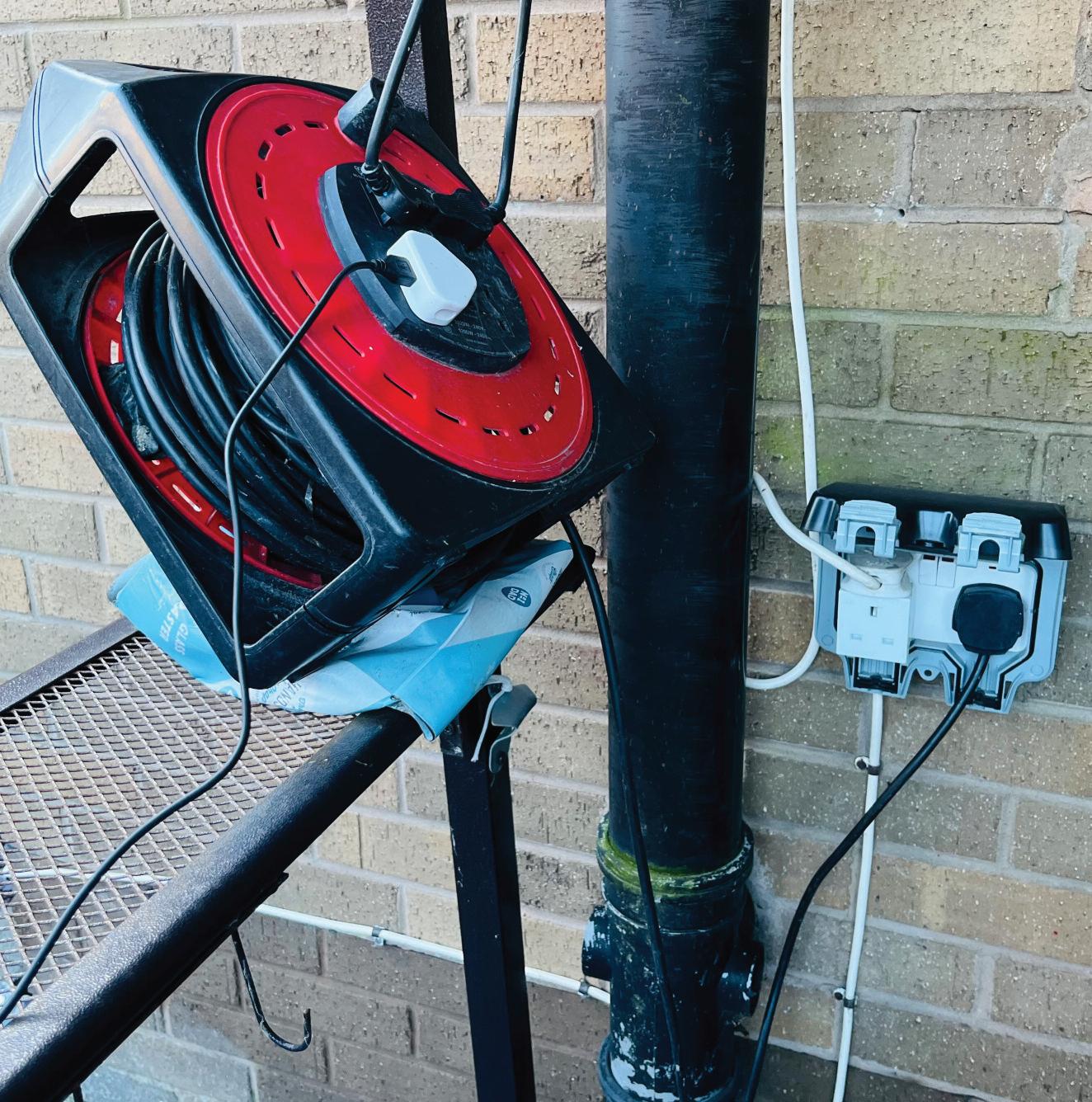
The A2:2022 18th Edition Codebreakers publication is priced at £22.00 (members) and £24.00 (non-members). It is available in both hard copy and digital versions * Price is VAT exempt and excludes postage and packaging.

IN THIS REGULAR COLUMN, DR. TOM BROOKES, MD AT ZZEUS TRAINING AND CHAIRMAN OF THE FSA, ANSWERS YOUR QUESTIONS RELATED TO FIRE SAFETY. IN THIS EDITION HE LOOKS AT SOME OF THE CHANGES THAT WILL BE INTRODUCED AS PART OF THE NEW FIRE ALARM STANDARD.
In the draft for public comments, I noticed that the new 2025 fire alarm standard BS 5839-1:2025, which was due for release in April, has changed the competency clause. Is this to be in line with the BAFE Scheme?
In short, yes, the competency clause has changed. The new standard should have arrived at the end of April and contains several changes There are too many changes to list them all here, but I will highlight a few of them:
Clause 3 13: competent person
Person, suitably trained and qualified by knowledge and practical experience, and provided with the necessary instructions, to enable the required task(s) to be carried out correctly.
Note: Maintenance of competence is likely to require continuing professional development (CPD)
(Source: BS 9991:2024, 3 4, modified –note added)
This is represents a big step forward, and I would like to thank Will Lloyd, the FIA's Technical Manager, for his support in making this change a standard.
So now, in line with BS 9991 Fire safety in the design, management and use of residential buildings, BS 5839-1:2025 has a beefed-up competence requirement
The first part is that you must be suitably trained, so training is required on the current standard, equipment being used, wiring considerations for installers etc.
Next, you will be qualified by knowledge and practical experience
This is important, as you must prove your theoretical knowledge (training and qualifications) and practical experience.
You should also be provided with the necessary instructions to enable the required task(s) to be carried out correctly. These will take the form of equipment instructions, standards, design specs, drawings, etc , to enable you to design, install, and commission a fire system to the latest standards. The critical word here is ‘correctly’
Finally, the note states that you will need to complete CPD hours to maintain your competence.
So, in reality, you are now going to have to prove the aforementioned items to be classed as a competent fire system technician
I feel that a couple of points in the ‘Use of this document’ section are worthy of mention It states that it is a code of practice and that ‘Users are expected to ensure that Claims of compliance are not misleading’
In a nutshell, if you state that it fully meets BS 5839-1:2025 category 2, it should meet every recommendation unless you state a variation
In this section, we assume that the users of this standard will be appropriately qualified and competent people. This means that if you’re to use this standard to install or maintain a fire system, you


should have qualifications in fire alarm and detection and be competent
In scope, it states that this standard doesn’t cover temporary fire detection and fire alarm systems So, if you’re installing any temporary fire alarm system, you can’t claim it meets BS 5839-1:2025.
Clause 6 6 states that three things now should not be allowed as a variation to exclude from your system –where there is more than one storey, particularly where people sleep
a) A zone plan or suitable diagrammatic representation is allowed in clause 22 2 5
b) The absence of an ARC connection in supported housing or residential care homes
Clause 7 9 no longer allows stairway lobbies to be areas of low risk, so they will now need detection
Clause 14.2.2 recommends that if your system is connected to an ARC, a label should be placed on the front of the panel stating so, with a contact number provided
Please note that this article was written before official publication of the standatd
As a result, some of the highlighted items could be changed if there was any legal challenge before the release date


This article from the experts at NICEIC looks at the requirements of Section 710 of BS 7671 for electrical installations in medical locations, and in particular, considers the requirements for the protection against electric shock in such types of environments.
This article focuses on the requirements for shock protection, including the requirements for the protective measure of Automatic Disconnection of Supply (ADS) that are in addition to the general requirements in Section 411.
The requirements for SELV and PELV and additional protection by supplementary bonding in a medical location will also be considered
Shock protection
Like many other types of installations considered in Part 7, the protective
measures of obstacles and placing out of reach are not permitted in medical locations (710 410 3 5)
Likewise, the protective measures of non-conducting location, earth-free equipotential bonding and electrical separation for more than one item of current-using equipment shall not be used (710.410.3.6).
It should be noted that while medical IT systems offer additional protection against first fault conditions, such use of electrical separation is not intended as the sole means of protection against electric shock (see note to 710.410.3.6). The medical IT
system also provides supply reliability. Additionally, only protection by insulation of live parts, or by the use of Class II equipment are permitted
Automatic disconnection in case of a fault
The risks associated with an electric shock due to contact with both AC and DC currents and the subsequent effects on the human body under fault conditions are generally well understood (BS IEC 60479-1) Such that, the average body impedance can be assumed to be around 2 kΩ in a typical environment.
This value will differ between person to person and is influenced by additional factors such as voltage, frequency, skin wetness, physical contact area and duration of current flow.
However, in Groups 1 and 2 medical locations where ME e q u i p m e n t i s u s e d
a n d w h e r e t h e n a t u r a l p r o t e c t i o n o f
t h e h u m a n b o d y i s e x p e c t e d t o b e
r e d u c e d b y f a c t o r s s u c h a s c u t s o r
b r o ke n s k i n , t h i s i m p e d a n c e v a l u e
t e n d s t o b e m u c h l o w e r a n d i s
a s s u m e d t o b e 1 k Ω ( BS EN 60601-1 ) ,
f u r t h e r i n c r e a s i n g t h e v u l n e r a b i l i t y o f
p a t i e n t s t o t h e r i s k s o f e l e c t r i c s h o c k
A d d i t i o n a l l y, t h e p a t i e n t ’s d e f e n s i v e
c a p a b i l i t y m a y a l s o h a v e b e e n
r e d u c e d b y t h e e f f e c t s o f m e d i c a t i o n
o r a n a e s t h e s i a
F o r t h i s r e a s o n , r e g u l a t i o n
7 1 0 4 1 1 3 2 5 r e q u i r e s a r e d u c t i o n i n
t h e c o n v e n t i o n a l m a x i m u m t o u c h
v o l t a g e f r o m 5 0 V, t o 2 5 V AC a n d
6 0 V D C b e t w e e n s i m u l t a n e o u s l y
a c c e s s i b l e e x p o s e d - c o n d u c t i v e - p a r t s
a n d / o r e x t r a n e o u s - c o n d u c t i v e - p a r t s i n
G r o u p 1 a n d 2 l o c a t i o n s w h e n
s u p p l i e d f r o m T N , T T a n d I T s y s t e m s
T h i s m a y b e a c h i e v e d b y t h e p r o v i s i o n
o f s u p p l e m e n t a r y b o n d i n g , w h i c h i s
c o n s i d e r e d l a t e r i n t h e a r t i c l e
A d d i t i o n a l p r o t e c t i o n b y R C D s
I n a T N s y s t e m , R C D s h a v i n g t h e
c h a r a c t e r i s t i c s s p e c i f i e d i n r e g u l a t i o n
4 1 5 1 1 s h a l l b e u s e d t o p r o v i d e additional protection for final circuits in:
● G r o u p 1 m e d i c a l l o c a t i o n s , w i t h a
r a t e d c u r r e n t u p t o a n d i n c l u d i n g
3 2 A , a n d
● G r o u p 2 m e d i c a l l o c a t i o n s , e xc e p t
f o r t h o s e c i r c u i t s s u p p l i e d b y a
m e d i c a l I T s y s t e m a s s p e c i f i e d i n
7 1 0. 4 1 1 .6 .
H o w e v e r, R C D s m a y a l s o b e u s e d o n
f i n a l c i r c u i t s r a t e d a b o v e 3 2 A
e m p l o y e d i n G r o u p 1 l o c a t i o n s
( 7 1 0 4 1 1 4 )
W h e r e m e d i c a l l o c a t i o n s o f a
G r o u p 1 a n d 2 c l a s s i f i c a t i o n a r e
s u p p l i e d f r o m a T T s y s t e m e a r t h i n g
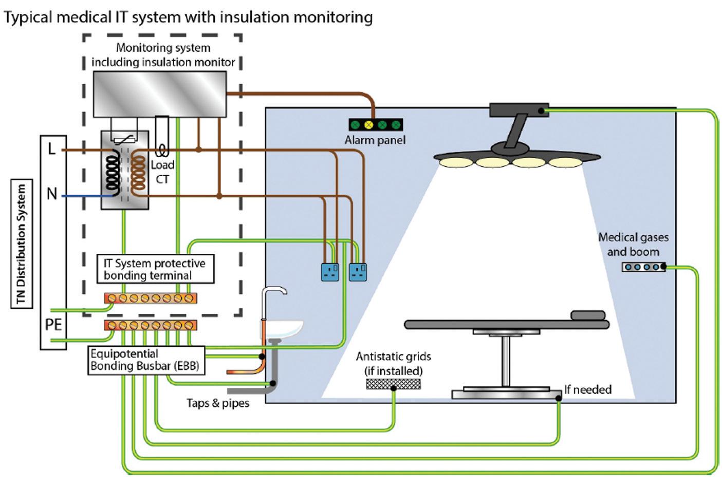
F ig 1 Ex a m p le o f a m e di c a l IT s y s t e m a n d s u p p le m e nt a r y p r o t e c t i v e bo nd i ng us e d in a Gr o up 2 m e di c a l lo ca t io n
a r r a n g e m e n t , r e g u l a t i o n s 7 1 0 4 1 1 5
a n d 7 1 0 4 1 5 1 r e q u i r e t h a t R C D s s h a l l
b e u s e d a s t h e p r o t e c t i v e d e v i c e s f o r
f i n a l c i r c u i t s , e xc e p t w h e r e t h e s e
c i r c u i t s a r e s u p p l i e d f r o m a n I T s y s t e m
s p e c i f i e d i n r e g u l a t i o n 7 1 0 4 1 1 6
W h e r e R C D s a r e r e q u i r e d i n G r o u p
1 a n d 2 m e d i c a l l o c a t i o n s , a n d
d e p e n d i n g o n t h e f a u l t c h a r a c t e r i s t i c s ,
o n l y Ty p e A i n a c c o r d a n c e w i t h BS EN
61008 o r BS EN 61009 , o r Ty p e B o r
Ty p e F t o BS EN 62423 s h a l l b e u s e d
T h e u s e o f Ty p e AC R C D s i s n o t
p e r m i t t e d ( 7 1 0. 5 3 1 . 3 ) .
E x t r a - l o w v o l t a g e p r o v i d e d b y S E LV
o r P E LV
W h e r e S E LV a n d / o r P E LV i s u s e d
w i t h i n s u c h l o c a t i o n s , t h e n o m i n a l
v o l t a g e s u p p l y i n g c u r r e n t - u s i n g
e q u i p m e n t s h o u l d n o t e xc e e d 2 5 V
AC r m s o r 6 0 V r i p p l e - f r e e D C
A d d i t i o n a l l y, p r o t e c t i o n b y b a s i c
i n s u l a t i o n o f l i v e p a r t s , o r a l t e r n a t i v e l y
p r o t e c t i o n b y b a r r i e r s o r e n c l o s u r e s
a s r e q u i r e d b y r e g u l a t i o n 4 1 6 1 a n d
4 1 6 . 2 r e s p e c t i v e l y s h a l l b e p r o v i d e d
( 7 1 0. 4 1 4 .1 ) .
W h e n u s i n g S E LV a n d / o r P E LV
c i r c u i t s i n G r o u p 1 a n d 2 m e d i c a l l o c a t i o n s , a s o u r c e a s d e s c r i b e d i n
r e g u l a t i o n 4 1 4 3 ( i v ) s h o u l d n o t b e
u s e d ( 7 1 0 4 1 4 3 )
F u r t h e r m o r e, w h e r e P E LV i s u s e d i n
a G r o u p 2 l o c a t i o n , f o r e x a m p l e t o
“The
number of connection points required shall be determined by the designer in consultation with the end user.”
s u p p l y t h e t h e a t r e l u m i n a i r e s , a n y
e x p o s e d - c o n d u c t i v e - p a r t s o f s u c h
e q u i p m e n t s h o u l d b e c o n n e c t e d t o
t h e c i r c u i t p r o t e c t i v e c o n d u c t o r
( 7 1 0 4 1 4 4 1 )
A d d i t i o n a l p r o t e c t i o n b y
s u p p l e m e n t a r y p r o t e c t i v e
e q u i p o t e n t i a l b o n d i n g
Re g u l a t i o n 7 1 0 4 1 5 2 1 r e q u i r e s t h a t
s u p p l e m e n t a r y p r o t e c t i v e
e q u i p o t e n t i a l b o n d i n g i s i n s t a l l e d i n
G r o u p 1 a n d 2 m e d i c a l l o c a t i o n s
T h e p u r p o s e o f s u c h p r o t e c t i v e
b o n d i n g i s t o p r o v i d e a d d i t i o n a l p r o t e c t i o n a g a i n s t e l e c t r i c s h o c k b y
l i m i t i n g t h e m a g n i t u d e o f t o u c h
v o l t a g e s d u r i n g a f a u l t
T h e s u p p l e m e n t a r y b o n d i n g
c o n d u c t o r s s h a l l b e c o n n e c t e d t o t h e
E q u i p o t e n t i a l B o n d i n g B u s b a r ( E B B ) t o
f a c i l i t a t e t h e e q u a l i s a t i o n o f p o t e n t i a l
d i f f e r e n c e s b e t w e e n t h o s e s p e c i f i c
p a r t s a s l i s t e d i n i n d e n t s ( i ) t o ( v ) i n
r e g u l a t i o n 7 1 0 4 1 5 2 1 t h a t a r e l o c a t e d ,
o r t h a t m a y b e m o v e d i n t o, t h e p a t i e n t
e n v i r o n m e n t .
F o r t h i s r e a s o n , s u p p l e m e n t a r y
b o n d i n g c o n n e c t i o n p o i n t s s h a l l b e
m a d e a v a i l a b l e f o r M E e q u i p m e n t
u s e d i n G r o u p 2 l o c a t i o n s , a n d
s i m i l a r l y, s h o u l d a l s o b e c o n s i d e r e d
f o r G r o u p 1 m e d i c a l l o c a t i o n s
T h e n u m b e r o f c o n n e c t i o n p o i n t s
r e q u i r e d s h a l l b e d e t e r m i n e d b y t h e
d e s i g n e r i n c o n s u l t a t i o n w i t h t h e e n d
u s e r H o w e v e r, N o t e 1 t o r e g u l a t i o n
7 1 0 4 1 5 2 1 r e c o m m e n d s t h a t :
● I n G r o u p 1 m e d i c a l l o c a t i o n s –a
m i n i m u m o f o n e s u p p l e m e n t a r y
b o n d i n g c o n n e c t i o n p e r p a t i e n t
l o c a t i o n i s p r o v i d e d , a n d
● I n G r o u p 2 m e d i c a l l o c a t i o n s –a
m i n i m u m o f f o u r s u p p l e m e n t a r y
b o n d i n g c o n n e c t i o n p o i n t s b u t n o t
l e s s t h a n 2 5 % o f t h e t o t a l n u m b e r
o f i n d i v i d u a l m e d i c a l I T
s o c ke t - o u t l e t s i s p r o v i d e d p e r
p a t i e n t l o c a t i o n
P r o t e c t i v e c o n d u c t o r s i n G r o u p 1 a n d
2 m e d i c a l l o c a t i o n s m u s t b e c o r r e c t l y
s i z e d a n d a r r a n g e d s o t h a t t h e i r
r e s i s t a n c e d o e s n o t e xc e e d 0 2 Ω
( 7 1 0 4 1 5 2 2 )
T h e r e s i s t a n c e b e t w e e n t h e
p r o t e c t i v e c o n d u c t o r s a n d t h e e a r t h
t e r m i n a l o f a n y s o c ke t - o u t l e t ( o r f i xe d e q u i p m
e x t r a n e o u s - c o n d u c t i v e - p
( c s a ) o f a s u p p l e m e n t a r y b o n d i n g
c o n d u c t o r m u s t b e a t l e a s t t h a t
r e q u i r e d b y r e g u l a t i o n G r o u p 5 4 4 2
Section 710 recognises that, in some cases, supplementary bonding conductors installed in loops can lead to electromagnetic interference (EMI) due to the presence of circulating currents and may affect some types of sensitive electrical ME equipment (710 444)
To m i t i g a t e a n y p o t e n t i a l i s s u e s i n
G r o u p 1 a n d 2 m e d i c a l l o c a t i o n s , N o t e
2 t o r e g u l a t i o n 7 1 0 4 1 5 2 3
r e c o m m e n d s t h a t r a d i a l w i r i n g
p a t t e r n s a r e u s e d t o a v o i d s u c h ‘ e a r t h
l o o p s’ t h a t m a y i n t e n s i f y s u c h
e l e c t r o m a g n e
E q u i p o t e n t i a l b o n d i n g b u s b a r ( E B B )
All supplementary bonding conductors should be connected individually to the EBB (see Fig 2), which in addition, must be made readily accessible and located in or near1 each medical location in which it serves (see Fig 1)
T h e E B B s h o u l d b e c o n n e c t e d t o
t h e m e a n s o f e a r t h i n g f o r t h e
i n s t a l l a t i o n w i t h a p r o t e c t i v e
c o n d u c t o r h a v i n g a c r o s s - s e c t i o n a l
a r e a ( c s a ) g r e a t e r t h a n o r e q u a l t o t h e
l a r g e s t c s a o f a n y c o n d u c t o r
c o n n e c t e d t o t h e E B B
A l l c o n n e c t i o n s s h a l l b e c l e a r l y
v i s i b l e, i d e n t i f i e d a n d s o a r r a n g e d t o
e n a b l e b o n d i n g c o n d u c t o r s t o b e
i n d i v i d u a l l y d i s c o n n e c t e d
( 7 1 0 4 1 5 2 3 )
W h e n i n s t a l l i n g t h e E B B , c o n s i d e r a t i o n s h o u l d b e g i v e n t o
m e e t i n g t h e l o c a l i n f e c t i o n p r e v e n t i o n a n d c o n t r o l r e q u i r e m e n t s f o r s u c h
t y p e s o f l o c a t i o n
T h e E B B s h o u l d b e c o n t a i n e d i n a
s u i t a b l e e n c l o s u r e a n d n o t b e
i n s t a l l e d i n a c e i l i n g v o i d w h e r e, f o r
e x a m p l e, d u r i n g a n i n s p e c t i o n , f a l l i n g
d e b r i s d u e t o t h e r e m o v a l o f a c e i l i n g
t i l e m a y l i ke l y i n c r e a s e i n f e c t i o n r i s k
( 7 1 0 4 1 5 2 3 )
S u m m a r y
T h i s a r t i c l e h a s f o c u s e d o n t h e
r e q u i r e m e n t s f o r s h o c k p r o t e c t i o n i n
G r o u p 1 a n d 2 m e d i c a l l o c a t i o n s a n d
c o n s i d e r e d t h e n e c e s s a r y p r e c a u t i o n s
t o p r e v e n t a n i n c r e a s e d r i s k o f e l e c t r i c
s h o c k t o v u l n e r a b l e p a t i e n t s w i t h i n
s u c h t y p e s o f e n v i r o n m e n t s
We would like to acknowledge and thank Brandon Medical for providing some of the images used within this article.
1 It is generally considered that near to the medical location would mean directly outside of the room containing the respective patient environment
As the 2025 deadline for electrical safety checks in the Private Rented Sector (PRS) fast approaches, Frank Bertie, Managing Director at NAPIT, outlines the key responsibilities to ensure tenant safety and legal adherence.
Landlords in the PRS are being reminded of the upcoming deadline for the next round of electrical safety checks The original regulations, introduced in 2020, require regular inspections to ensure the safety of tenants
The intention of the government was to improve the electrical safety standards of the Private Rented Sector, which up until then had been lacking in detailed requirements for landlords to carry out electrical inspections
The 2020 legislation requires landlords to ensure electrical safety checks in new tenancies from 1st July 2020 and existing tenancies from 1st April 2021, as shown in Fig 1
As we move through 2025, the five-yearly inspections are fast approaching (see Fig 2)
Qualified and competent tradespeople
It’s essential that only qualified and experienced professionals carry out electrical inspections A competent person is someone with the required qualifications, skills and experience to carry out the particular task.

They upgrade those attributes when new ways of working and changes to relevant regulations dictate any requirements for Continuing Professional Development (CPD)
Simply having the necessary qualifications is not enough; inspectors must have practical experience to carry out the complex tasks required from them during an electrical safety check or Electrical Installation Condition Report (EICR) This ensures they can identify any risks or issues accurately
It’s essential that only adequately qualified, experienced, skilled and monitored Inspectors are engaged in the inspection and any testing of dwellings, in accordance with the PRS legislation
From an industry skills perspective, the requirements for inspection, testing, verification and certification, of even new installations, are seen as a highly-skilled job, due to the extensive knowledge of BS 7671 needed, which can only be gained through

experience. Fig 3 details the requirements for a qualified and competent person
Landlord considerations
Landlords should confirm the Inspector’s qualifications and competency before engaging their services.
The Inspection and Testing shall follow BS 7671 Wiring Regulations and use the EICR to record the findings of the electrical safety check
The PSR regulations require the landlord to obtain ‘a report’ – this may be the full EICR or a report of its findings, provided it gives the results of the Inspection and Testing and quotes the date of the next inspection
Landlords must ensure they’re in possession of the previous EICR to provide to the person carrying out the next due electrical safety check. This will assist the information regarding the extent of the electrical installation contained in the previous EICR

There have been no changes to the original legislation laid out in 2020, therefore all the requirements that landlords had to comply with will remain the same for the next electrical safety checks
When the new EICR is received by the landlord they must:
● Supply a copy to each existing tenant within 28 days of the inspection and testing.
● If requested in writing to do so, supply a copy to the local housing authority within seven days of such a request
Note that it isn’t a requirement to inform the local authority of every report
● Keep a copy of the report at least until the next inspection
● Provide a copy of the report to the person carrying out the next inspection
● Provide a copy of the report to any new tenant moving into the property, before they take up occupation
● If requested in writing to do so, supply a copy to a prospective tenant within 28 days of a request
An Unsatisfactory EICR highlights there are requirements for further investigations or rectifications. Any such work must be carried out by a qualified, competent person
Written confirmation of the rectification works being carried out must be obtained from them with any remedial works or further investigations documented, using adequately appropriate forms, those being the Electrical Installation Certificate (EIC) and for lesser work, the Minor Electrical Installation Works Certificate (MEIWC), as defined by BS 7671
It should be noted that any remedial work may also be notifiable and

governed by Building Regulations, specifically Approved Document P (England), which covers electrical safety in dwellings.
Any documentation regarding further investigation or remedial work carried out must be supplied to the tenant within 28 days and the local housing authority
Where this highlights further required works, the landlord must again present this information to the tenant within 28 days and local housing authority, and when the works are complete and acceptable, a further 28 days limit to supply the tenant and local housing authority with the acceptable documentation will be enforced.
1 Check inspection dates
Review the dates of previous inspections and ensure the next one is scheduled before the deadline.
2 Confirm inspector qualifications
Only hire qualified professionals with the required experience
3 Complete and distribute reports
Ensure all required reports are provided to tenants and authorities promptly
Landlords are legally required to carry out electrical safety checks and maintain proper documentation in line with the 2020 PRS regulations; it’s important to remember that anyone conducting EICRs for the Private Rented Sector has to demonstrate their qualifications and competence.
The 2025 deadline is fast approaching, and compliance ensures the safety of tenants and the continued legality of rental properties
Chaz Andrews, Technical Manager at Doepke UK, looks into the requirements for Type B RCD use in Heat Pump installations, following Amendment 3 to BS 7671.
Heat Pumps (HP) producing leakage currents above 1 kHz, will not be compatible with Type B RCDs that are only manufactured to meet the lowest requirement of BS EN 62423, i e operation up to 1 kHz
Type B RCDs rated for use up to 1 kHz may trip unexpectedly when subjected to leakage currents above 1 kHz, or worse, the detection circuit may be saturated (blinded) This will result in the device not detecting residual currents under fault conditions
BS 7671 offers essential guidance for the installation design for those who have the experience to ask the right questions If unsure, the “skilled person” will seek the advice of the HP and RCD manufacturers, to verify that the characteristics of the equipment they intend to use are compatible.
134.1.1 “The installation of electrical equipment shall take account of manufacturers’ instructions”
The Domestic Heat Pump Safety Standard BS EN 60335-2-40: 2024+A112024 advises that manufacturers state in their instructions the use of 30 mA RCD protection for equipment that is permanently connected to fixed wiring Check the manufacturers’ instructions relating to specification requirements for RCD protection
Modern HPs contain larger inverters, the characteristics of which must be considered when designing the installation Installers who have not been involved in commercial or industrial applications may not have had experience with this type of equipment or the application of Type B RCDs
Leakage current in AC circuits is an
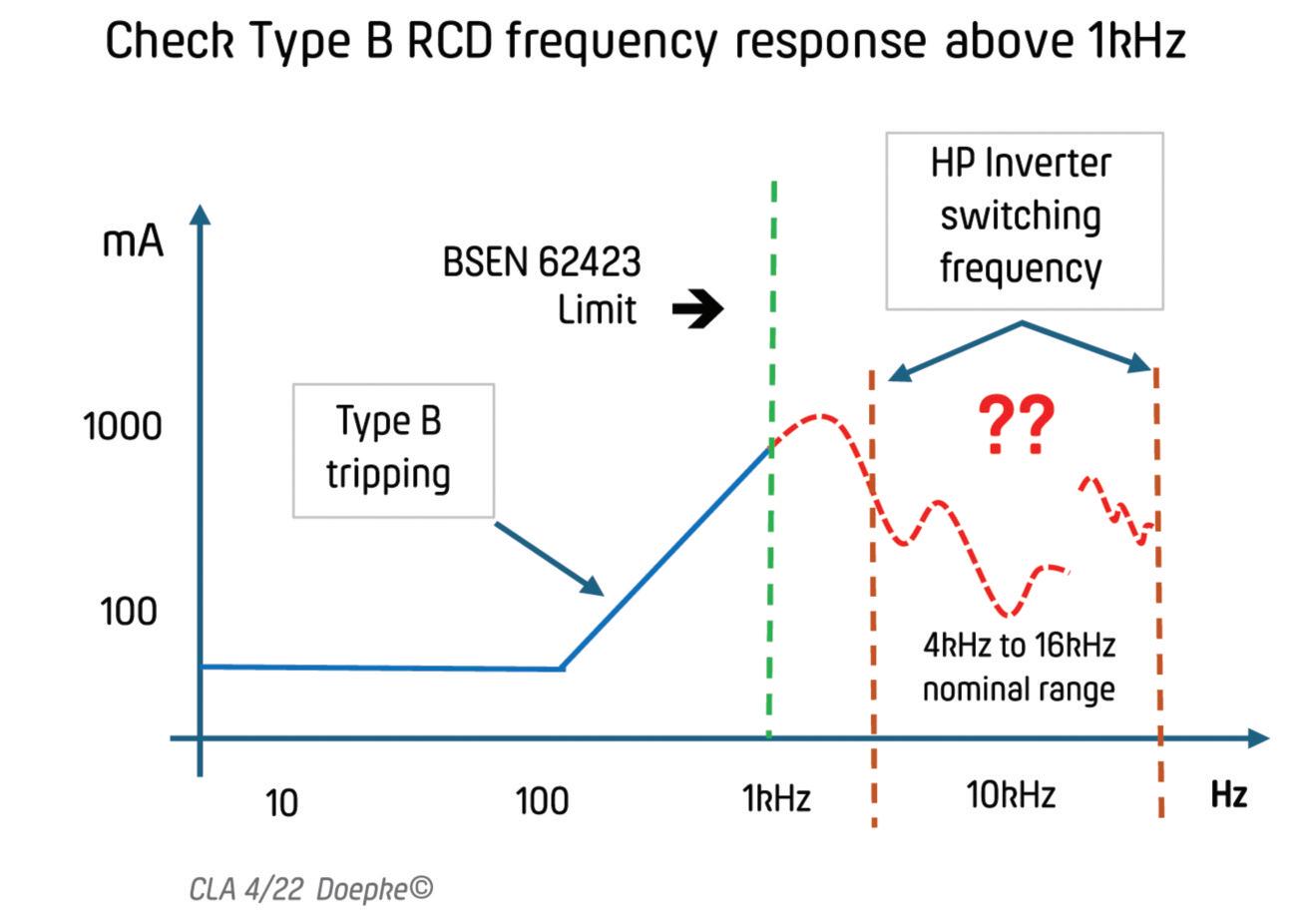
inherent function of circuit capacitance and increases as a function of frequency
Modern HPs, to improve efficiency, apply inverter technology with switching frequencies in the kHz range HP leakage current and the associated harmonic currents must not have a detrimental effect on the protection offered by the RCD, and the RCD should not trip due to normal circuit leakage current
Understanding the standards
At the time of writing, BS 7671 Appendix 1 refers to BS EN 62423 2012 for Type B: To claim compliance, RCDs do not have to work above 1 kHz. The VDE standard 0664-400 (B+) sets an upper limit of 20 kHz *
This is a recognised issue for larger inverter applications, usually associated with non-domestic installations Doepke and several European manufacturers’ Type B RCDs exceed the requirements of the existing BSEN standard and the VDE

standard Consequently, for applications exceeding the 1 kHz value (see clause 133 1 1), reference must be made to the individual manufacturer’s Type B RCD characteristics and the HP manufacturer’s instructions, relating to the compatibility of upstream protection devices.
The diagram (pictured above) gives an example of two 30 mA Doepke Type B characteristics for use with Heat Pumps
The red dashed line shows the existing 1 kHz requirement for BS EN 624232 Doepke Type B RCCBs will operate <150 kHz, the graph is truncated at 100 kHz to increase the horizontal axis (readability)
● Grey shaded area: Tripping characteristic for DFS HP and DFS BSK
● Blue line: 20 kHz limit of operation for VDE 0664-400 B+
● Green line: DFS HP operating limit 150 kHz
● HP leakage currents > 20 kHz result from incorrect EMC protection or high supply harmonics
● Example: If 150 mA leakage current at say 4 kHz flows in the circuit, it should not trip the RCD
Greener homes require more innovative solutions (equipment) than those traditionally associated with domestic installations. This involves consideration
“In addition to safety, using inappropriate products in the HP installation will result in system availability problems for the final customer.”
of the characteristics of the equipment we intend to supply with electricity
Manufacturers such as Doepke publish characteristics for their Type B RCCBs; these can be used to verify that they are compatible with the HP model HP manufacturers who do not clearly state RCD compatibility requirements risk costly rework when things go wrong
In addition to safety, using inappropriate products in the HP installation will result in system availability problems for the final customer This, in turn, affects the reputation of the HP brand and the companies involved in the installation
As with any complex equipment, HP characteristics vary from one manufacturer to another Consequently, the design of the electrical supply requirements and associated protection devices may differ. This must be
considered with the individual site design requirements based on BS 7671 and HP manufacturer’s recommendations
* The performance limit for an RCD with regard to frequency, is a function of the quality and properties of the magnetic materials and the design of detection circuits used in the product: Characteristics above 1 kHz are based on extrapolation of the tripping requirements in 62423 and the advice/limits given in IEC60479-2 thresholds < 150 kHz The Doepke 30 mA HP & BSK characteristics are within the threshold limits for ventricular fibrillation < 150 kHz/IEC609479-2
GET MORE DETAILS ABOUT DOEPKE’S FULL PRODUCT OFFERING BY VISITING: WWW.RDR.LINK/EBN018
CLAIM YOUR CERTIFICATE! SCAN THE QR CODE TO CLAIM YOUR CPD CREDIT FOR THIS SECTION OR VISIT: WWW.RDR.LINK/EBN019

To protect cables when they enter a consumer unit we should use appropriate methods, accessories and fittings. This could include rubber or PVC grommets for a simple cable installation to offer the cable protection against sharp metal edges For meter tails this might be a cable entr y gland that has the line, neutral and ear thing conductor installed through the same gland. This would provide secure and sealed protection from damage and external influences.
This installation has a few issues The meter tails have no means of suppor t for the cables and terminations The use of fibre glass wool to prevent abrasion from the sharp metal edges would not offer much in the way of protection. This also would not offer any protection from wires or fingers being pushed through the openings and therefore allowing access to live par ts
One other thing to bear in mind is that the use of fibre glass wool would not increase the protection against the spread of fire
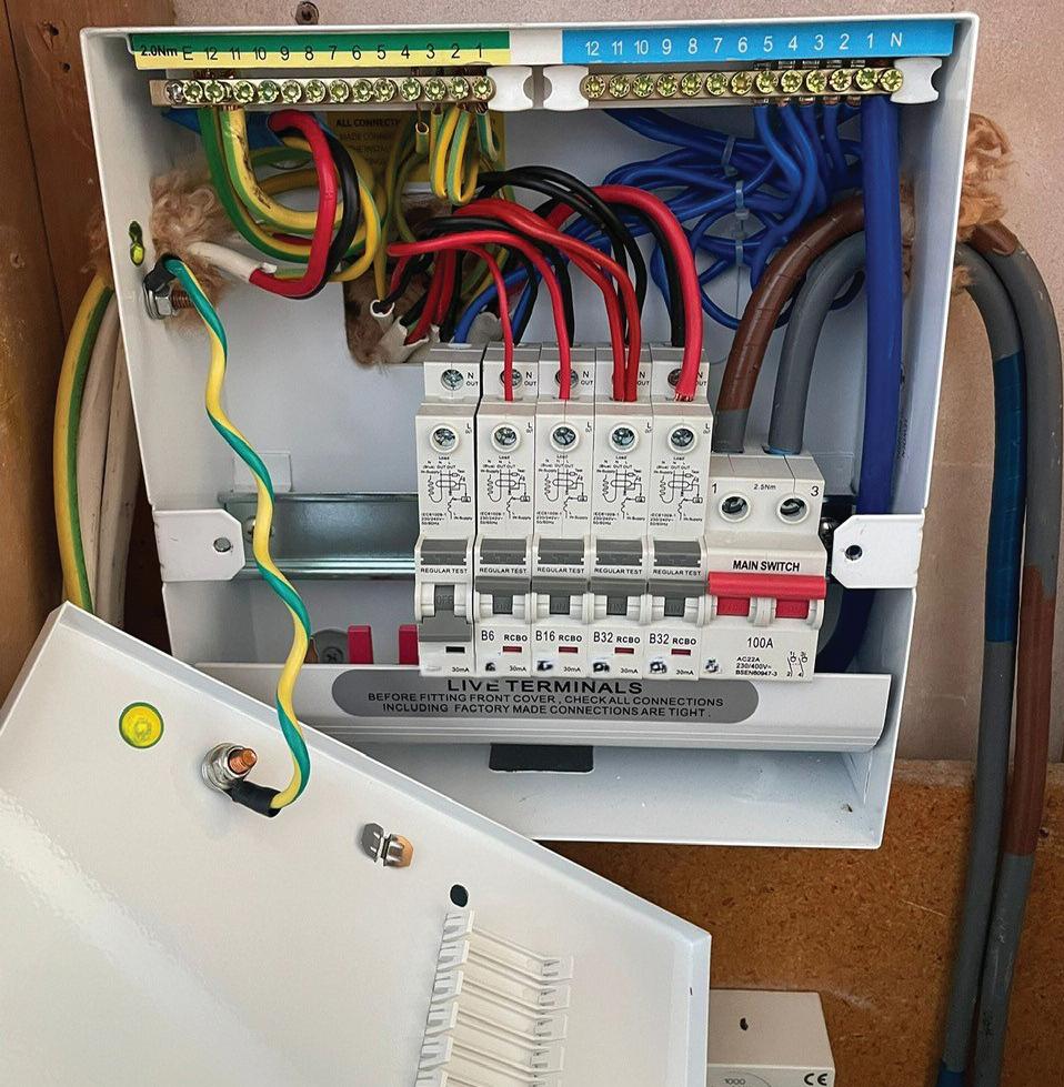
Updated for BS 7671:2018+A2:2022, NAPIT ’s EICR Codebreakers publication is purpose -written to aid contractors, inspectors and clients, and now includes updates to align with Amendment 2 of the IE T 18th Edition Wiring Regulations The book is the per fect technical aid for electrical professionals and their customers.
Need help with cracking those all-impor tant EICR codes? Ever y month the technical team at NAPIT will be studying your latest ‘Caught on Camera’ photos and offering advice on the next steps, should you find a similar installation. If you want the team at NAPIT to help crack your codes then send your pic tures through to us at: pe@hamer ville.co.uk
RICHARD COCKERLINE: HOW DO SOME PEOPLE SLEEP AT NIGHT?
Al te rat i o n s to e l e c t r i c a l i n s t a l l at i o n s a re a co m m o n
o cc u r re n ce, b u t t h e y d o h ave to co m p l y w i t h t h e
re q u i re m e nt s o f B S 7 6 7 1 .
Wi t h t h i s a l te rat i o n , i t a p p e a r s t h e re wa s a
re q u e s t fo r a l o c a l s w i tc h fo r t h e l i g ht f i t t i n g,
re s u l t i n g i n a n u n o r t h o d ox m e t h o d o f te r m i n at i o n
Th i s i s a n o l d e r ve r s i o n o f a p l u g i n l i g ht i n g
s o c k e t, w h e re a 5 A t h re e - p i n p l u g a n d s o c k e t a re
u t i l i s e d fo r l i g ht i n g i n s t a l l at i o n s.
U n fo r t u n ate l y, t h e re h a s b e e n n o t a ny
co n s i d e rat i o n o f e l e c t r i c a l s a fe t y Th e t h re e - p i n p l u g
h a s b e e n d a m a g e d, a l l ow i n g a cce s s to l i ve p a r t s
S i n g l e i n s u l ate d co n d u c to r s h ave n o t b e e n
e n c l o s e d a n d t h e re i s n o s u p p o r t fo r t h e c a b l e s o r
te r m i n at i o n s.
An o t h e r a re a o f co n ce r n wo u l d b e t h e t w i n a n d
e a r t h c a b l e w i t h o n l y t h e l i n e ( re d ) co n d u c to r
co n n e c te d Th i s co u l d m e a n t h at we h ave a
b o r rowe d n e u t ra l i f t h e l i n e co n d u c to r h a s n o t b e e n
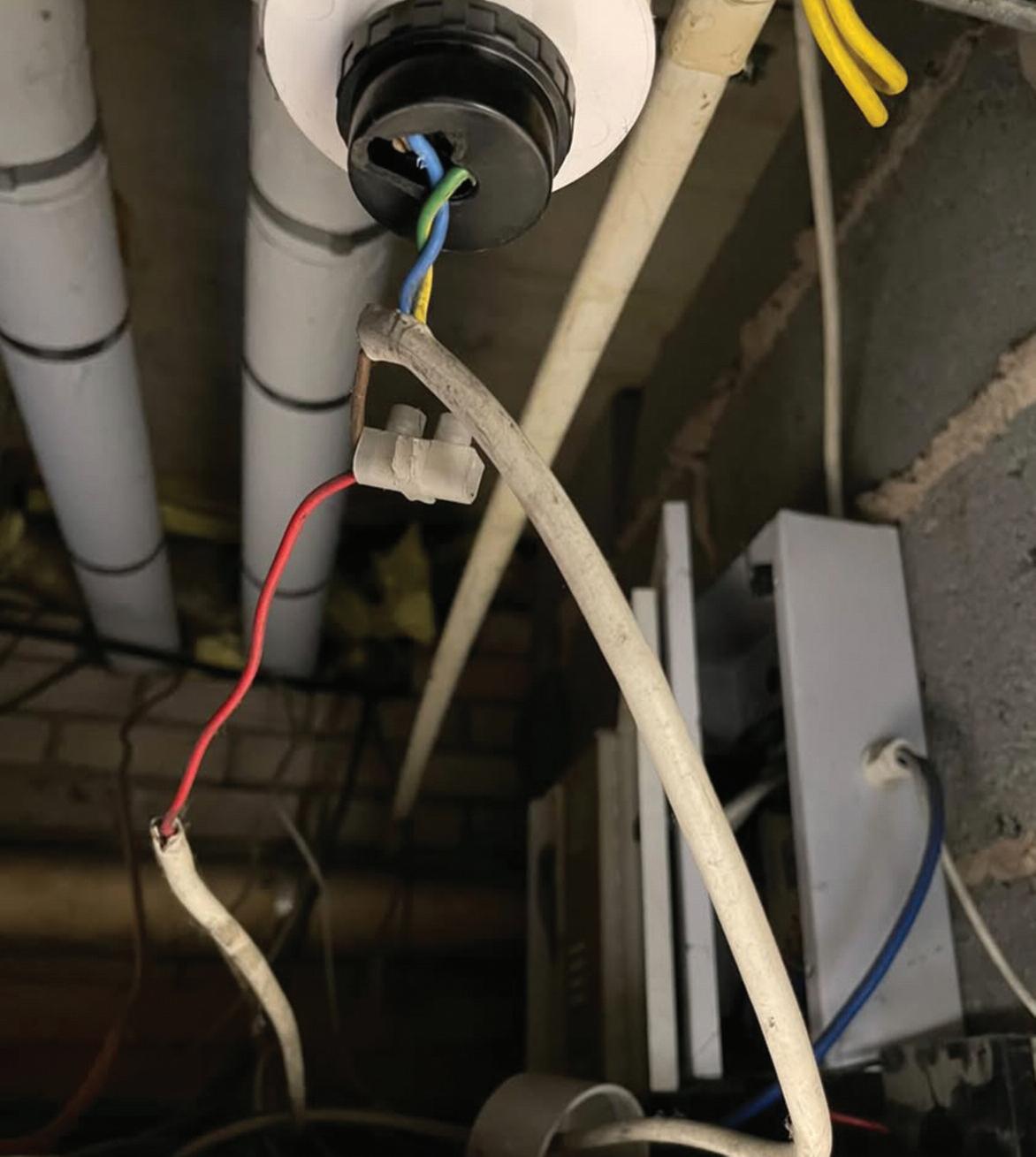
The A2:2022 18th Edition Codebreakers publication is priced at £22.00 (members) and £24.00 (non-members). It is available in both hard copy and digital versions * Price is VAT exempt and excludes postage and packaging.
d e r i ve d f ro m t h e s a m e c i rc u i t ORDER YOUR COPY OF NAPIT CODEBREAKERS BY VISITING: WWW.RDR.LINK/EBO013
In each edition, our team of expert, technical engineers answer essential questions from NICEIC-certified businesses – here are a few of the latest queries.
Who should make the recommendation for the interval to the first periodic inspection and test of a new installation?
The designer
Regulation 134 2 2 states that: “The designer of the installation shall make a recommendation for the interval to the first periodic inspection and test as detailed in Chapter 64.”
It is also noted that the requirements of Chapter 34 (Maintainability) should be taken into consideration
Which of the following is excluded from the scope of BS 7671?
a) prefabricated buildings b) railway signalling equipment c) sauna rooms d) ceiling heating systems
The answer is b) railway signalling equipment
Regulation 110.2 Exclusions From Scope states that: “The Regulations do not apply to the following installations: (ii) Railway traction equipment, rolling stock and signalling equipment”
And Regulation 110 1 1 states that: “The Regulations apply to the design, erection and verification of electrical installations such as those of: (v) prefabricated buildings, (x) rooms and cabins containing sauna heaters, (xxvi) floor and ceiling heating systems”.

In a TT system, can I use just a circuit-breaker to provide protection against electric shock?
Yes
Regulation 411.5.2 states that: “One or more of the following types of protective device shall be used, the former being preferred: (i) An RCD (ii) An overcurrent protective device”.
There is also an informative note which states that: “An appropriate overcurrent protective device may be used for fault protection provided a suitably low value of Zs is permanently and reliably assured”
So, if your Zs has a suitably low value which can be permanently and reliable assured, ensuring that the circuit-breaker will achieve the required disconnection time for protection against electric shock, then you can use a circuit breaker for protection against electric shock in a TT system, without needing an RCD
There is also a second informative note which states that: “Where an RCD is used for fault protection the circuit should also incorporate an overcurrent protective device in accordance with Chapter 43”
In the second of a series of articles aimed at helping you to gain a better understanding of three-phase supplies, Jake Green, Head of Technical Engagement at Scolmore Group, delves into the issue of fault currents.
In any electrical system a fault to Earth or a fault between live conductors will generate a fault current The level of fault current will depend on a range of factors, including voltage levels, number of phases, proximity to the distribution transformer, and the like
This article looks at likely levels of fault current, how they are to be assessed and the nature of equipment being sufficient to manage such fault currents (breaking capacity)
Types of fault
There are two types of ‘short circuit’ generally considered in BS 7671:
● Earth fault current – a current resulting from a fault of negligible impedance between a line conductor and an exposed-conductive-part or a protective conductor
● Short circuit – an overcurrent resulting from a fault of negligible impedance between live conductors having a difference in potential under normal operating conditions
Based on Fig 1 the level of fault current is determined by the following:
● The voltage – single phase (230 V)
● The impedance of the transformer winding
● The impedance of the supply cable (line-to-Earth or line-to-neutral)
● The impedance of the internal cable (line-to-Earth or line-to-neutral).

The simplest way to determine the level of fault current in a single-phase system is to determine the combined values of the transformer winding and the line and neutral conductors.
Based on Fig 1 the level of fault current is determined by the following:
● The voltage – counter-intuitively this is taken to be the value of a single-phase supply (230 V)
● The impedance of the transformer winding
This can be simplified to:
Based on Fig 1 the level of fault current is determined by the following:
● The voltage – between two phases (400 V)
● The impedance of the transformer winding
● The impedance of the supply cable (line-to-Earth or line-to-neutral)
● The impedance of the internal cable (line-to-Earth or line-to-neutral
The simplest way to determine the level of fault current between two-phases is to determine the combined values of the transformer winding and the line and line conductors
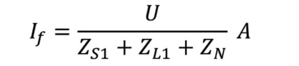
This can be simplified to:
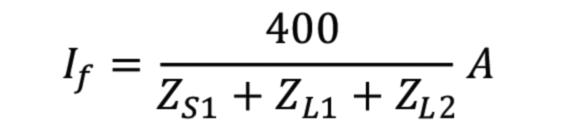
The level of fault will be greater than for a single phase fault but will not be double the value of a single-phase fault.
● The impedance of the supply cable (line only)
The simplest way to determine the level of fault current between three-phases is to determine the combined values of the transformer winding and the line conductor
This can be simplified to:
The level of fault will be greater than for a single-phase fault, and a two-phase fault but will still not be double the value of a single-phase fault.
Understanding the difference between expected fault current levels is important when selecting electrical equipment, such as circuit-breakers, switches and the like
In a subsequent article we will consider the impact of prospective fault current values on the choice of equipment and recognise the importance of ensuring that the correct breaking capacity is selected

Pod Point’s Electrical Compliance Manager, Richard Townsend, provides an insight into what to consider before installing EV charge points.
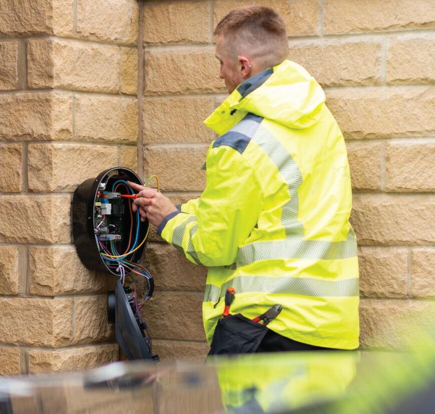
We often receive requests from clients to retrofit EV charge points to an existing infrastructure, replacing their original equipment That sounds like a simple process, almost a one-for-one swap, and in many cases, that’s usually not far off the mark However, there are instances where a direct one-for-one replacement can’t be achieved, so we survey every retrofit case before committing to any such undertakings
Always treat a retrofit as a new installation, surveying the existing infrastructure and equipment to ensure it meets legislative requirements. So, how do we start?
For any installation, always consider the basic BS 7671 requirements:
● Does the supply have capacity for an EV? (301)
● Will it need load management? (722 311 201)
● Are the main live and neutral supply conductors csa adequate? (132.6)
● What is the Earthing arrangement for the incoming supply? (TT, TN-C-S (PME), TN-S) (132 2, 301)
● Is the installation's main earthing conductor csa adequate? (542 3)
● Does the charge point need diverted neutral current protection? (Open Pen) (722 411 4 1 iii, iv, v)
● Does the existing installation have adequate main and supplementary protective bonding in place? (411 3 1 2, 544 1, 544 2)
● Is the supply a looped and, if required, has the DNO been made aware?
● Has the DNO been made aware of the EV equipment install via their notification portal?
These are all basic requirements On top of these, each install also needs to be carefully designed to ensure that it
meets the following requirements:
● Cable current carrying capacity (132 6)
● Has the customer agreed to fitting an SPD? (If not, have they signed a waiver?) (443 4 1)
● Is the capacity of any OCPDs adequate for the load/cable protection? (132 8)
● Are switchgear and enclosures used from the same manufacturer? (536 4 203)
● RCDs or RCBOs must be double-pole and disconnect both live conductors (722 531 3 1)
So, we’ve established that the new or retrofit installation meets the requirements of BS 7671 Does this mean we’re good to go? Not quite There are requirements from multiple legislations that we need to consider before installation. Some things to look out for include:
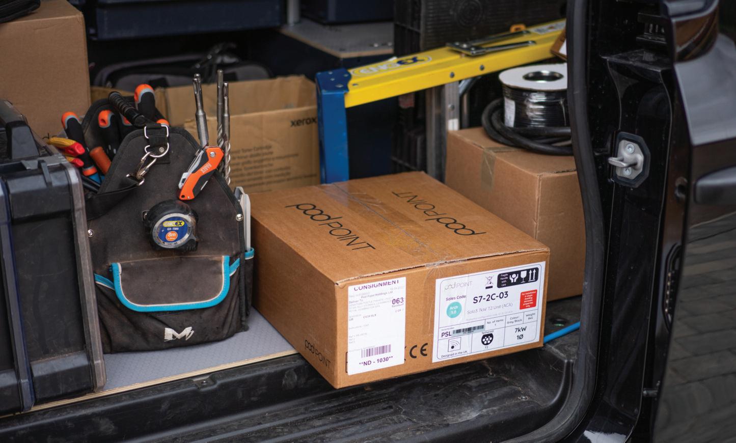
There are strict guidelines for installing in these areas Most will need permission to ensure the resulting EV charge point doesn’t impact the region's natural heritage There may also be requirements placed on the eventual installation
Depending on the level of a property’s category, the likelihood of being able to install will rest on permissions from the local planning authority All properties and areas are unique, with varying compliance requirements
This is possibly the most important consideration for the placement of EV charge points After we’ve addressed everything else, we must ensure that we don’t impact or contravene this Act, which
requires that we don’t allow cables to cross or block public access or paths
Some local authorities are more lenient to this requirement, provided the client takes full responsibility for any such practice They’re all slightly different, so you need to check with the one applicable to where the installation will be
If it’s a new installation, has accessibility been taken into account? Depending on the use of the building or the EV charge point, the height at which the EV charge point has been located and adequate accessible space around the vehicle will need to be assessed. Devolved nations will also have similar requirements
Where parking for a proposed EV charge point is unclear, the land registry details and permission need to be sought from the client to ensure the installation doesn’t cause any ownership or legal issues later on
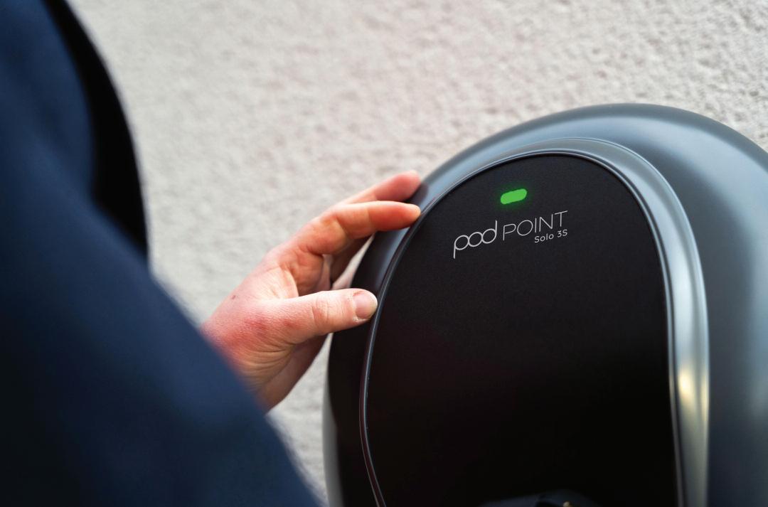
a secluded off-street gravelled area, for example, this can sometimes be seen as ‘custom and practice’ This means that everyone in a particular area parks in a non-designated way, so an EV charge point can be installed
Custom and practice is challenging to confirm, and permissions from neighbours and local authorities must be sourced
Where properties share party walls, or where an allocated parking space is next to them or the boundaries of different properties, always ask for permission to install on a neighbour's wall or property, as this can cause conflicts we want to avoid
Whenever you retrofit, any waste must be disposed of responsibly; never use the customer's refuse facility unless it's clear that the waste is suitable and there is permission to use it The equipment's overall environmental impact and sustainability must be considered, particularly printed circuit boards (PCBs), which are always present in EV charging equipment
Given the considerable power EV charge points can draw, the correct design parameters, including those for retrofit installations, must be met every time.
In addition, non-electrical permissions must be in place prior to any installation
Our advice is to review everything and ask the client for written permission if you feel it’s not a straightforward installation
If you need technical help or advice, please don't hesitate to contact us here at Pod Point We’ll always give you the advice you need, whenever we can Simply email: PodpointPE@pod-point.com
Where parking is not clearly defined, and locals seem to park in a way that doesn’t allow them permission, but everyone does it, in
We’ll also be attending all the remaining ELEX events in 2025 and we frequently visit wholesaler events. Feel free to drop by for free advice and a catch-up
GET MORE DETAILS ABOUT POD POINT’S RANGE OF EV CHARGING EQUIPMENT AND SERVICES BY VISITING: WWW.RDR.LINK/EBO015

Steve
How often have we lifted a lid off a run of trunking to reveal that it is jam-packed with cables with no consideration for its capacity or spacing factors?
Fig 1 shows some cables which are poorly contained
It is quite common for circuits to be added after the initial installation and it is the responsibility of designers and installers to ensure that the containment system is still large enough to accommodate these additional cables
It is essential for an initial installation that the designer selects trunking and conduit systems that are sized correctly so they can comfortably accommodate the
“Fortunately, the IET On-Site Guide Appendix E contains more information regarding cable capacities for trunking and conduit.”

number of circuit conductors required. Failure to do so can result in damage to conductor insulation, especially when drawing the cables into the containment system
Another issue is that there will be an increase in operational temperature when too many cables are installed in trunking or conduit
Common sense tells us that the more cables we have in a containment system, the more heat is generated, which in turn reduces the current carrying capacity of the conductors Therefore, it is extremely important to leave free space, known as a ‘spacing factor’ within the containment system to allow any excess heat to dissipate
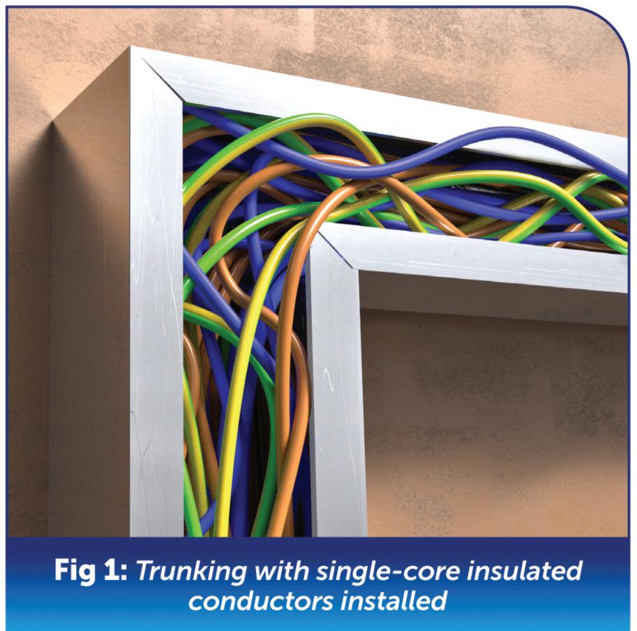
● Cables grouped in conduit and trunking systems
Appendix 4 of BS 7671 is basically the designers’ ‘go to’ guide for cable design as well as identifying the cross-sectional area of conductors
In this article, we will look at the requirements of BS 7671 as well as other guidance documents which designers can use to calculate the correct number of cables that can be installed in trunking and conduit systems
The capacities of conduit and trunking have not been included in BS 7671 since 1991, as the information was considered by the committee to be guidance However, BS 7671:2018+A3:2024 does provide relevant recommendations in Appendix 4.
This appendix discusses the current carrying capacities of conductors taking into account factors such as:
● Installation methods
● Rating factors
● Ambient temperature
Once we’ve established the type, size and number of circuit conductors to be installed, we now need to turn to further guidance to select an appropriately sized trunking or conduit
Fortunately, the IET On-Site Guide Appendix E contains more information regarding cable capacities for trunking and conduit
It is worth pointing out that this is guidance only and is concerned with the maximum number of cables that should be drawn in, so does not consider factors such as grouping as mentioned earlier in Appendix 4 of BS 7671 The use of this guidance should ensure that the cables can be drawn in easily and with the least risk of damage to them
The guidance deals with single-core thermoplastic (PVC) insulated cables in the following containment systems:
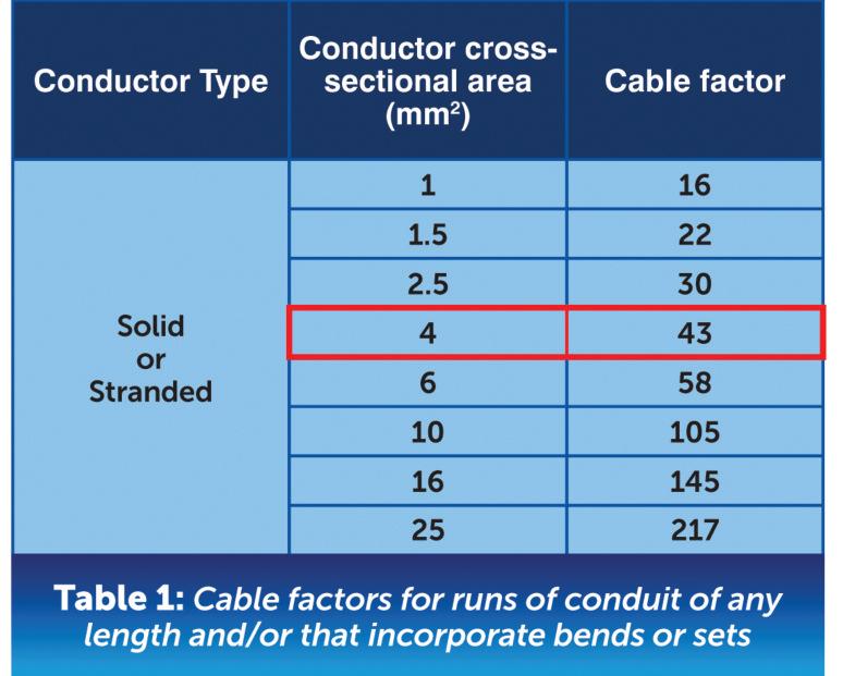
● Straight runs of conduit not exceeding 3 m in length
● Straight runs of conduit exceeding 3 m in length
● Runs of conduit of any length and/or that incorporate bends or sets
● Trunking
The IET On-Site Guide contains a set of tables (E1 to E6) that assist in the selection of conduit and trunking These tables provide allocated factors for conduit and trunking
Conduit worked example
Let’s assume we need to install two radial circuits within a metal conduit Each of the circuits are single phase, thermoplastic single-core cables with a 4 mm2 cross-sectional area
This means in total we have 6 x 4 mm2 conductors Let’s also assume that the conduit run is 5 metres in length and incorporates two bends How do we work out the required diameter of conduit?
Firstly, we look at Table 1 to work out the cable factor We can see that 4 mm2 conductors have a cable factor of 43 As
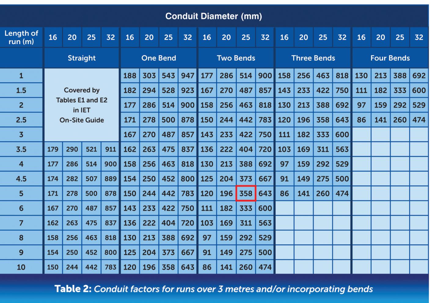
we have six conductors, we need to multiply the number of conductors by the cable factor
6 x 43 = 258
Therefore, our total cable factor for the two radial circuits is 258
Next, we need to look at Table 2 which will give us a conduit factor In our worked example, with a conduit 5 metres in length and incorporating two bends, we are looking for a factor that is greater than or equal to our total cable factor of 258
From Table 2, we can see a 5 metre run with two bends and there are only two choices of conduit diameter – 25 mm or 32 mm The conduit factor equal to or greater than our total cable factor of 258 is 358 This gives us a conduit diameter of 25 mm
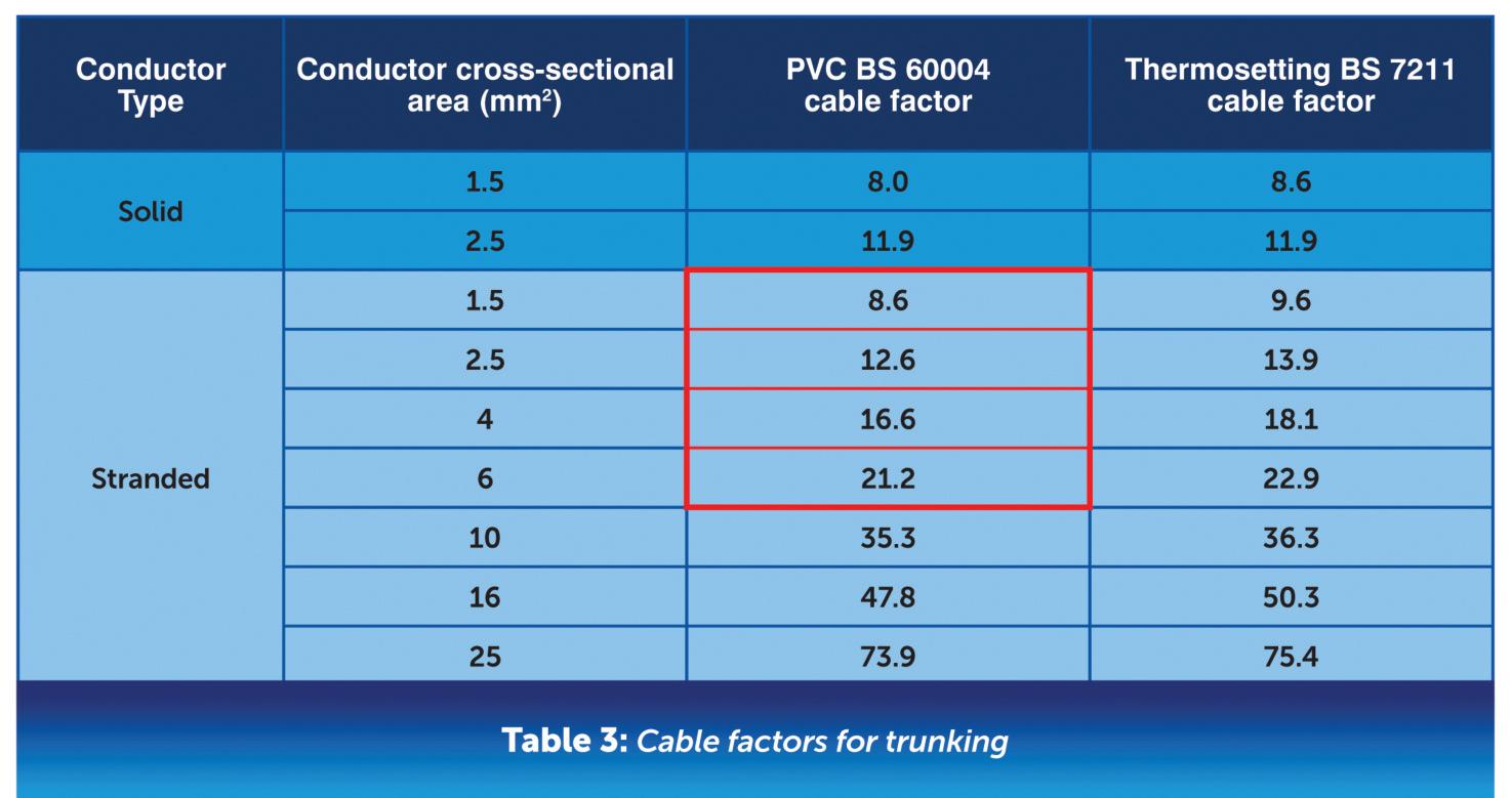
“The designer may choose to use a larger trunking depending on the specification, manufacturer and future use of the electrical installation.”
So we can see that a 25 mm conduit will ensure that our two radial circuits can be drawn in easily with a low risk of damage to the cables For cables and/or conduits not covered by these tables, the designer or installer should seek advice from the manufacturer on the number of cables that can be drawn in
Trunking worked example
Let’s assume we need to install the following single phase circuits that are wired with thermoplastic (PVC) single-core stranded cables within a trunking system:
● 4 x radial lighting circuits with a 1 5 mm2 cross-sectional area
● 4 x ring final circuits with a 2 5 mm2 cross-sectional area
● 2 x radial EV charge point circuits with a 6 0 mm2 cross-sectional area
● 3 x radial electric heater circuits with a 4.0 mm2 cross-sectional area
How do we work out the required size of the trunking?
Firstly, we look at Table 3 to work out the cable factors It is evident from the example that we are using four different conductor sizes, as well as multiple circuits.
We need to work out the cable factor for each conductor first:
● 1 5 mm2 cross-sectional area has a cable factor of 8 6
● 2 5 mm2 cross-sectional area has a cable factor of 12.6
● 4.0 mm2 cross-sectional area has a cable factor of 16 6
● 6 0 mm2 cross-sectional area has a cable factor of 21 2
Next, we need to multiply these cable factors by the number of conductors:
● 4 x radial lighting circuits with 12 conductors x 8 6 = 103.2
● 4 x ring final circuits with 24 conductors x 12 6 = 302.4
● 2 x radial electric vehicle charge point circuits with 6 conductors x 21.2 = 127 2
● 3 x radial electric heater circuits with 9 conductors x 16 6 = 149.4
To get the total cable factor, simply add these together:
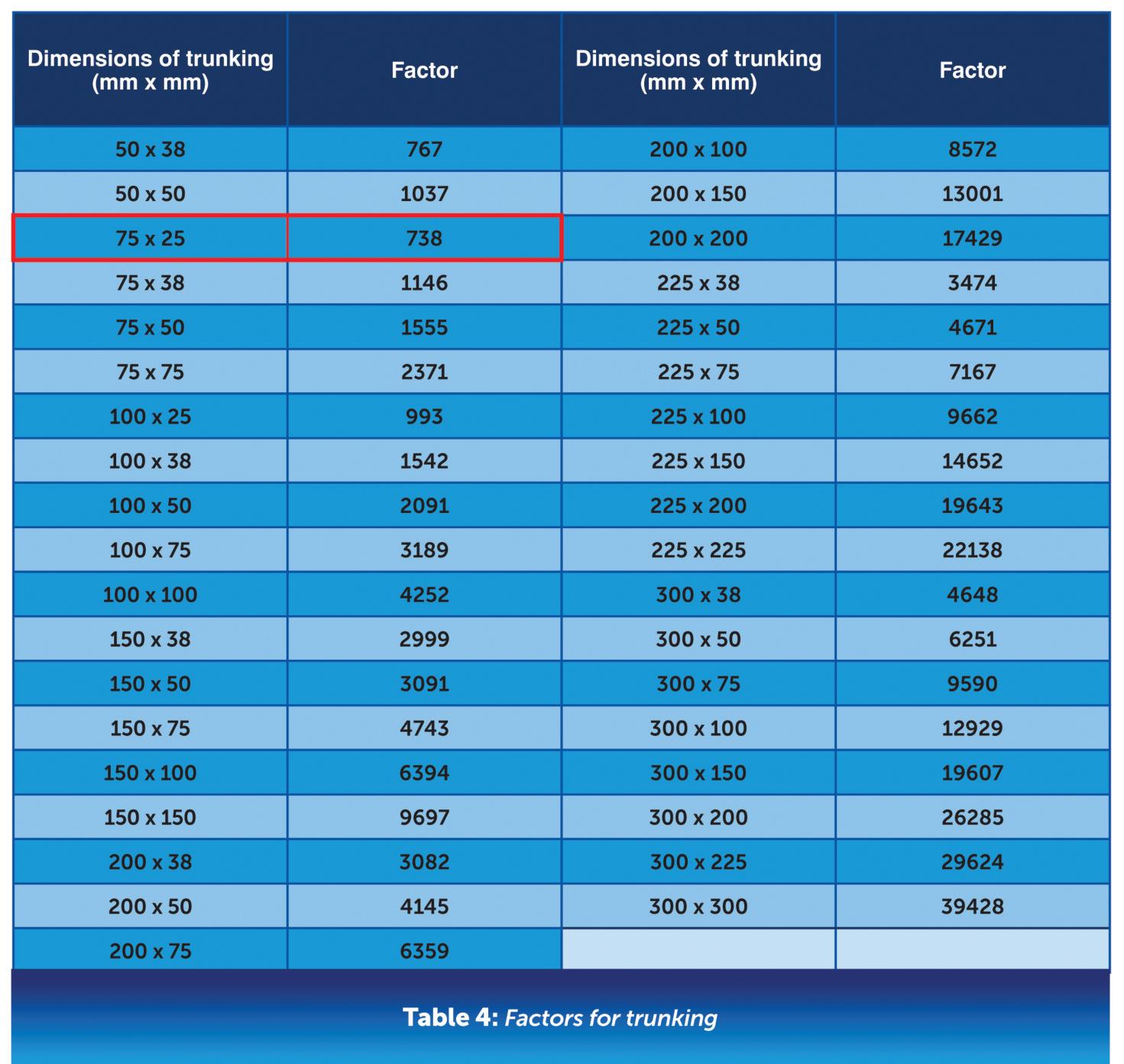
Now we turn to Table 4 to find a trunking factor that is greater than or equal to our total cable factor of 682 2 and this gives us a few choices
The trunking factor closest to our total cable factor of 682 2 is 738, which gives a trunking size of 75 mm x 25 mm
The designer may choose to use a larger trunking depending on the specification, manufacturer and future use of the electrical installation For cables and/or trunking not covered by these tables, the requirement is that a space factor of 45% must not be exceeded.
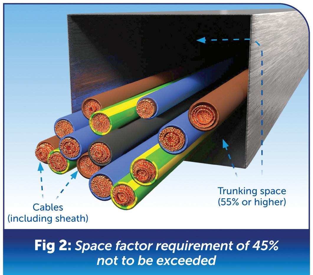
This means that not more than 45% of the space within the trunking must be occupied by cables, with 55% of free space, as shown in Fig 2.
Far too often we see containment systems, such as trunking and conduit, packed with cables way beyond their intended capacity
As mentioned earlier, this ultimately can lead to the potential danger of damaged cables during their installation or through overheating of conductors
Hopefully, this article has been useful in understanding the requirements of BS 7671 and other guidance documents for designers and installers to calculate the correct number of cables that can be installed in trunking and conduit systems.
“Far too often we see containment systems, such as trunking and conduit, packed with cables way beyond their intended capacity.”

As the installation of electrical energy storage systems and small-scale generation capable of feeding into the public distribution system becomes more widespread, it is increasingly common to have bidirectional power flow in some conductors within an installation
Batteries are considered to be generators for the purposes of BS 7671 (551 1 1(v)) and should also be considered as both a supply and a load (see note to regulation 823)
This raises issues in respect of the suitability, or otherwise, of protective devices such as circuit-breakers, residual current circuit-breakers (RCCB) and residual current operated circuit-breakers with integral overcurrent protection (RCBO).
Additionally, in such applications, consideration must also be given to which conductors must be disconnected when a protective device operates under fault conditions For example, it may be necessary to disconnect all live conductors so that a requisite disconnection time is achieved This is also discussed
Bidirectional protective device
A protective device where it is intended by the manufacturer that a source of supply is connected to either or both sets of connection terminals
Unidirectional protective device
A protective device where it is intended by the manufacturer that a source of supply is only connected to one defined set of connection terminals
Neither Section 551 nor Section 712 of BS 7671:2018+A2:2022, which give the general requirements for low voltage generating sets and the particular requirements for the installation of solar PV supply systems respectively, contain any specific requirements, or prohibitions, in respect of protective devices used in such applications other than requiring bidirectional overcurrent protective devices on the DC side of a solar PV system (712 431 101(d))

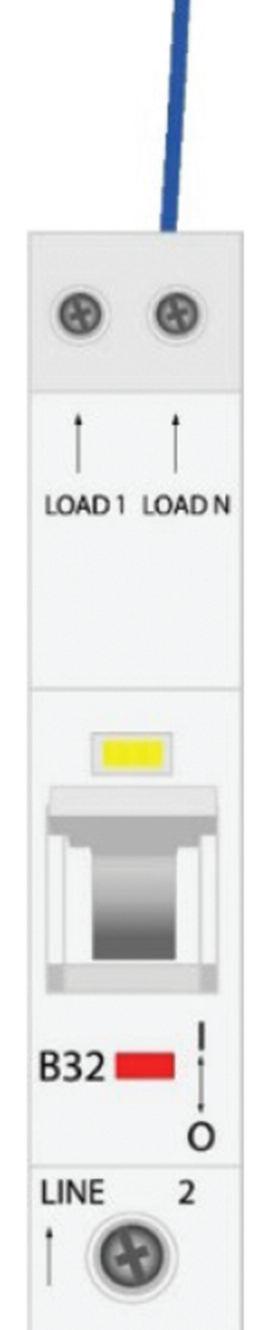
This article from the experts at NICEIC describes what factors must be taken into account when selecting protective devices for use in applications where bidirectional power flow is to be expected in normal operation. F ig 1 Typical means of identifying terminals of unidirectional RCBOs F ig 2 Typical means of identifying terminals of bidirectional RCBO
However, it is a requirement that overcurrent protective devices in prosumer’s electrical installations are suitable for all possible directions of current flow and polarity (826 1 2 2)
Suitability for use where bidirectional power flow is to be expected
Amendment 3 (AMD3) to BS 7671:2018, published in July 2024, introduced the following definitions:
AMD3 introduced a new regulation 530 3 201 in Chapter 53 (Protection, isolation, switching, control and monitoring) which states that the selection and erection of equipment for protection
shall take account of appropriate use of either a unidirectional protective device or a bidirectional protective device.
An accompanying note advises that the product standards for some protective devices such as RCCBs, RCBOs, circuit-breakers and AFDDs contain requirements for their marking to indicate if they are unidirectional
It further advises that this indication may be given by directional arrows, or by
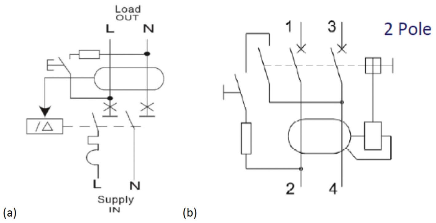
marking their terminals “in” and “out” or “line” and “load”
When working on such installations, where there is any doubt regarding suitability of a protective device for use in a particular application, the manufacturer’s instructions shall be taken into account (134 1 1; 510 3)
The BEAMA technical bulletin Connection of Unidirectional and Bidirectional Residual Current Devices (RCDs) and Miniature Circuit-Breakers (MCBs) to power supplies e g battery storage, Photovoltaic (PV) systems, Electric Vehicles (EV) to home, a micro-generator, or grid (mains) supply advises that, in some cases:
● connecting the output of the generator or battery to a protective device’s outgoing terminals, designated as ‘out’ or ‘load’ will result in damage rendering the device inoperable and
● circuit-breakers with terminals marked ‘in’ and ‘out’ or ‘line’ and ‘load’ may have their arc extinguishing and/or short-circuit operation characteristics impaired if they are connected incorrectly and the device operates under fault condition
Furthermore, in some cases, when a unidirectional residual current device is connected incorrectly, testing the device with a test instrument or even merely operating the ‘test’ button may also render the device inoperable
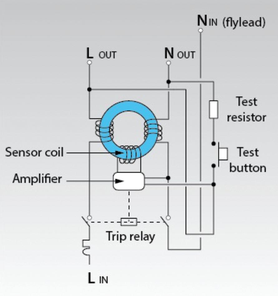
For both circuit-breakers and RCDs (RCCBs and RCBOs) it is unlikely that there will be any visually observable signs to indicate that damage has occurred Furthermore, even if the ‘test’ button can be reset this does not mean that the device is still capable of operating.
Product standards
Clause 6 1 (Standard marking) of BS EN 60898-1:2019 requires that:
If it is necessary to distinguish between the supply and the
load terminals, the former shall be indicated by arrows pointing towards the circuit-breaker and the latter by arrows pointing away from the circuit-breaker In the case of RCCBs and RCBOs, Clause 6 (Marking and other product information) of BS EN 61008 1:2012+A12:2017 and BS EN 61009-1:2012+A12:2016 both state:
If it is necessary to distinguish between the supply and the load terminals, they shall be clearly marked (e g by "line" and "load" placed near the corresponding terminals or by arrows indicating the direction of power flow)
An example of typically used arrangements is shown in Fig 1 Similarly, Fig 2 shows the terminal markings on a bidirectional RCBO
Clause 6 of both BS EN 61008 1:2012+A12:2017 and BS EN 61009-1:2012+A12:2016 also states that the devices covered shall be marked in accordance with the Table Z3 therein In both cases this states that, unless the correct mode of operation is evident and there is insufficient space in a visible position on the device, a wiring diagram should be included either:
● on the side or on the back of the device, visible only before the device is installed, or ● on the inside of any cover which has to be removed in order to connect the supply wires
Examples of such wiring diagrams are shown in Fig 3
Unidirectional RCBO failure mode
Fig 4 shows a circuit-diagram for a 1-ph and switched neutral unidirectional RCBO Unidirectional devices are designed for the supply to be connected to the incoming (supply) terminals (shown here as LIN and NIN) and the load to be connected to the outgoing (load) terminals (shown here as LOUT and NOUT) Where a solar PV system is connected to the outgoing terminals a voltage can remain present across the internal electronic components such as silicon control rectifiers (SCR) or thyristors in the signal amplifier circuit
or the trip-relay solenoid for up to 1 second1 after the device has operated In some designs of RCBO, this continued presence of voltage after the device has tripped can result in damage to such electronic components, which are typically short-time rated
One solution adopted by manufacturers to address this issue is to include a switching contact linked to the contacts in the line and neutral conductors, as shown in Fig 5. With this arrangement, when the device trips the supply to the amplifier and solenoid is also disconnected
Selecting protective devices for the AC side of a solar PV power supply system
Where the solar PV system forms part of a prosumer’s electrical installation (see Section 823), the overcurrent protective device must be suitable for bidirectional operation (826 1 2 2)
When a generating set, such as a solar PV system, is used as an additional source of supply in parallel with another source, where it is necessary to install an RCD to provide additional protection for an AC supply cable connecting a generator set to the installation, the RCD shall disconnect all live conductors, including the neutral conductor (551 7 1(ii))
This is necessary in order for the RCD to be able to operate within the requisite time to provide additional protection This necessity is discussed in detail in Best Practice Guide 3 –
Connecting a microgeneration system to a domestic or similar electrical installation (in parallel with the mains supply), published by Electrical Safety First It should be noted that BS 7671 does not recognise inverters of PV or battery storage systems as a means to provide additional protection.
According to BS EN 61009-1, an RCBO which disconnects all live conductors is classified as two-pole RCBO with one overcurrent protected pole, where the unprotected pole is a switched neutral, and the device has the following characteristics:
● overload/short-circuit protection in L, breaking both L and N as they are mechanically linked
● earth-leakage (RCD) protection breaking both L and N
● switching off the device breaks L and N, thus making it suitable to provide isolation of TN and TT system earthing arrangements
Many RCBOs do not switch the neutral and so would not be suitable for use to provide additional protection to the AC supply cable to the PV system
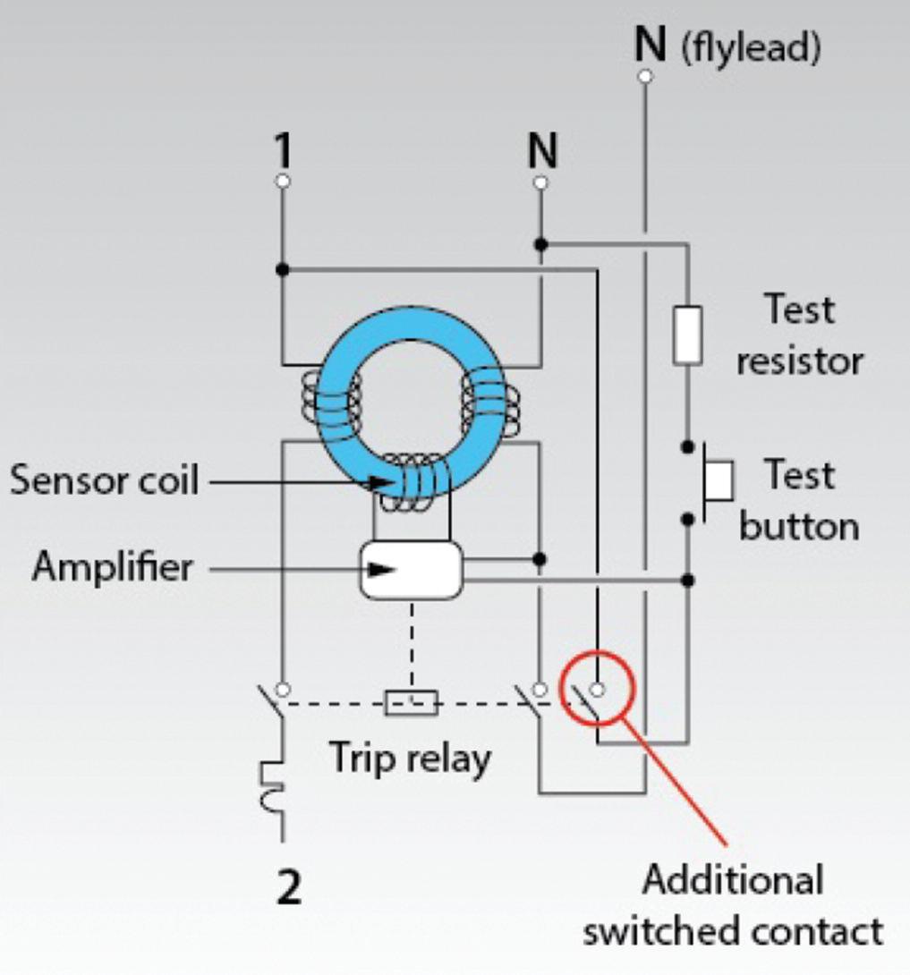
Unidirectional circuit-breakers and residual current devices (RCCBs and RCBOs) may suffer damage to the internal electronic circuitry sufficient to impair their functionality if the output of a generator or battery storage inverter is connected to their load terminals It is highly unlikely that this damage will be detectable during a visible inspection. Where bidirectional current flow is expected in normal use, such as where an installation includes small-scale generation or battery storage, suitable protective devices must be installed which take account of all possible directions of power flow and polarity.
Any RCD (RCCB or RCBO) installed to provide additional protection to the AC supply cable must be of a type which disconnects all live conductors Not all RCBOs switch the neutral Amendment 3 (AMD3) to BS 7671:2018 published in July 2024 introduced new definitions for both bidirectional and unidirectional protective devices and a new requirement that the selection and erection of equipment for protection shall take account of appropriate use of either a unidirectional protective device
or a bidirectional protective device
Where there is any doubt as to the suitability of a particular protective device for use in applications where bidirectional power flow is expected, the advice of the manufacturer(s) of the device(s) in question should be sought
1 Engineering Recommendation G98 Requirements for the connection of Fully Type Tested Micro-generators (up to and including 16 A per phase) in parallel with public Low Voltage Distribution Networks on or after 17 May 2019, published by the Energy Networks Association, advises that, for certain types of PV inverter, maximum shut down time on loss-of-mains may be up to 1 second

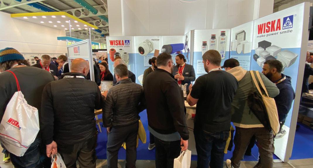


Taking place across two days at Sandown Park in Surrey, the last ELEX show of the year is just a few weeks away. What’s more, we’ve got great news for visitors that are serious about CPD!
Recent changes to The Electrotechnical Assessment
Specification (EAS) which sets out the minimum requirements for a business to be recognised as technically competent by a Certification or Registration Body, includes a requirement for businesses to maintain appropriate records of qualifications, training (including Continuing Professional Development) and experience.
To support this requirement, EVERY ELEX seminar is now CPD accredited, ensuring those individuals who make the time and effort to attend will receive a direct certificate of completion, which can

form a key part of your ongoing Continuing Professional Development record
With industry regulation and legislation changing constantly, the extensive ELEX seminar programme will cover an array of topics, including the latest Amendment 2 to the 18th Edition and the changes this covers, along with best practice and technical advice for professionals to get stuck into Presentations will be delivered by experts in their field and the only cost to delegates is their time
All seminars will take place in the IET Seminar Theatre located centrally in the exhibition hall and there’s no need for delegates to pre-book, just pre-register to attend the show
Whether you need some advice on the direction the sector is heading, want to chat with manufacturers about their latest solutions, view live demonstrations of the latest products or bag yourself a great
YOUR S H OW, NEA R YO U. . .
● At a venue near you
● Across two days
● Free parking (van friendly)
● Free entry
● Free T-Shirt & a free bacon roll* (*limited to first 1,000 visitors)
● Show bargains
● Hands-on demos
● Meet manufacturers
● Networking opportunities
● CPD accredited seminars and certificates
show deal on tools and equipment from leading brands, your regional ELEX tradeshow has it all
The final stop on this year’s ELEX 2025 tour takes place next month at Sandown Park in Surrey – 6th & 7th November, 10am - 4pm