TOOLING COMPONENTS AND MOULDING SUPPLIES

® Supplier s t o the Tooling & Plas tic Indus tr y
www.hales-asia.com.sg CONTENTS hot runner & control 73 alignment 2 mould actions 12 general 34 cooling products 51 EJECTOR PINS 43 MOULDING ACCESSORIES 64
HALES ASIA
STANDARD ISA TOLERANCES
Mould
MOULDING
Edition 4 V3 7-12-22 www.hales-asia.com.sg CONTENTS
Runner and control
73-75 Verishot 76 Multi Valve Gate 77 Mastip Manifold Systems 78-81
Pillars 2-5 Guide Bushes 6-8 Tapered Interlocks 9 Side Locks 10-11
Hot
Nozzles
Alignment Guide
12-13 Vacuumjet
Accelerator 17
Retainers
Devices
Units 30 Guide Bars 31 Ejector Couplers 32 Hydraulic Cylinders 33 General Date Stamps & Inserts 34-35 Air Poppets 36 Sintered Vents 37 Cycle Counters 38-39 Tunnel Gate Inserts 40 Limit Switches 41-42
Products
51-52 Flow Regulators 52
Monitor 53
Heat Transfer Rods
& Plugs
Ferrules
Pins Ejector Pins 43-46 Ejector Sleeves 47 Ejector Blades 48-49
Actions Cores
14-16 Plate
Slide
18-19 Slide Holding
19-22 Latch Locks 23-29 Slide
Cooling
Flowmeters
Flosense
Manifolds 54-55
56 Connectors
57-62 Hose, Hand Crimper,
63 Ejector
Table of Standard ISA Tolerances 70
Temperature Controllers 64-66 Connector Fittings & Plugs 67-68 Specialty Lubricants & Fluids 69-70 Nuts, Bolts, Washers and Clamps 71 Mould Curtain 72 Insulation Blankets 72
ACCESSORIES
TOOLING COMPONENTS & MOULDING SUPPLES CONTENTS

®
ALIGNMENT
Supplier s t o the Tooling & Plas tic Indus tr y


2 www.hales-asia.com.sg Alignment Edition 4 V3 7-12-22 Guide Pillars - W20 d2 k6 d2 e7 d2 e7 d3 -0,2 A ø0,01 K ±0,05 A Rz 2,5 L2 d1 g6 L4 A ø0,01 L3 L1 -0,05 -1 d1 L1 L2 d2 d3 K L3 L4 14/15 27 30 20 25 6 9 7 45
d1 L1 L2 d2 d3 K L3 L4 9/10 12 25 14 16 3 3 4 45
17
7
65 85 105 125 145 165 36 35 55 75 95 125 155 46 35 45 65 85 105 125 145 56 35 55 75 95 135 66 55 65 95 125 76 55 95 86 55 95 96 55 95 116 75
65
20 30 50 70 22 25 35 55 75 95 27 20 30 50 70 90 36 25 45 65 85 46 30 45 70 56 35 60 66 45 14/15 17 35 20 25 6 9
55 75 95 22 30 50 70 90 110 125 150 Mat. -Nr. 1.7131/60±2HRC Order: W20 - d1 - L1 - L2
Guide Pillars - W20
Order: STW20 - d1 - L1 - L2
d1 L1 L2 d2 d3 K L3 L4
18/20 17 35 26 31 6 9 7 55 75 120 22 35 45 65 85 115 27 35 45 65 85 105 125 165 225 245 36 35 55 75 95 115 135 165 225 225 46 35 45 65 85 105 135 165 245 56 35 55 75 95 155 66 35 55 75 95 145 76 55 75 95 135 86 55 75 95 125 96 55 95 116 75 115 136 135
d1 L1 L2 d2 d3 K L3 L4
22/24 17 35 30 35 6 9 7 55 75 22 35 55 75 105 130 27 35 45 65 85 105 125 165 205 245 285 36 35 55 75 95 115 135 165 205 245 285 46 35 45 65 85 105 125 165 205 56 35 55 75 95 115 165 205 66 35 55 75 95 155 76 55 75 95 115 145 86 55 75 95 135 96 55 75
3 Alignment Edition 4 V3 7-12-22
www.hales-asia.com.sg
125 116 75 115 155 136 95 135 156 155 30/32 27 45 42 47 6 9
65 105 165 185 245 285 36 55 75 95 115 155 245 285 46 45 65 85 105 125 165 245 285 56 55 75 95 115 135 175 245 295
30/32 66 55 42 47 6 9 7 75 95 115 135 175 245 295 76 55 75 95 115 155 225 86 55 75 95 115 155 225 96 55 75 95 115 155 205 116 75 115 155 136 95 115 155 156 115 155 196 155 195 40/42 46 95 54 60 10 12 7 165
4 www.hales-asia.com.sg Alignment Edition 4 V3 7-12-22 d1 L1 L2 d2 d3 K L3 L4
7
L1 L2 d2 d3 K L3 L4
22/24 96 95 30 35 6 9
7
d1
d1 L1 L2 d2 d3 K L3 L4
54 60 10 12 7
d1 L1 L2 d2 d3 K L3 L4
7
40/42 56 75
115 155 195 66 75 135 76 75 115 175 86 75 135 96 75 115 155
40/42 116 95 54 60 10 12
135 195 136 95 135 215 156 115 155 215 196 155 195 235 246 165 245
Guide Pillars - W20
Mat. -Nr. 1.7131/60±2HRC Order: W20 - d1 - L1 - L2

www.hales-asia.com.sg 5 Alignment Edition 4 V3 7-12-22 Guide Pillars - Z65
d3 0 -0 ,2 K L f 15 ° ±0,1 0 -0,5 d1 g6 R z 2, 5 Mat. -Nr. 1.7160/58±2HRC Order: Z65 - d1 - L d1 L d3 K f 10 60 12 6 3,5 80 90 12 60 16 6 3,5 80 90 100 120 140 14 60 18 8 4,0 80 100 120 140 160 180 16 60 20 8 4,0 80 100 120 140 160 180 18 60 22 8 4,0 80 100 120 140 160 180 d1 L d3 K f 20 80 24 8 5,0 100 120 140 160 180 200 220 24 100 28 15 5,0 120 140 160 180 200 220 240 280 28 100 32 15 5,0 120 140 160 180 200 220 240 280 32 160 36 15 6,0 200 250 300

6 www.hales-asia.com.sg Alignment Edition 4 V3 7-12-22 Guide Bushes -Z75 K d1
d1 +0 ,7 + 0 , 2 L3 d2 0 -0 ,2 L1 f7 d3 -0
-0
L2 +1 0 d2 k6 d 2 f7 A ø0,01
R z 6,3 R z
R z
d1 L1 L2 d2 d3 K L3
d1
L2 d2 d3 K L3
H7
,2
,7
A
4
2,5
9*/10* 16 L1 14 17 4 5 21 26 36 46 56 50 11/12 16 L1 18 22 4 5 21 26 36 46 56 51 66 15/16 16 L1 24 28 6 6 21 26 36 46 56 66 76 86 96 96 19/20 16 L1 28 32 6 8 21 26 36 46 56 66 76 86 96 96 25/26 21 L1 34 38 8 8 26 36
L1
25/26 46 L1 34 38 8 8 56 66 76 86 96 116 106 30/32 36 L1 42 46 8 8 46 56 66 76 86 96 116 136 120 156 150 176 150 38/40 46 L1 50 54 8 10 56 66 76 96 116 136 130 156 150 176 150 48/50 56 L1 63 70 10 10 66 76 96 116 136 156 150 176 150 Mat. -Nr. 1.2162/60±2HRC Mat. 17% Cr on Request * Without lubrication grooves Order: Z75 - d1 - L

www.hales-asia.com.sg 7 Alignment Edition 4 V3 7-12-22 Guide Bushes Self Lubricating - Z4077
L1 K d1 G7 L3 d2 0 -0, 2 L1 f7 d3 -0,2 -0,7 d2 k6 d2 f7 ø0 ,01 A A R 6, 3 z R 6, 3 z R 6, 3 z L2 +0, 7 +0,2 d1 +1 0 SN 1791d1/d2 -0,5 +0,3 Rz 25 Rz 6,3 d1 L1 d2 d3 K L2 L3 X1 11/12 16 18 22 4 >3 x d1 5 9,6 21 14,6 27
36
15/16 21 24 28 6 >3 x d1 6
26
36
46
56
21 28 32 6 >3 x d1 8
26
36
46
56
66
21 34 38 8 >3 x d1 8
26
36
46
56
66
76
Mat.: Bronze 190-220 HB S10/3000 Order: Z4077 - d1 -
20,6
29,6
12,4
17,4
27,4
37,4
47,4 19/20
12,0
17,0
27,0
37,0
47,0
57,0 25/26
9,5
14,5
24,5
34,5
44,5
54,5
64,5 96 84,5


Edition 4 V3 7-12-22 Alignment 8 www.hales-asia.com.sg Ball
alignment Antifrication Slideway Bushes - SN1777SR R z 1, 6 SN 1799 d1 K1 d2 f6 d L3 5 d2 h4 L2 S R z 6,3 -0,3 d3 SN 1792 d K1 L3 L2 d1 d2 d3 S SN 179212 30 25 14,0 17 24 29,5 1,2 24-1,4 41 16 45 30 15,0 22 28 34,4 1,5 28-1,2 54 70 45 20 45 35 19,5 26 35 41,4 1,5 35-1,5 54 70 50 25 45 35 23,0 31 40 47,5 1,75 40-1,75 58 d K1 L3 L2 d1 d2 d3 S SN 179225 70 45 23,0 31 40 47,5 1,75 40-1,75 78 95 50 32 68 55 25,0 40 50 58,4 2,0 50-2,0 80 95 40 63 55 25,0 48 60 68,6 2,0 60-2,0 73 90 112 75 32,0 Mat.: -Nr. 1.3505/63±2HRC+CuZn40 Order: SN1777SR - d - K1 R z 1, 6 SN 1799 d1 K1 d2 k6 d L3 d2 f6 L1 -0,3 d3 S R z 6, 3 d K1 L1 L3 d1 d2 d3 S 12 40 6 24 17 22 26 6 56 18 45 11 34 24 30 35 6 56 d K1 L1 L3 d1 d2 d3 S 30 56 21 54 38 46 52 6 75 95 Mat.: -Nr. 1.3505/63±2HRC Order: SN1776SR - d - K1
Guide Bush - SN1776SR

www.hales-asia.com.sg 9 Alignment Edition 4 V3 7-12-22 Tapered Interlocks
16
30 14 M5X10
40 19
50 24
12
29 M10X20 20
15
32
60 29 M10X20 20 14 15
Product Code D k6 T T1.T2 MXL A V L1 L2 HRC 55-60 Material SUJ2
Tapered Interlocks offer an easy solution to ensuring the alignment of die plates. Tapered Interlocks are made and sold in parts.
T -0.2 +0.4 1 1 D K6 3 L2 T2 3 Max. +0.2 +0.1 C1 D -0.1 -0.3 M 3 T1 V A˚ L2 R0.5 0.1 +0.2 -0.03 -0.01 C1 - 0.2 +0 D K6 1 TLP-16
+0.012
10 5 6 +0.001 TLP-20 20 +0.015
M6X12 13 8 9 +0.002 TPL-25 25 +0.015
M8X16 5° 16 11
+0.002 TLP-30 30 +0.015 60
14
+0.002 TLP-32
+0.018
+0.002
Hales

10 www.hales-asia.com.sg Alignment Edition 4 V3 7-12-22 Economy Side Locks D C L N L E G D A - 0.01 0 +0.005 0 -0.005 0 B K M M J f F HESL38 38 22 30 12 22 10.5 6.5 7 7 22 13 5 8 HESL50 50 21.5 30 17 21.5 10.5 6.5 11 11 34 16 5 8 HESL75 75 36 50 25 36 16.5 10.5 18 18 50 19 8 12 HESL100 100 45 65 35 45 16.5 10.5 22 22 70 19 10 12 HESL125 125 45 65 45 45 16.5 10.5 22 22 84 25 10 12 Product Code A B C D E F f G J K L M N HESL1.5 1.500 0.870 1.180 0.500 0.87 0.433 0.276 0.281 0.437 0.938 0.620 0.190 0.3 HESL2.0 2.000 0.870 1.180 0.680 0.87 0.433 0.276 0.375 0.437 1.250 0.620 0.190 0.3 HESL3.0 3.000 1.360 1.910 1.000 1.37 0.590 0.413 0.688 0.688
0.745
0.45 HESL4.0 4.000 1.870 2.640 1.375 1.87 0.590 0.413 0.875 0.875 2.750 0.745 0.500 0.45 HESL5.0 5.000 1.870 2.640 1.750 1.87 0.788 0.555 0.875 0.875
1.120 0.500 0.6 Product Code A B C D E F f G J K L M N
2.250
0.380
3.500

www.hales-asia.com.sg 11 Alignment Edition 4 V3 7-12-22 Titanium Coated Side Locks Male: YK30 54~56HRC Black Oxide Finish Female: SKD11(D2) 58~62HRC Titanium Nitride Coated R1 B H S1 S T S R2 R2 D2 D1 T R2 R2 A S S W 1/2 W C R1 Product W T A B C D1 D2 H R1 Pocket R2 S S1 SHCS Code 0 ±.001 ±.001 ±.001 ±.0003 0 Radius ±.010 ±.010 -.0005 0 -.0003 CSL37 1.0000 0.375 1.125 0.875 0.53 0.5000 0.4999 1.37 0.22 3/16 0.06 0.250 0.500 #10-32 x 1/2” CSL49 1.2500 0.490 1.125 0.875 0.66 0.5000 0.4999 1.50 0.22 3/16 0.06 0.250 0.750 #8-32 x 5/8” CSL50C 1.5000 0.500 0.875 0.875 0.56 0.5630 0.5629 1.40 0.22 3/16 0.06 0.250 1.000 #8-32 x 5/8” CSL50 2.0000 0.500 1.375 0.875 0.66 0.7500 0.7499 1.50 0.28 3/16 0.06 0.312 1.376 #10-32 x 5/8” CSL75 3.0000 0.750 1.875 0.750 1.13 1.2500 1.2499 1.96 0.53 1/4 0.12 0.375 2.250 1/4-20 x 3/4” CSL100 4.0000 1.000 2.375 1.375 1.25 1.5000 1.4999 2.59 0.53 1/2 0.12 0.500 3.000 3/8-16 x 1” CSL125 5.0000 1.250 2.875 1.375 1.63 2.0000 1.9999 2.96 0.53 1/2 0.12 0.625 3.750 1/2-13 x 1 1/4” CSL150 6.0000 1.500 2.875 1.375 1.75 2.5000 2.4999 3.09 0.53 1/2 0.12 0.625 4.750 1/2-13 x 1/2” Product T W A B C D H R S1 S2 SHCS Code +.00 +.00 +.00 +.00 .002/.005 +0.0 Pocket ±.25 ±.25 -.05 -.01 -.05 -.05 Clearance Per Side -0.1 Radius HCSLM50 16 50 21.5 21.5 12 17 43 5 8 11 M6-1.0x18 HCSLM75 19 75 36 36 17 25 72 5 12.5 18 M10-1.5x20 HCSLM100 19 100 45 45 23 35 90 5 15 22 M10-1.5x20 HCSLM125 25 125 45 45 23 35 90 5 20.5 22 M10-1.5x25 Material Standard
MOULD ACTIONS

®
Supplier s t o the Tooling & Plas tic Indus tr y
Mat.: 1.8159 Hardened 45 ± 3HRC Patented System
Minimum space required for installation, only needs the space of an ejector. No milling, grinding or hardening other than the machining of detail needed. All machining is made 90° to the parting line. No need for complex mechanical systems.
M4x16 (DIN7991) • PW.080825 8 8.2 25 11.5 4.5 4.5 140 18 21 2 M5x36 14 6 M5x16 (DIN7984) PW.081025 8 10.2 25 11.5 4.5 4.5 140 18 21 2 M5x36 14 6 M5x16 (DIN7984) PW.081030 8 10.2 30 11.2 4.5 12 4.5 175 20 26 2 M5x36 14 6 M5x16 (DIN7984) •
PW.081225 8 12.2 25 11.5 4.5 4.5 140 18 21 2 M5x36 14 6 M5x16 (DIN7984)

PW.081230 8 12.2 30 11.2 4.5 12 4.5 175 20 26 2 M5x36 14 6 M5x16 (DIN7984) •
PW.101430 10 14.2 30 13.6 5.5 16 5.5 175 20 26 2.5 M6x36 18 8 M6x16 (DIN7984) •
PW.101630 10 16.2 30 13.6 5.5 16 5.5 175 20 26 2.5 M6x36 18 8 M6x16 (DIN7984) •
PW.101830 10 18.2 30 13.6 5.5 16 5.5 175 20 26 2.5 M6x36 18 8 M6x16 (DIN7984) •
12 www.hales-asia.com.sg Mould actions Edition 4 V3 7-12-22 Sprung Core
Product Code A B C D E G K L M N R T U V W CS
6 6.2 22 9 3.5 3.5 125 16 18 1.25
12 5
6 6.2 30 10 3.5 12 4.5 175 20 26 1.25
12 5
•
6 8.2 22 9 3.5 3.5 125 16 18 1.25
12 5
6 8.2 30 10 3.5 12 4.5 175
26 1.25
5
6.3 K C L 0.5 0.5 90˚ E D 6˚ +2 +0.1 ±0.2 6.3 ±1 øA øU øA 0.5 R V 0.1 Min.2˚ Min.C +0.5 +0.2 +0.1 +0.1 Max.C Min. 1 Max M Max N 6.3 6.3 B 15xøG øAg6 T 4 Hard. 58 ± 2 HRC. W +0.1 Mat. Bronze 6.3 IMPORTANT
PW.060622
M4x36
M4x16 (DIN7991) PW.060630
M4x36
M4x16 (DIN7991)
PW.060822
M4x36
M4x16 (DIN7991) PW.060830
20
M4x36 12

www.hales-asia.com.sg 13 Mould actions Edition 4 V3 7-12-22 Flexible Core Max.12 Max.16 Min.1 IMPORTANT 6.3 6.3 6.3 2.5 4 30 6.3 200 ±2 øB 8 R 0.15 -0.05 -0.2 A -0.02 øH +0.5 Min.36 IMPORTANT R 0.1 0.1 5˚ 4H7 x AH7 Product Code A B H Balinit C ® Hardness PF.064200 6 12 7 u 52 ± 2 HRC. PF.0642WB 6 12 7 - 58 ± 2 HRC. PF.084200 8 14 9 u 52 ± 2 HRC. PF.0842WB 8 14 9 - 58 ± 2 HRC. PF.104200 10 16 11 u 52 ± 2 HRC. PF.1042WB 10 16 11 - 58 ± 2 HRC. PF.124200 12 18 13 u 52 ± 2 HRC. PF.1242WB 12 18 13 - 58 ± 2 HRC. Minimum space required for installation, only needs the space of an ejector. No milling, grinding or hardening other than the machining of detail needed. All drilling is 90° to the parting line. Available with and without Balinit C® coating. Mat.: 1.2101 Hardened 45 ± 3HRC Patented System

14 www.hales-asia.com.sg Mould actions Edition 4 V3 7-12-22 Vacuumjet Unit 16 17 M4x25 DIN7991 52 96 ø16 36 16 ø10 ø6 8 18 2+0.5 R5 14 22 Silencer 17 ø8 ø10 H8 5 19 M4x10 6±0.2 18 16 Min.110 24 R6 Product Code A B C D E H VJ.600000 Vacuumjet 60L 5-6 Bar -900 mbar 75nl./Min. 60nl./Min. W.161416 Material: Aluminium Maximum working temperature: 80°C Patented System
Several units can be connected together in the same vacuum circuit.

www.hales-asia.com.sg 15 Mould actions Edition 4 V3 7-12-22 Vacuumjet +
Product Code Type VG523016 60L
Aluminium
Material:
Maximum working temperature: 80°C Patented System

Edition 4 V3 7-12-22 16 www.hales-asia.com.sg Mould actions Vacuumjet Valves ø3 ø4 L±1 øA H7 M 8 D+0.05 øC -0.2 øA m6 øAg6 ø3 D -0.05 4 ≥ 0.2 Max. 2.5 øB-0.2 Product Code A B C D VV.086414 8 6.7 7.5 14 VV.121014 12 9.8 10 14 VV.161416 16 14 10 16 ø3 ø4 L±1 øA H7 M 8 D+0.05 øC -0.2 øA m6 øAg6 ø3 D -0.05 4 ≥ 0.2 Max. 2.5 øB-0.2 ø3 ø4 L±1 øA H7 M 8 D+0.05 øC -0.2 øA m6 øAg6 ø3 D -0.05 4 ≥ 0.2 Max. 2.5 øB-0.2 Product Code L M VT.043134 134 150 VT.043209 209 225 VT.043284 284 300 Product Code A B C mm JV.030200 3 2.7 2.7 2.000 JV.050200 5 4.6 4.2 2.000 øA Ensure join is sealed using silicon C B R0.25 R0.8 25° øA øA Ensure join is sealed using silicon C B R0.25 Mould actions Vacuumjet Valve Tubes Mould actions Vacuumjet Valve Seals

www.hales-asia.com.sg 17 Mould actions Edition 4 V3 7-12-22 Plate Accelerator Hard 58± 2 HRC. Mat.
øB E G F M D A L max. H max P DIN 6325 T DIN 912 Max. N
6.3 6.3 6.3 4 Product Code B C D E F G H max. L max. M N P T Max. Force EP.200813 20 8 13.2 25.8 9.4 11.4 6 13.6 5.5 5 15 Ø2.5x10 M3x12 75kg EP.251016 25 10 16 32.3 11.8 14.3 7 17 6.8 6 18.5 Ø3x12 M4x16 125Kg EP.371522 37.5 15 22 48.5 17.7 21.5 10.5 25.5 10.2 8 25 Ø4x16 M6x25 250Kg EP.502030 50 20 30 64.6 23.6 28.6 14 34 13.6 10 34 Ø5x20 M8x30 500Kg Simple
Offers
1.0503
C±0.2
mechanical double ejection system. Minimum space required for installation. Avoids complex systems like others currently available in the market.
a standard solution to the moulder.

Edition 4 V3 7-12-22 18 www.hales-asia.com.sg Mould actions C DIN7979 B ER F T DIN7791 0.5 A Hard. 58±2 HRC K K = Force to release the RC L M DIN7991 ØPg6 ØCH7 Mechanical stop recommended Mechanical stop recommended G min. A+0.1 G min. A+0.1 1 1 2 H F +0.5 N+0.5 2 F +0.5 ØPH7
K = Approximate resistance value that can be obtained by grouping clips Ø8 DIN6325 K Hard. 58 ± 2 HRC 65 60 16 16 8
2.5
3 K*1 RM = 7.5kg K*2 RM = 15kg K*3
K*4
Closed Mould 1st Opening 2nd Opening Product Code K RM.651608 7.5kg No pocket machining required as needed with other similar products on the market. Minimum space required for installation. Reduces costs compared to conventional mechanisms. Offers a standard solution to the moulder. Mat.: 1.8159 Hardened 45 ± 3HRC Patented System
K = Approximate resistance value that can be obtained by grouping clips Ø8 DIN6325 K Hard. 58 ± 2 HRC 65 60 16 16 8
2.5
3 K*1 RM = 7.5kg K*2
15kg
30kg Closed Mould 1st Opening 2nd Opening Modular Retainer
IMPORTANT
Ø8 DIN6325
M8 DIN912
RM = 22.5kg
RM = 30kg
IMPORTANT
Ø8 DIN6325
M8 DIN912
RM =
K*3 RM = 22.5kg K*4 RM =


www.hales-asia.com.sg 19 Mould actions Mould actions Edition 4 V3 7-12-22 Slide Retainer C DIN7979 B ER F T DIN7791 0.5 A Hard. 58±2 HRC K K = Force to release the RC L M DIN7991 ØPg6 ØCH7 Mechanical stop recommended Mechanical stop recommended G min. A+0.1 G min. A+0.1 1 1 2 H F +0.5 N+0.5 2 F +0.5 ØPH7 Product Code A B C E F G H K R T RC.123006 12 30 6x20 21 5 4 16 5 Kg 6 M5x16 RC.164008 16 40 8x20 28 6 5 15 7 Kg 8 M6x25 RC.205010 20 50 10x24 34 8 6 17 14 Kg 10 M8x30 RC.246012 24 60 12x32 42 10 7 23 21 Kg 12 M10x40 RC.328012 32 80 16x40 56 12 9 27 28 Kg 16 M12x50 RC.328016 32 80 16x40 56 16 9 25 38 Kg 16 M12x50 Less machining for installation compared to similar products on the market. Minimum space required for installation. Reduces costs in tool downtime. Offers a standard solution to the moulder. Slide Retainers Mat.: 1.8159 Hardened 45 ± 3HRC Patented System Slide Holding Devices - Z5129 t4 B1 ±0 ,05 P1 P2 D3 t1 -0,0 5 t3 D4 SN 3550 SN 2500 90° R t2 D2 D1 B2 ±0 ,05 g6 H7 g6 B3 ±0 ,1 HT "HT" ^ = Z 5129 max. 250°C Mat. -Nr. 1.2842/58 + 2HRC Order: Z5129 - D1 D1 B1 B2 B3 t1 t2 t3 t4 D2 D3 D4 R P1(N) P2(N) SN 2500 SN3550 13 6,6 1,4 4,3 10 1,0 1,6 0,35 7 2,2 M3 0,35 28 34 5-12 M2-16 18 9,6 2,0 6,0 14 1,8 2,0 0,50 10 3,2 M4 0,5 38 42 8-16,5 M3-20 27 14,4 3,0 9,0 21 2,8 3,0 0,50 15 4,3 M5 0,75 38 92 11,6-18,5 M4-25


Edition 4 V3 7-12-22 Mould actions 20 www.hales-asia.com.sg Slide Holding Devices - Z5140
Type 0 1 2 Max. 100 C Max. 100 C Max. 100 C SN 3500-4-16 SN 2500-6-15 P2 =70N P1 =62N 14 -0,01 -0,03 R0,5 90° 12 -0,0 5 -0 ,1 2 1, 8 28 38 -0,0 5 R6 16, 5 -0 ,2 M5 Ø4 , 2 4,5 Ø8 0 18 -0,03 R0,5 90° 14 -0,0 5 -0 ,1 2 P2 =126N P1=114N R8 43 53 -0,0 5 1, 8 M5 Ø4 ,2 SN 3500-4-16 Ø8 4,5 32 -0 , 2 SN 2500-8-16,5 SN 2500-8-16,5 P2 = 252N P1 = 228N M5 Ø 4, R0,5 90° 2 16 -0,0 5 -0 1, 4, 5 0,2 44 48 -0,01 -0,03 36 5 6 5 0 , 0 - 44 R8 0

www.hales-asia.com.sg 21 Mould actions Mould actions Edition 4 V3 7-12-22 Slide Holding Devices - Z5134 Slide Holding Devices - Z5130 D1 B1 B2 B3 t1 t2 t3 t4 D2 D3 D4 R P1(N) P2(N) SN 2500 SN3550 13 6,6 1,4 4,3 10 1,0 1,6 0,35 7 2,2 M3 0,35 28 34 5-12 M2-16 18 9,6 2,0 6,0 14 1,8 2,0 0,50 10 3,2 M4 0,5 38 42 8-16,5 M3-20 27 14,4 3,0 9,0 21 2,8 3,0 0,50 15 4,3 M5 0,75 38 92 11,6-18,5 M4-25 Mat. -Nr. 1.2842/58 + 2HRC Order: Z5130 - D1 t2 t1-0,05 t3-0,05 D2 g6 R D1 D3 L0 Ln t4±0,05 P2 SN 2500 B1±0,05 D2-0,0 5 max. 100°C D2 B1 t1 t2 t3 t4 D1 D3 R L0 Ln P2(N) SN25007 6,6 7 1,0 1,4 6,3 8,4 5,3 0,35 12 7,5 34 5-12 10 9,6 10 1,8 2,0 9,0 12,0 8,3 0,50 16 10,0 42 8-16,5 15 14,4 15 2,8 3,0 13,5 18,0 12,4 0,75 18 16,0 92 11,6-18,5 Mat. -Nr 1.2842/58 ± 2HRC Order: Z5134 - D1 t4 B1 ±0 ,05 P1 P2 D3 t1 -0,0 5 t3 D4 SN 3550 SN 2500 90° R t2 D2 D1 B2 ±0 ,05 g6 H7 g6 B3 ±0 ,1 HT "HT" ^ Z 5129 max. 250°C 5130 100

22 www.hales-asia.com.sg Mould actions Edition 4 V3 7-12-22 Slide Holding Devices - Z5130 Z5134
Z
1: Z 5134 2: Z 5134 3: Z 5130 Z 4242
5134

www.hales-asia.com.sg 23 Mould actions Edition 4 V3 7-12-22 Round Latch Locks - Z3-3 . . . Z3-31 L4 M1 2 L1±0,1 SW ø30 g6 18,4 +0,1 ø42 k6 ø9 H13 ø15 H13 6 L3 M12 18 R9 57 S1max. 12 42 Pos. 06 L2 +0,1 only
L3 M8 M1 2 ø42 k6 18 R9 57 S1max.
42
S1 max. L1 L2 L3 L4 125 50 175 130 76 225 75 175 155 101 50 225 100 175 180 126 225 S1 max. L1 L2 L3 L4 125 275 205 151 325 150 275 230 176 325 50 175 275 255 201 325 Z3 - 3Z3 - 31Pos. 09 Pos. 10 Pos. S D 11 5 30 10 Pos. S D 12 5 42 10 Z3 - 3 - Z3 - 3Z3 - 342 ø46 ø30 H7 8 -0,05 35 -0,05 Mat. -Nr.1.7139 ~58HRC ø42 k6 ø13 Guide Bush 13 Allowance for correction ø46 -0,2 ø2 0 H1 3 8,5* 20 -0,1 +0,2 Mat. -Nr.1.7139 ~600 N/mm² Mat. -Nr.1.7139 ~600 N/mm² ø1 3 H1 3 ø4 2 -0,4 -0,2 Counter Bearing S +0,5 ø13 D -1 -0,5 Distance Washers Guide Bush Counter Bearing Distance Washers
at S1max. 125/150/175 only at S1max. 125/150/175 STZ 3-3 STZ 3-31
12
Pos.061 L2 +0,1
24 www.hales-asia.com.sg Mould actions Edition 4 V3 7-12-22
Z3-31
Type Item L1 L2 Description Quant. Mat.-No Hardness 3 01 125 -
1
31 01 175 -
01 225 -
01 275 -
01 325 -
3 02 - 130
31 02 - 155
02 - 180
02
02
3
3
-
31
Round Latch Locks - Z3-3 . . .
Installation independent of guide system Installation in the guide system bores 11 12 53 48 76 10 Z81 91 25 34 87 610 Z 3-3 Z 3-31
Latch Bar
1.5920 58 HRC
Latch Bar 1 1.5920 58 HRC
Latch Bar 1 1.5920 58 HRC
Latch Bar 1 1.5920 58 HRC
Latch Bar 1 1.5920 58 HRC
Housing 1 1.5920 54 HRC
Housing 1 1.5920 54 HRC
Housing 1 1.5920 54 HRC
- 205 Housing 1 1.5920 54 HRC
- 230 Housing 1 1.5920 54 HRC 02 - 255 Housing 1 1.5920 54 HRC 3 03 - - Piston 1 1.2343 52 HRC 31 04 - - Securing Ring 1 1.2379 56 HRC 05 - - Catches 2 1.2379 56 HRC
06 - - Driver 1 1.2343 52 HRC 31 061 - - Driver 1 1.2343 52 HRC
07 -
Socket set screw M6x8 1 Din 915
08 - - Spring 1 1.7103 Z3Installation independent of guide system Installation in the guide system bores
Latch
Mould actions


Latch Locks - Z4-17


www.hales-asia.com.sg 25 Mould actions Edition 4 V3 7-12-22
Two Stage Ejector
Locks - Z4-15
Latch Casing - top tie beam and tension strip pinned Type L Type L 0-0 0 50-0 50 25-0 25 75-0 75
Extended Steady Type L Type L 0-41 0 50-41 50 25-41 25 75-41 75 Type 0-0
Type L Type L
0-0 0 50-0 50 25-0 25 75-0 75


26 www.hales-asia.com.sg Mould actions Edition 4 V3 7-12-22 Latch Locks - Z4-16 Two Stage Ejector Latch Casing - top tie beam and tension strip pinned Extended Steady Type L Type L 0-0 0 50-0 50 25-0 25 75-0 75 Type L Type L 0-41 0 50-41 50 25-41 25 75-41 75 Type 0-0
Latch Locks - Z5-0, Z5-1, Z5-2

LATCH LOCK Z5-0


LATCH LOCK Z5-1

LATCH LOCK Z5-2

www.hales-asia.com.sg 27 Mould actions Edition 4 V3 7-12-22
Latch Locks
Designed for simplicity and positive plate pulling, the three plate latch system is easily installed.

Mounted externally, the latch and cam plate assembly provides for easy adjustment of plate stroke and positive plate stop positions. The LS01 and LS02 cam plates are easily adjusted by socket head cap screw, while still in the machine.
Since the latch and the cam plate are separately attached to the mould, there is no possibility of overstroking the machine and causing mould damage.
Available in a range of sizes.
3 Plate Application
Product Code A B d
ZH 90/1 3 30 M10
ZH 90/2-3-4 14.5 30 M10

ZH 91 14.5 40 M12
4 Plate Application

28 www.hales-asia.com.sg
Edition 4 V3 7-12-22
Mould actions
ZH90/...-ZH91


www.hales-asia.com.sg 29 Mould actions Edition 4 V3 7-12-22 Product Code L3 max. L2 L1 L Type ZH 90/1 60 110 120 140 A ZH 90/2 124 170 184 204 A ZH 90/02SP 124 224 234 254 A Product Code Type L ZH 90/03 F 200 ZH 90/04 F 250 ZH 90/05 F 300 Product Code L1 L Type ZH 90/02SP 90 172 P ZH 90/2 170 252 P ZH 90/3 220 302 P ZH 90/4 270 352 P Product Code Type ZH 90/01 S Latch Locks ZH90/...-ZH91 Latch ZH 90/.. Latch & Cam Plate ZH 91 ZH
5,7 M6 20˚ 8 3 0,5 H h2 0 -0,05 6
S øD/2 d2 t1 t2 6,5
4
h1 H h2 0 -0,05
øD k6 5
L±0,1 L2 B -0,005 -0,010 L1 L3 1
4 t3±0,0 5 d1 Z 3158-5 (Type 0 = 1x) Type 0
M8 20˚ øD/2 S d2 0,5
t2 t1 8 t3±0,05 d1
4 Mat.: -Nr. 1.2342/52 HRC
Z 3158-5 (Type 1 = 1x) Z 3158-5 (Type 2 = 2x)

L L2 B +0,0 2 -0,01 L1 L3 2 40 22 6,4 60,5 20,0 40,0 28 8,0 12,0 50,0 8,0
ød 17
t2 t1 8 t3±0,05 d1 Z 3158-5 (Type 1 = 1x) Z 3158-5 (Type 2 = 2x) Type 1Type 1 1 25 11 3,4 61,5 26,5 34,5 18 2,5 16,5 32,8 10,8 13,9 24,2 3

øD k6 37,0 4
L1 L2
20,0
M6 M4
h1 H h2 0 -0,05 L3 d d1 d2 0 16 10 2,7 44,0 15,0 28,5 16 6,0 12,5 36,0 12,0 16,0 25,0 3
M6 M3
M8 M5
Edition 4 V3 7-12-22 Mould actions 30 www.hales-asia.com.sg Slide Unit - Z4290
ød
Type 1Type 1
L L2 B +0,0 2 -0,01 L1 L3
øD k6
4
ød 17
M8 20˚ øD/2 S d2 0,5 Type D B S H h1 h2 t1 t2 t3 L

www.hales-asia.com.sg 31 Mould actions Edition 4 V3 7-12-22 Square Guide Bar - Z46 B1 L1 L2 A B2 D1 D2 a1 b1 t1 t2 R 16 20 20 22 45 6,8 M8 11 30 11,5 12 8 20 40 22 45 6,8 M8 11 30 11,5 12 8 30 26 40 35 60 6,8
46
10 26 63 35 60 6,8
48 36 32 46 100 10,3
36 50 46 100
36 63 46 100
36 80 46 100
77 56 50 60 150 14
56 71 60 150 14
56 100 60 150 14
M8 17,5
19,5 20
M8 17,5 46 19,5 20 10
M12 23 74 25,5 26 12,5
10,3 M12 23 74 25,5 26 12,5
10,3 M12 23 74 25,5 26 12,5
10,3 M12 23 74 25,5 26 12,5
M16 30 114 35,5 36 16
M16 30 114 35,5 36 16
M16 30 114 35,5 36 16 t2 R B1 +0,007 +0,002 B2 +0,005 A ±0,1 a1±0,1 b1 ±0,1 ~ 50 HRC D2 D1 L1-0,1 DLC Coating on Request ~ 52 HRC B1 -0,00 5 L2±0,1 L1-0,1 D1 D2 R t1 B2 -0,005 a1±0,1 A±0,1 A B1 0,00 5 A

32 www.hales-asia.com.sg Mould actions Edition 4 V3 7-12-22 Ejector Couplers Mould Closed Material Injected Mould Open-Coupler Engages & Pushes Forward Coupler and Bars Pull Back the Ejector Plate L M K D E C F G HI J Product Code Thread F G H I J K L M 302M12COUP 12x1.75 34 32 32 39 43 9 15 42.5 402M16COUP 16x1.5 40 38 38 48 53 13 15 52 402M162COUP 16x2 40 38 38 48 53 13 15 52 402M20COUP 20x1.5 40 38 38 48 53 13 15 52 412M16COUP 16x1.5 58 56 52 65 70 17 18 68 Coupler Product Code Thread C D E 301M12BARB 12x1.75 22.8 20 45.5 401M16BARB 16x2 25.8 20 55 401M20BARB 20x2.5 25.8 20 55 411M16BARB 16x2 35 35 68 Barbs
V250CE Compact Block Hydraulic Cylinder
The V250CE cylinders have been specially designed for being extremely compact and for applying the integrated end stroke magnetic switches. Furthermore their construction permits a high standardization with consequent lower price and immediate delivery time. Available bores: from 25 to 100 mm. Strokes 20, 50 and 80 mm. Depending on the bore. These cylinders are ideal for short stroke slides and cores on plastic injection moulds. The use for heavy duties is not recommended.

Technical Features: Max. working pressure: up to 250 bar (3625 PSI)


Bore Size: 25 to 100 mm
Rod Size: 18 to 45 mm
Max. working temperature : Magnetic version: 80°C - 176°F
Non-Magnetic version: 100°C - 212°F Stroke : 20, 50 and 80 mm (according to the bore size)
V215CR Tie Rod Hydraulic Cylinder
The cylinders of V215CR range are built according to ISO 6020/2 Compact Norms and they are changeable with other similar cylinders (with reserve; personally verify all dimensions). This model permits a wide range of applications with the best compromise between quality and price where not particular requirements about pressure, temperature, dimensions are requested. Till bore 160 magnetic switches can be applied (with a proper version).
Technical Features: Max. working pressure: up to 215 bar (3117 PSI)
Bore Size: 25 to 200 mm
Rod Size: 12 to 140 mm
Max. working temperature : Magnetic version: 80°C - 176°F
Non-Magnetic version: 120°C - 248°F Stroke: 20 and 1500 mm (according to the bore size)
V260CF Self-Locking Rod Hydraulic Cylinder
The V260CF are double-acting hydraulic cylinders with a mechanical locking system of the rod in the end stroke position (extended rod), which permits to contrast very high opposite thrusts. Such a solution is widely applicable in the field of plastic injection and die-casting moulds, in order to stand the injection pressure on large moulding surfaces. The rod is hydraulically unlocked automatically when the piston comes back. WARNING: For a correct functioning the cylinder it’s necessary to complete all the times the total available cylinder stroke, both forward and backward, in order to assuring the locking on one side and to avoid hammer-effects on piston-rod screw on the other side. For a firm locking it is necessary to keep the oil in pressure, when pushing, at a minimum of 120 bar-1740 PSI.- Pay great attention to the traction force, which is considerably lower than the thrust.
Technical Features:
Max. working pressure: up to 260 bar (3770 PSI)
Bore Size: 30 to 84 mm
Rod Size: 20 to 60 mm Stroke: 30 and 150 mm (according to the bore size)
Max. working temperature : Magnetic version: 80°C - 176°F
Non-Magnetic version: 160°C - 320°F Head to the Vega website for more options
www.hales-asia.com.sg 33 Mould actions Edition 4 V3 7-12-22
Hydraulic Cylinders

®
Supplier s t o the Tooling & Plas tic Indus tr y
GENERAL
CFA.0422SF FA.042212-... FA.042204-... FA.042200 4 2.2 6 3.5 12 4
CFA.0530SF FA.053012-... FA.053004-... FA.053000 5 3 6 3.5 12 4
CFA.0632SF FA.063212-... FA.063205-... FA.063200 6 3.2 12 4 20 5
CFA.0847SF FA.084712-... FA.084705-... FA.084700 8 4.7 12 6 20 5

CFA.1057SF FA.105712-... FA.105706-... FA.105700 10 5.7 12 8 20 6 CFA.1267SF FA.126712-... FA.126708-... FA.126700 12 6.7 12 10 20 8
CFA.1687SF FA.168712-... FA.168710-... FA.168700 16 8.7 12 12 20 10
General
CFA.2007SF FA.200712-... FA.200710-... FA.200700 20 10.7 12 14 20 10 When replacing the insert, be sure to tighten until hearing the engagement “click”.

Edition 4 V3 7-12-22 34 www.hales-asia.com.sg General
Date Stamps
A
Date Insert 12 Months 12 Month + Year Year Blank
C D E L N
ØC
L+0.1 M 1 2 1 2 3 L -0.05 ØA g6 ØA m6 ØC D+1 4 12 Months Year N Blank CAD Insertion Point 12 Months + Year 4 6.3 //
A A Arrow Only Year + Arrow ØAH7 Bronze ØE 09 13 15 11 16 12 14 10 12
3
21 7
1110 4
12
0
When
the insert,
to tighten until
IMPORTANT ØC -0.03 L+0.1 M 1 2 1 2 3 12 Months Year N Blank CAD Insertion Point 12 Months + Year 4 A Arrow Only Year + Arrow ØAH7 Bronze ØE 09 13 15 11 16 12 14 10 12 6 3 9 21 7 8 1110 4 5 12 6 3 9 21 7 8 1110 4 5 0 0 When replacing the insert, be sure to tighten until hearing the engagement “click”. IMPORTANT ØC -0.03 L+0.1 M 1 2 L -0.05 ØA g6 ØA m6 ØC D+1 4 12 Months Year N CAD Insertion 12 Months + Year 4 6.3 // ±0.050 A A Arrow Only Bronze 09 13 15 11 16 12 14 10 12 6 3 9 21 7 8 1110 4 5 12 6 3 9 21 7 8 1110 4 5 0 0 When replacing the insert, be sure to tighten until hearing the engagement “click”. IMPORTANT ØC -0.03 L+0.1 M 1 2 1 2 3 L -0.05 ØA g6 ØA m6 ØC D+1 4 12 Months Year N Blank CAD Insertion Point 12 Months + Year 4 6.3 // ±0.050 A A Arrow Only Year + Arrow ØAH7 Bronze ØE 09 13 15 11 16 12 14 10 12 6 3 9 21 7 8 1110 4 5 12 6 3 9 21 7 8 1110 4 5 0 0 Arrow only Year C M CIA.2275SF IA.2275.. 2.2 7.5 CIA.3075SF IA.3075.. 3 7.5 CIA.3217SF IA.3217.. 3.2 17 CIA.4717SF IA.4717.. 4.7 17 CIA.5717SF IA.5717.. 5.7 17 CIA.6717SF IA.6717.. 6.7 17 CIA.8717SF IA.8717.. 8.7 17 CIA.1007SF IA.1007.. 10.7 17 Mat.: INOX. 1.4034 Hardened 51±3HRC When replacing the insert, be sure to tighten until hearing the engagement “click”. IMPORTANT ØC -0.03 L+0.1 M 1 2 1 2 3 L -0.05 ØA g6 ØA m6 ØC D+1 4 12 Months Year N Blank CAD Insertion Point 12 Months + Year 4 6.3 // ±0.050 A A Arrow Only Year + Arrow ØAH7 Bronze ØE 09 13 15 11 16 12 14 10 12 6 3 9 21 7 8 1110 4 5 12 6 3 9 21 7 8 1110 4 5 0 0 Important: Indicate the desired year after the reference. Special engraving available on request.
IMPORTANT
-0.03
±0.050
6
9
8
5
6 3 9 21 7 8 1110 4 5
0 Inner insert is always at the same level as the body of the date stamp. Wide range of diameters. Only a H7 pocket required for assembly. No downtime when changing inserts. Internal mechanism guarantees secure replacement of inserts. Mat.: INOX. 1.4034 Hardness: 51 ± 3 HRC. Max. working temp 150°C Patented System
replacing
be sure
hearing the engagement “click”.

36 www.hales-asia.com.sg General Edition 4 V3 7-12-22 Air Poppets
5 3 12 1.5 4 7
6 5.2 12 1.5 4 7
8 6.5 12 1.5 4 7
10 8 12 2 8 7
12 10 12 2.5 10 7
16 13 20 3 12 12
20 17 20 3.5 16 12 Ref. A B C D E H FV.161320 16 13 20 14 FV.201720 20 17 20 18 Product Code A B C E Filter Valve Standard Air Poppets 2 3 1 ØA m6 ØA
4 D ØB 4
CH.
ØA
ØA g6 4 3
4
4
ØA
ØB CH.
6.3 C+0.1 ØE ØA-0.01 Bronze VD VA -FV ØA
4
4 3
VA FV
Mat.: INOX. 1.4034 Hardened 51 ± 3 HRC. Working pressure 1.5-6 BARS. VA.050412
VA.065212
VA.086512
VA.100812
VA.121012
VA.161320
VA.201720
g6
6.3 H+1 C -0.05
2x10˚ 1 Bar ~ 1kg/cm2
m6
ØB
6.3 1 Mat. Sintered Bronze 12+1 C -0.05 CH. 2x10˚ C -0.05 H+1 4 0.03
ØA g6
m6
2x10˚
g6 ØA g6 ØB 12 +1 C -0.05 6.3
CH. 2x10˚
1 Mat. Sintered Bronze
Helps part ejection with air. FV has a filter incorporated. VD Allows venting. Wide range of diameters. Offers a standard solution to the moulder.
Red E Vault

Built to last the Red E Vault storage device is made to withstand a harsh work environment.
The Red E Vault data storage device solution allows mould owners to securely store and manage mold data, manuals, repair logs, drawings, and schedules directly on the mould and also allows the data to be made available to as many or as few people as possible via an easy to use permissions system and military grade encryption.
The Red E Vault flash drive allows on-asset data storage via the Red E Vault data storage device software. This software allows you to protect and organize your data effectively from your Microsoft Windows computer.

Benefits: • On-Mold Or Online,

Your Data • Where You Need It
When You Need It • 8GB Memory • Indestructible Case • Password Protected
www.hales-asia.com.sg 37 GENERAL GENERAL Edition 4 V2.3 2022.11.28 Edition 4 V3 7-12-22 Sintered Vents Used for Plastic Injection Moulding Pore Diameter: 0.03 ~ 0.10mm Product Code SV030410 SV030610 SV030810 SV031010 SV050610 SV050810 SV051010 SV100810 SV101010 Outer Diameter 4 6 8 10 6 8 10 8 10 Effective Diameter 2.5 2.5 2.5 2.5 3.5 3.5 3.5 5.5 5.5 No. of Pores 606 606 606 606 804 804 804 780 780 Length 10 10 10 10 10 10 10 10 10
•
•
This unit contains an electronic circuit which counts the number of cycles made & checks the exact total life time of the mould.


To determine how many shots a mould made when out sourced. Predicts preventive maintenance. Available with partial reset.

The unique part number for each counter gives a guarantee and a planning aid to the moulder. Any tampering is shown in the screen.


Edition 4 V3 7-12-22 38 www.hales-asia.com.sg General General Strack Cycle Counters Cycle counters positively monitor mold activity, validate process monitoring data and assist mold maintenance procedures Product Code L B D H Z5260 50 38 24.5 7.5 Product Code B A L L1 L2 R S Z5263 38 26 48 24 28 8 Min 3.5
50 30 Unique Part No. IC Position Indicator IC ø10 15 20 Reset (*) CC.503028 - Total / CC.RE5328 & CC.HS5328 - Total + partia Security Switch Magnetic Fixing 28 R6 30+0.2 +0.5 50+0.2 +0.5 ø10 ø10H7 16 1 Min.1 Max.2 Mould Closed 28 +0.5 6 -0.5 14 ±0.1 3 2
Product Code Cycles/min Battery CC.HS5328 Up to 500 ER 14250 ½ AA
Cumsa High Speed Cycle Counters
Expanding the line of mould monitoring solutions, new CVe Monitor v2 tracks mould activity, allowing users to view the data on the display or from comprehensive reports using OnDemand or the new CVe Live System.
• 7-digit LCD display with a push button to move through the display modes

• 4GB Flash drive for file storage and 4+ year battery within monitor Water resistant with an ingress protection rating of IP52
1.125 (28mm)
• Maximum temperature: 190° F (90° C)
394 Actuator Center (10mm)
.141ø (3.6mm )

+.015 -.000 +.3 -.0
• Dimensional compatibility with Progressive’s mechanical CounterViews
• Mini USB connectivity for data retrieval with cables sold separately
Extension Rod
Modify actuator to extend above parting line .170” (4mm)
1.875 (48mm)
1.125 (28mm)
P
Cycle Count
Total cycles for the life of the mould is presented on the main screen of the CVe Monitor
Cycle Time
Since the first production cycle, the cycle time is shown in seconds for the life of the mould.
Mounting Block
Screws (2)
Efficiency Percentage
The percentage of time that the mould has been actively cycling vs being idle
Efficiency Percentage-Recent
The percentage of time the mould has been active in the past 25,000 cycles.
Time-Recent Cycle time for the past 25,000 cycles
Cycle
Cycle Count Rest
A separate counter that can be reset to 0 for interim monitoring of cycles when pressed and held
Embedded Flash Drive
Users can utilize the 4GB flash drive on the CVe Monitor by connecting the device to a PC using an industrystandard mini USB cable, sold on the next page. Users press the button to get to the flash drive mode and then the storage area is represented on the PC by a new drive letter
www.hales-asia.com.sg 39 General Edition 4 V3 7-12-22 CVe Monitor
Product Code Description
including
and
CVE CVe Monitor v2 mould Maker/moulder version
#8-32 x 1” SHCS (2)
M4 x 25mm SHCS (2)
for
CVE-INT Internal Extension Rod (8”/200mm) including a hex key
CVe Monitor set screw removal.
and
CVE-EXT External Mounting Block including #8-32 x 1” SHCS (2)
M4 x 25mm SHCS (2)
Standard Tunnel Gate Inserts Version S1 - With Machining Allowance
• With machining allowance on upper surface

• Available in round (TGR) and square versions (TGS)
• Available in 2 degrees of hardness (40 HRC/ 60 HRC)
• Highly wear-resistant hot worked steel M2 (1.3343)
S1
S1
SGC
For flat parting surfaces, including vestige with integrated cutting edge

• Available in round (TGR) and square (TGS) versions
• Available in 2 degrees of hardness (40HRC/ 60 HRC)
• Highly wear-resistant hot worked steel M2 (1.3343)
SGC
Straight Standard Sub-Gate Inserts Version TPS - For Side Gating


• Integrated dead-end recess reduces loss of pressure and shear stress
S1 TGC TPS SGC
• Highly wear resistant hot working steel M2 (1.3343) - 54+2 HRC S2
S1 TGC SGC
Contourable Tunnel Gate Inserts Version SGC - For Side Gating
S2
• Curved tunnel permits gating deep inside the part
• Integrated dead-end recess reduces loss of pressure and shear stress.
• Highly wear-resistant hot worked steel M2 (1.3343) -54+2HRC
Contourable Tunnel Gate Inserts Version TGC - With Machining Allowance
With machining allowance on upper surface
• Available in round (TGR) and square versions (TGS)
• Available in 2 degrees of hardness (40 HRC/ 60 HRC)
S1 TGC SGC
• Highly wear-resistant hot worked steel M2 (1.3343) S2
Edition 4 V3 7-12-22 general 40 www.hales-asia.com.sg Tunnel Gate Inserts
S2 TG
Standard Tunnel Gate Inserts Version S2 - With Vestige
S2 TG
• Straight standard sub-gate for side gating
Smartflow Limit Switches
Smartflow® Mould Protective Limit Switches are designed and built by engineers with expert mould-building experience. Thinswitch®, SmartLock® and VersaswitchTM are the benchmark switches in the injection moulding industry. Moulders rely on them to provide dependable position indication and protection for valuable injection moulds.
Thinswitch® Global Limit Switch
Liquid-Resistant Limit Switch - 3mm/4mm Height Smartflow® Global Thinswitch® Limit Switch helps prevent accidental mould close in injection moulds by verifying ejector plate return in injection moulds with 3mm or 4mm rest buttons, and where occasional water or oil spray is present. A polyurethane dome covers the actuator spring, protecting internal gold switch contacts from environmental contamination.

• Adjustable actuation between 3.2mm and 4mm from the switch base (excludes spacer)
• Over 14 million cycle life
• 176F (80C) standard temperature rating
Product Code TW-222-LR
Thinswitch® Limit Switch
Verify ejector plate return before closing the mould. Mount inside ejector housing and wire to machine controls. Use for core slides or any place where space is limited.

• Prevents costly mould damage
• Small size - 2.15” L x 1.5” W x 0.18” thick
• Fits behind ejector plate
• 10 million cycle mechanical life
• Adjustable operating point
• Electrical capacity at 250V AC 5 Amps Resistive, 4 Amps Inductive
• Optional high temperature model
Product Code T-222
Thinswitch®
Liquid Resistant Limit Switch
Designed to verify ejector plate return in areas where occasional water or oil spray is present. The Thinswitch helps prevent accidental mould close in injection moulding applications by providing a position switch that is tied to the injection moulding machine control. The liquid resistant switch uses the same mounting hole locations as the original Thinswitch.

• Over 10 million cycle life
• 175F (79.4C) standard temperature rating
• 250F (121C) high temperature unit for higher temperature needs
• Mounting screws and wire clips included
Product Code
HT-291-LR
Smartlock®
Core Slide Retainer and Limit Switch

The slide retainer and limit switch is designed for injection moulders to provide switching plus slide retaining in one unique package. The SMARTLOCK® locking function prevents premature slide movement during moulded part ejection while the SPDT switch is simultaneously actuated.
New capture screw prevents plunger loss.
• Over 10 million cycle life provides long dependable service.
• 27 pounds holding force: adjustable for optimum operation.
• Stripped and tinned 6 ft. wire leads make the switch ready to install without modification.
Product Code SL-222
www.hales-asia.com.sg 41 General Edition 4 V3 7-12-22
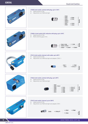
Z7600 Limit switch, vertical with plug, up to 120°C

• Splash-proof to IP 66.
• Adjustment via Z7684 test light
Z7600-4 Limit switch LED, inductive with plug, up to 100°C


• Splash-proof to IP 66.
• Work-switching gap 2 mm.
Z7615 Limit switch, internal, with cable, up to 90°C
• Splash-proof to IP 66.
• Adjustment via Z7684 test light and adapter Z7601-1.
Z7662 Limit switch, vertical with plug, up to 90°C

• Splash-proof to IP 66.

• Adjustment via Z7684 test light.
Z7675 Limit switch, internal, up to 200°C


• Splash-proof to IP 44.
• Adjustment via Z7684 test light and adapter Z7651.
Edition 4 V3 7-12-22 general 42 www.hales-asia.com.sg Strack Limit Switches

®
s t o the Tooling & Plas tic Indus tr y
PINS
Supplier
EJECTOR
P Tolerance
1-2mm -.01 6.0-12 & 15mm -.020 -.03 -.030 2-3mm -.01 14, 16 & 20mm -.020 -.03 -.040 3.1-5.9mm -.010 18 & 25mm -.007 -.020 -.020

MP01 1.0 6 4 u u MP012 1.2 6 u MP015 1.5 6 4 u u u MP020 2.0 6 4 u u u MP025 2.5 6 4 u u u u MP03 3.0 6 4 u u u u u u u u MP035 3.5 7 4 u u u u MP04 4.0 8 6 u u u u u u u u MP045 4.5 8 6 u u u MP05 5.0 9 6 u u u u u u u u MP055 5.5 10 6 u u MP06 6.0 10 6 u u u u u u u u u MP065 6.5 10 6 u u u u u u u MP07 7.0 11 6 u u u u u u u u u MP075 7.5 13 8 u MP08 8.0 13 8 u u u u u u u u u MP085 8.5 14 8 u u MP10 10.0 15 8 u u u u u u u u u MP12 12.0 17 8 u u u u u u u u u MP14 14.0 19 8 u u u u u u u u MP15 15.0 20 8 u u u u MP16 16.0 21 8 u u u u u u u u u MP18 18.0 23 8 u u u u u u MP20 20.0 25 8 u u u u u u u MP25 25.0 30 8 u u u u u u


www.hales-asia.com.sg 43 ejector pins Edition 4 V3 7-12-22
0.5 Rad + 0.0 – 0.2 H P + 0.0 – 0.2 T + 2.0 – 0.0 L Surface Hardness 70-72C P H T L Product Code PD HD HT 100 150 200 250 300 350 400 450 650 800 Core Hardness 40-45RC Material H13
JIS Straight
Nitrided Ejector Pins - Metric
100 125 150 250 Product Code P N
MP01 1.0 10 u MP012 1.2 10 u MP015 1.5 10 u u MP02 2.0 10 u MP025 2.5 10 u MP01 1.0 12 u u MP012 1.2 12 MP015 1.5 12 u u MP02 2.0 12 u u MP025 2.5 12 u MP01 1.0 25 u u MP012 1.2 25 u u MP015 1.5 25 u u u MP02 2.0 25 u u MP025 2.5 25 u u
44 www.hales-asia.com.sg ejector pins Edition 4 V3 7-12-22
+0.0 –0.05 + 0.0 – 0.2 6 + 0.0 – 0.02 3 4 S + 2 – 0 L – 0.01 – 0.02 D Surface Hardness 70-72C Core Hardness 40-44RC Material H13
MP01 1.0 50 u u u MP012 1.2 50 u u MP015 1.5 50 u u MP02 2.0 50 u u MP025 2.5 50 u u JIS Stepped Nitrided Ejector Pins - Metric
Material: WAS 1.2344 Hotwork Die Steel Standard: DIN 1530-A/ISO 6751 Hardness: Surface: Nitrided to ≥ HV 950° and Bright polished Core: Hardened throughout to ≥ 1400N/mm²

1.5 3 1.5 0.2 u u u u u 2.0 4 2 0.2 u u u u 2.2 4 2 0.2 u u u u u u 2.5 5 2 0.3 u u u u 2.7 5 2 0.3 u u u u 3.0 6 3 0.3 u u u u u u u u 3.2 6 3 0.3 u u u u u u u 3.5 7 3 0.3 u u u u u u u 3.7 7 3 0.3 u u u u u u u 4.0 8 3 0.3 u u u u u u u u 4.2 8 3 0.3 u u u u u u u 4.5 8 3 0.3 u u u u u u u
5.0 10 3 0.3 u u u u u u u u u 5.2 10 3 0.3 u u u u u u u u u
5.5 10 3 0.3 u u u u u u u u u
6.0 12 5 0.5 u u u u u u u u u u 6.2 12 5 0.5 u u u u u u u u Z92
6.5 12 5 0.5 u u u u u u u u
7.0 12 5 0.5 u u u u u u u u 7.5 12 5 0.5 8.0 14 5 0.5 u u u u u u u u u u 8.2 14 5 0.5 u u u u u u u u u 8.5 14 5 0.5 u u u u u u u u u 9.0 14 5 0.5 u u u u u u u u u 10.0 16 5 0.5 u u u u u u u u u u u 10.2 16 5 0.5 u u u u u u u u u 10.5 16 5 0.5 u u u u u u u u u 11.0 16 5 0.5 u u u u u u u u u 12.0 18/20 7 0.8 u u u u u u u u u u u 12.2 18/20 7 0.8 u u u u u u u 12.5 18/20 7 0.8 u u u u u u u u u u u 14.0 22 7 0.8 u u u u u u u u u u u 16.0 22 7 0.8 u u u u u u u u u u u 18.0 24 7 0.8 u u u u u u 20.0 26 8 1.0 u u u u u u u 25.0 32 10 1.0 u u u u u u u 32.0 40 10 1.0 u u u u u u u
www.hales-asia.com.sg 45 ejector pins Edition 4 V3 7-12-22 Straight Ejector Pins - DIN Nitrided (EP)
L + 2 Product Code D1 g6 D2 0/-0.2 K 0/-0.5 r 100 125 160 200 250 315 400 500 630 800 1000
+0 / -0.02 +0 / -0.05 +2 g6 T H P L Rz 2,5

46 www.hales-asia.com.sg ejector pins Edition 4 V3 7-12-22 Core Pins Metric (Soft Ejector JIS) Core Hardness 40-45RC P H T L PD HD HT 150 250 Material H13 Product Code MS03 3 6 4 u u MS04 4 8 6 u u MS05 5 9 6 u u MS06 6 10 6 u u MS07 7 11 6 u u MS08 8 13 8 u u MS10 10 15 8 u u MS12 12 17 8 u u MS14 14 19 8 u MS15 15 20 8 u u MS16 16 21 8 u MS18 18 23 8 u MS20 20 25 8 u 0.020 rad + 0.000 – 0.010 – 0.005 – 0.008 H P + 0.000 – 0.002 T + 0.120 – 0.000 L
Tolerances

www.hales-asia.com.sg 47 ejector pins Edition 4 V3 7-12-22 Ejector Sleeves Metric JIS N Land D B + 0.0 – 0.2 H + 0.0 – 0.05 T + 2 – 0 L ID
-0 OD
ID
+0 OD
ID
+0 OD
1.5-3mm
4-5mm -.010 +.010 -.020
3.5-5mm
6-8mm -.015 -.012 -.025
5.5-10mm
10-15mm -.020 -.015 -.030
Order: Part Number + B + D Specials to Order L Surface Hardness 70RC Core Hardness 40RC Material H13 Product Code 100 125 150 175 200 225 250 275 300 N=40 N=50 N=60 N=70 B ID D OD H T 2.0 4 8 6
2.0 5 9 6
2.0 6 10 6
2.5 5 9 6
2.5 6 10 6
3.0 5 9 6
3.0 6 10 6
3.0 7 11 6
3.5
u u u
u u u u u
u u u u u
u u u u u u
u u u u u u u
u u u u u
u u u u u
u u u u u u u
6 10 6 u u u u u u u 3.5 7 11 6 u u u u u u u 4.0 6 10 6 u u u u u MS 4.0 7 11 6 u u u u u u u u u 4.0 8 13 8 u u u u u u u u u 4.5 7 11 6 u u u u u u u 4.5 8 13 8 u u u u u u u 5.0 8 13 8 u u u u u u u u u 5.0 10 15 8 u u u u u 5.5 8 13 8 u u 6.0 10 15 8 u u u u u u u u u 6.5 10 15 8 u u u u u u u 6.5 12 17 8 u u u u 8.0 12 17 8 u u u u u u u u 10 15 20 8 u u u u u

48 www.hales-asia.com.sg ejector pins Edition 4 V3 7-12-22 Ejector Blades Metric JIS + 0.0 – 0.05 G + 2 – 0 L S B T W + 0.0 – 0.2 H D Order: Part Number +W + T + L Product Code T W D L S B G H Material SK HSI Nitrided 1 4 5 100 40 60 6 9 1 4 5 125 50 75 6 9 1 4 5 150 60 90 6 9 1 4 5 175 70 105 6 9 1.2 5 6 125 50 75 6 10 1.2 5 6 200 80 120 6 10 1.2 6 7 125 50 75 6 11 1.2 6 7 150 60 90 6 11 1.2 8 10 125 50 75 8 15 1.2 8 10 150 60 90 8 15 1.5 5 6 125 50 75 6 10 MEB 1.5 5 6 150 60 90 6 10 1.5 5 6 200 80 170 6 10 1.5 6 7 125 50 75 6 11 1.5 6 7 175 70 105 6 11 1.5 8 10 125 50 75 8 15 1.5 8 10 150 60 90 8 15 1.5 8 10 175 70 105 8 15 1.5 8 10 200 80 120 8 15 2 6 7 150 60 90 6 11 2 8 10 150 60 90 8 15 2 10 12 150 60 90 8 17 2 10 12 200 80 120 8 17 2 8 10 125 50 75 8 15
Contact . . . . . . . . . . . . . . . . . . . . . . . . . . . . . . . . . . . . . . . . . . . . . . . . . . . . . . . . . . . . . . . . . . . . . . . . . . . . . . . . . . . . . . . . . . . . . .
Reference Number: . . . . . . . . . . . . . . . . . . . . . . . . . . . . . . . . . . . . . . . . . . . . . . . . . . . . . . . . . . . . . . . . . . . . . . . . . . . . . . . . . . . .
Company Name: . . . . . . . . . . . . . . . . . . . . . . . . . . . . . . . . . . . . . . . . . . . . . . . . . . . . . . . . . . . . . . . . . . . . . . . . . . . . . . . . . . . . . .
Account Number: . . . . . . . . . . . . . . . . . . . . . . . . . . . . . . . . . . . . . . . . . . . . . . . . . . . . . . . . . . . . . . . . . . . . . . . . . . . . . . . . . . . . .
Phone: . . . . . . . . . . . . . . . . . . . . . . . . . . . . . . . . . . . . . . . . . . . . . . . . . . . Fax: . . . . . . . . . . . . . . . . . . . . . . . . . . . . . . . . . . . . . . .
www.hales-asia.com.sg 49 ejector pins Edition 4 V3 7-12-22 Custom Ejector Blade
H L 43±2 HRC M Rz4 T R D R10 Y +1.0 -0.0 +0.00 -0.02 +0.00 -0.05 +0.0 -0.2 +1.0 +2.0 59±1 HRC +0.000 -0.015 X +0.000 -0.015 D L M H T R Y X
1 micron = 0.001mm / 25.4 micron = 0.001 inches
Designation Application up to 3mm 3mm - 6mm 6mm - 10 mm 10mm - 18mm 18mm - 30mm 30mm - 50mm d9 -20 -30 -40 -50 -65 -80 -45 -60 -76 -93 -117 -142
f7 Ground Surfaces -6 -10 -13 -16 -20 -25 -16 -22 -28 -34 -41 -50
F7 Drill guides-I.D. +16 +22 +28 +34 +41 +50 +7 +10 +13 +16 +20 +25 g5 -2 -4 -5 -6 -7 -9 -6 -9 -11 -14 -16 -20 g6 Ejector Pins -2 -4 -5 -6 -7 -9 -8 -12 -14 -17 -20 -25 h4 Guide pins (die sets) 0 0 0 0 0 0 -3 -4 -4 -5 -6 -7 h5 0 0 0 0 0 0 -4 -5 -6 -8 -9 -11 h6 Punches D.C. F(pt) 0 0 0 0 0 0 -6 -8 -9 -11 -13 -16 h7 0 0 0 0 0 0 -10 -12 -15 -18 -21 -25 h9 0 0 0 0 0 0 -25 -30 -36 -43 -52 -62 h11 0 0 0 0 0 0 -60 -75 -90 -110 -210 -250 H5 +4 +5 +6 +8 +9 +11 0 0 0 0 0 0 H7 Punch guides-I.D. Reamers +10 +12 +15 +18 +21 +25 0 0 0 0 0 0 H8 Die inserts or buttonsI.D.(A&B) +14 +18 +22 +27 +33 +39 0 0 0 0 0 0 j5 +2 +3 +4 +5 +5 +6 -2 -2 -2 -3 -4 -5 j6 +4 +6 +7 +8 +9 +11 -2 -2 -2 -3 -4 -5 j7 +7 +9 +10 +12 +13 +15 -2 -3 -5 -6 -8 -10 k6 Die inserts O.D(B) +10 +12 +15 +18 +1 +1 +2 +2 m5 +7 +9 +12 +15 +17 +20 +2 +4 +6 +7 +8 +9
Edition 4 V3 7-12-22 50 www.hales-asia.com.sg
Cooling products
Table of Standard ISA Tolerances in Microns
m6 Punches E,F(shk) Dowels +9 +12 +15 +18 +21 +25 +2 +4 +6 +7 +8 +9 n6 Die inserts-O.D.(A) Guide Bushes-O.D. +13 +16 +19 +23 +28 +32 +6 +8 +10 +12 +15 +17 p6 +16 +20 +24 +29 +35 +42 +9 +12 +15 +18 +22 +26 r6 +19 +23 +28 +34 +41 +50 +12 +15 +19 +23 +28 +34 s5 +18 +24 +29 +36 +44 +54 +14 +19 +23 +28 +35 +43 s6 +22 +27 +32 +39 +48 +59 +15 +19 +23 +28 +35 +43

PRODUCTS ® Supplier s t o the Tooling & Plas tic Indus tr y
COOLING
With FCI (Flow Characteristic Indicator) Technology
Measures liquid flow rate, temperature, calculates BTU’s per minute, and Turbulent Flow. The highly-visible display is configured via the sealed push buttons and user-friendly menus.
As a diagnostic tool, engineers and maintenance personnel can quickly spot-check temperature and flow in water lines using the LCD TRACER flowmeter. This portable LCD unit is unmatched as a troubleshooting tool. As a process control tool, the TRACER can be left in place to closely monitor more critical applications. The adjustable, automatic shut-off feature prolongs battery life.
*NIST Traceable Calibration is available
Cooling products
Standard Mechanical Flowmeters
F16-A-100 F6-CL-20 F3-D3-25 FP4-A-80 1/4” through 3” NPT Flowmeters
Flow ranges from 0-1.5 gallons/minute through 50-150 gpm. Most ranges are available in liters per minute. Pressure and Temperature Gauges and quck disconnect fittings can be added to most models..
Standard Mechanical Flowmeters


Flow ranges from 0-1.5 gallons/minute through 50-150 gpm. Most ranges are available in liters per minute. Pressure and Temperature Gauges and quck disconnect fittings can be added to most models.
Click to download mechanical flowmeter catalog
Ideal for monitoring water flow and, when used with control valves, flowmeters permit precise regulation of water flow. Indicating vane visible through sight glass provides continuous flow rate and visual flow verification.
Features and Benefits
• Compact
• Rugged
• 210°F(99°C) temperature rating
• 100 psi pressure rating
• All sizes built to order for quick delivery
• Corrosion-resistant anodized aluminum body or brass end caps
• Polysulfone sight glass
• Can be mounted in any position
• Optional thermometer and pressure gauge
• Liquid-filled pressure gauge also available
• Add quick-disconnect fittings or hose barbs to sizes 1/2” or smaller
www.hales-asia.com.sg 51 Cooling products
Edition 4 V3 7-12-22 Tracer® Electronic Flowmeter
Body Size L H W C
ON T r ac e r ® 23.6 0.93 L H C W 63.5 2.5 9.7 0.38 Liquid Crystal Display NPT(F) Connection Remote Power and Switch Connection Cable (DDS models only) Remote Power and Switch Connection Cable (DDS models only) Linear = inches mm
Dimensions (mm/inches)
3/8" 87/3.42 58/2.27 42/1.67 21/0.83 2” 140/5.50 118/4.65 76/3.00 38/1.50
Durable, vane-operated devices that provide visual indication of flow rate. The indicator ball is separated from the process by a high temperature gasket and stainless steel plate. A glass window retains the indicator ball. This flowmeter is designed specifically for hot oil or hot water circulating loops in industrial processes.
• Optional Temperature Gauge provides added function.

• Temperature rating to 288˚C
• Pressure rate to 150 psi (10.34 bar)

Model HF4
Stainless steel body with 1/2”NPT connection, suitable for hot oil or pressurized water applications, 2-6gpm scale.
Model HF4
Product Code Temp. Ga. L x W x H
HF4-A-60 no 3.75 x 1.5 x 1.5 HF4-B-60 yes 3.75 x 1.5 x 1.5

Model HF8
Carbon steel body (black oxide finish) with 1”NPT connection, suitable for hot oil applications, 5-40gpm scale.
Model HF8
Product Code Temp. Ga. L x W x H
HF8-A-40 no 4.75 x 2.25 x 2.25 HF8-B-40 yes 4.75 x 2.25 x 2.25
Edition 4 V3 7-12-22 52 www.hales-asia.com.sg
Cooling products
Cooling products Hot Oil Water Flowmeters
HOW TO ORDER FR3 - B - 25 FR2 FR2B FR3 FR3B FR4 FR4B Inlet Sizes 1/4”NPT(F) 1/4”BSPP(F) 3/8”NPT(F) 3/8”BSPP(F) 1/2”NPT (F) 1/2”BSPP(F) Accessories Flow Regulator Only Thermometer (standard) Thermometer and quick change socket and plug Flow Rate (Max) 1.5 gpm (gallons per minute) 2.5 gpm 8.0 gpm 10 lpm (litres per minute) 30 lpm A B E 15 25 80 100 300 Flow 108 4.25 38.1 1.50 38.1 1.50 84 3.3 Threads per model number Adjustment Knob Max. Temperature Gauge (optional) 3/8”NPT (F) Linear = inches mm
Leak free design Solid Brass Body Needle valve vontrol Optional Temperature gauge Flow Regulators
Flow GPM W H Per Model Number Both Ends L
Smartflow Flow Regulators provide a unique, leak-free, single-point manual flow control. This regulator incorporates the proven mechanical flowmeter and integral needle valve in a compact design. Very few moving parts improve reliability and leak-free operation. Used singly or in combination with a water manifold, the flow regulator allows manual control of individual cooling water lines.
Flosense Monitor Provides visibility of key cooling circuit metrics, improves efficiency, enhances productivity and profitability.


Product Code
FFRM4-1-20 4 250 mm 205 mm 120°
FFRM4-2-40 4 250 mm 205 mm 120°

FFRM6-1-20 6 317 mm 205 mm 120° FFRM6-2-40 1"G 2-40 l/m 1/2"G 6 317 mm 205 mm 120° FFRM8-1-20 1"G 1-20 l/m 1/2"G 8 384 mm 205 mm 120°
FFRM8-2-40 1"G 2-40 l/m 1/2"G 8 384 mm 205 mm 120°
FFRM10-1-20 1"G 1-20 l/m 1/2"G 10 451 mm 205 mm 120° FFRM10-2-40 1"G 2-40 l/m 1/2"G 10 451 mm 205 mm 120°
FFRM12-1-20 1"G 1-20 l/m 1/2"G 12 518 mm 205 mm 120° FFRM12-2-40 1"G 2-40 l/m 1/2"G 12 518 mm 205 mm 120°
F4M4-1-20

www.hales-asia.com.sg 53 Cooling products Edition 4 V3 7-12-22
Flosense
Product Code Port Flow Height Length Width Max Temp
4
72
4
72
4
4
6
6
6
Product Code Input Size Readability Voltage Alarm Output FS-7100
7,1" OPC-UA 12V yes Flosense Flow Regulator
Manifold
1-20 l/m
220 155 120° F4M4HT-1-20
1-20 l/m
220 155 160° F4M4-2-40
2-40 l/m 72 220 155 120° F4M4HT-2-40
2-40 l/m 72 220 155 160° F4M6-1-20
1-20 l/m 72 287 155 120° F4M6HT-1-20
1-20 l/m 72 287 155 160° F4M6-2-40
2-40 l/m 287 155 120° F4M6HT-2-40 6 2-40 l/m 72 287 155 160° F4M8-1-20 8 1-20 l/m 72 354 155 120° F4M8HT-1-20 8 1-20 l/m 72 354 155 160° F4M8-2-40 8 2-40 l/m 72 354 155 120° F4M8HT-2-40 8 2-40 l/m 72 354 155 160° F4M10-1-20 10 1-20 l/m 72 421 155 120° F4M10HT-1-20 10 1-20 l/m 72 421 155 160° F4M10-2-40 10 2-40 l/m 72 421 155 120° F4M10HT-2-40 10 2-40 l/m 72 421 155 160° F4M12-1-20 12 1-20 l/m 72 488 155 120° F4M12HT-1-20 12 1-20 l/m 72 488 155 160° F4M12-2-40 12 2-40 l/m 72 488 155 120° F4M12HT-2-40 12 2-40 l/m 72 488 155 160°
4
Flosense
IM3-4-1/4-R 4 1/4" 3/4" 57,2 38,1 38,1 4,5 8 31 109,5
IM3-4-1/4-B 4 1/4" 3/4" 57,2 38,1 38,1 4,5 8 31 190,5
IM3-6-1/4-R 6 1/4" 3/4" 57,2 38,1 38,1 4,5 8 31 266,7
IM3-6-1/4-B 6 1/4" 3/4" 57,2 38,1 38,1 4,5 8 31 266,7
IM3-8-1/4-R 8 1/4" 3/4" 57,2 38,1 38,1 4,5 8 31 342,9
IM3-8-1/4-B 8 1/4" 3/4" 57,2 38,1 38,1 4,5 8 31 342,9
Cooling products
1" Inline Anodised Manifold

IM4-4-1/4-R 4 1/4" 1" 63,5 38,1 38,1 7 10,5 40,6 190,5
IM4-4-1/4-B 4 1/4" 1" 63,5 38,1 38,1 7 10,5 40,6 190,5
IM4-4-3/8-R 4 3/8" 1" 63,5 38,1 38,1 7 10,5 40,6 228,6
IM4-4-3/8-B 4 3/8" 1" 63,5 38,1 38,1 7 10,5 40,6 228,6
IM4-6-1/4-R 6 1/4" 1" 63,5 38,1 38,1 7 10,5 40,6 226,7
IM4-6-1/4-B 6 1/4" 1" 63,5 38,1 38,1 7 10,5 40,6 226,7
IM4-6-3/8-R 6 3/8" 1" 63,5 38,1 38,1 7 10,5 40,6 330,2
IM4-6-3/8-B
IM4-8-1/4-R
IM4-8-1/4-B
IM4-8-3/8-R
IM4-8-3/8-B
IM4-10-3/8-R
IM4-10-3/8-B
IM4-12-3/8-R
IM4-12-3/8-B
6 3/8" 1" 63,5 38,1 38,1 7 10,5 40,6 330,2
8 1/4" 1" 63,5 38,1 38,1 7 10,5 40,6 342,9
8 1/4" 1" 63,5 38,1 38,1 7 10,5 40,6 342,9
8 3/8" 1" 63,5 38,1 38,1 7 10,5 40,6 431,8
8 3/8" 1" 63,5 38,1 38,1 7 10,5 40,6 431,8
10 3/8" 1" 63,5 38,1 38,1 7 10,5 40,6 533,4
10 3/8" 1" 63,5 38,1 38,1 7 10,5 40,6 533,4
12 3/8" 1" 63,5 38,1 38,1 7 10,5 40,6 635
12 3/8" 1" 63,5 38,1 38,1 7 10,5 40,6 635
54 www.hales-asia.com.sg
products
Cooling
Edition 4 V3 7-12-22
3/4"
Anodised Manifold
Colour
L2
L1
Inline
Part No.
Ports A(BSPP) A2(BSPP)
L3
d1 d2 N L
No. Colour Ports
A2(BSPP) L2 L3 L1 d1 d2 N L
Part
A(BSPP)
A2
L
d2
A
L2 L2
A2 L3 L1
N d1 A A2 L2 L2 L A2 L3 L1 d2 N d1
IM6-4-1/2-R 4 1/2" 1-1/2" 76,2 50,8 50,8 7 10,5 57 254
IM6-4-1/2-B 4 1/2" 1-1/2" 76,2 50,8 50,8 7 10,5 57 254
IM6-6-1/2-R 6 1/2" 1-1/2" 76,2 50,8 50,8 7 10,5 57 355,6
IM6-6-1/2-B 6 1/2" 1-1/2" 76,2 50,8 50,8 7 10,5 57 355,6
IM6-8-1/2-R 8 1/2" 1-1/2" 76,2 50,8 50,8 7 10,5 57 457,2
IM6-8-1/2-B 8 1/2" 1-1/2" 76,2 50,8 50,8 7 10,5 57 457,2 IM6-10-1/2-R 10 1/2" 1-1/2" 76,2 50,8 50,8 7 10,5 57 558,8 IM6-10-1/2-B 10 1/2" 1-1/2" 76,2 50,8 50,8 7 10,5 57 558,8
IM6-12-1/2-R 12 1/2" 1-1/2" 76,2 50,8 50,8 7 10,5 57 660,4 IM6-12-1/2-B 12 1/2" 1-1/2" 76,2 50,8 50,8 7 10,5 57 660,4
SSIM4-4-1/2
SSIM4-6-1/2
SSIM4-8-1/2
SSIM4-10-1/2
SSIM4-12-1/2
SSIM5-4-1/2 4 1/2" 1-1/4" 240 50 45 50
SSIM5-6-1/2 6 1/2" 1-1/4" 340 50 45 50
SSIM5-8-1/2 8 1/2" 1-1/4" 440 50 45 50

SSIM5-10-1/2 10 1/2" 1-1/4" 540 50 45 50
SSIM5-12-1/2 12 1/2" 1-1/4" 640 50 45 50
www.hales-asia.com.sg 55 Cooling products
Edition 4 V3 7-12-22 1-1/2" Inline Anodised Manifold
A A2 L2 L2 L A2 L3 L1 d2 N d1
No. Colour Ports A(BSPP) A2(BSPP) L2 L3 L1 d1 d2 N L
Cooling products
Stainless Steel Manifolds
Part
A
A2
L B
Part No. Ports A (BSPP) A2 (BSPP) L L1 L2 B
L2
L1
B
4 1/2" 1" 240 50 45 40
6 1/2" 1" 340 50 45 40
8 1/2" 1" 440 50 45 40
10 1/2" 1" 540 50 45 40
12 1/2" 1" 640 50 45 40
Vapour flow Liquid return Heat out Heat in
Heat Transfer Rods are designed to heat or cool cones, slides and inserts. Heat Transfer Rods conduct temperature over 10,000 times faster than copper. Heat Transfer Rods operate best when 50% of the overall length is cooled using a water flow. +0.1 to +0.2mm should be up on the rod diameter for the correct fitment. Fitment hole should be drilled.
Wick
Vapour flow Liquid return Heat out Heat in
Thermal pin heat contuctor
Moulded part
Water
50 HTR2x50 HTR3x50 HTR4x50 HTR5x50 HTR6x50 HTR8x50 55 HTR2x55 HTR3x55 HTR4x55 HTR5x55 HTR6x55 60 HTR2x60 HTR3x60 HTR4x60 HTR5x60 HTR6x60 HTR8x60 65 HTR2x65 HTR3x65 HTR4x65 HTR5x65 HTR6x65 70 HTR2x70 HTR3x70 HTR4x70 HTR5x70 HTR6x70 HTR8x70 75 HTR2x75 HTR3x75 HTR4x75 HTR5x75 HTR6x75 HTR8x75 80 HTR2x80 HTR3x80 HTR4x80 HTR5x80 HTR6x80 85 HTR2x85 HTR3x85 HTR4x85 HTR5x85 HTR6x85 HTR8x85 90 HTR2x90 HTR3x90 HTR4x90 HTR5x90 HTR6x90 95 HTR2x95 HTR3x95 HTR4x95 HTR5x95 HTR6x95 HTR8x95 100 HTR2x100 HTR3x100 HTR4x100 HTR5x100 HTR6x100 105 HTR2x105 HTR3x105 HTR4x105 HTR5x105 HTR6x105 HTR8x105 110 HTR2x110 HTR3x110 HTR4x110 HTR5x110 HTR6x110 115 HTR2x115 HTR3x115 HTR4x115 HTR5x115 HTR6x115 HTR8x115 120 HTR2x120 HTR3x120 HTR4x120 HTR5x120 HTR6x120 125 HTR2x125 HTR3x125 HTR4x125 HTR5x125 HTR6x125 HTR8x125 135 HTR2x135 HTR3x135 HTR4x135 HTR5x135 HTR6x135 145 HTR2x145 HTR3x145 HTR4x145 HTR5x145 HTR6x145 HTR8x145 155
HTR2x155 HTR3x155 HTR4x155 HTR5x155 HTR6x155 165 HTR3x165 HTR4x165 HTR5x165 HTR6x165 HTR8x165 185 HTR3x185 HTR4x185 HTR5x185 HTR6x185 HTR8x185 205 HTR3x205 HTR4x205 HTR5x205 HTR6x205 HTR8x205
Edition 4 V3 7-12-22 56 www.hales-asia.com.sg Cooling products Heat Transfer Rods
2mm 3mm
mm
4mm 5mm 6mm 8mm Length in Diameters and Catalogue Numbers Water Moulded part Thermal pin heat contuctor Wick
200 Series plugs are also available with an internal shut-off valve.
300 Series plugs are also available with an internal shut-off valve.
CM251 (20NR1/8) 200 1/8 9 17 22 25
CM252 (20NR1/4) Series 1/4 9 19 26 29
CM253 (20NR3/8) 1/4 Flow 3/8 9 19 30 30
CM351 (30NR1/8) 300 1/8 13 25 26 35
CM352* (30NR1/4) Series 1/4 13 25 26 35
CM353* (30NR3/8) 3/8 Flow 3/8 13 26 30 38
CM354 (30NR1/2) 1/2 13 28 37 42
CM552 (50NR1/4) 500 1/4 20 37 30 41
CM553 (50NR3/8) Series 3/8 20 37 32 41
CM554 (50NR1/2) 1/2 Flow 1/2 20 38 32 39
CM556 (50NR3/4) 3/4 20 38 38 45
* Also available with internal valve, specify “V”
Female Brass Connectors


COOLING PRODUCTS
CM251F (20NR1/8I) 1/8 6 9 28 13
CM252F (20NR1/4I) 200 Series 1/4 6 9 32 17
CM253F (20NR3/8I) 3/8 6 9 34 19
CM352F (30NR1/4I) 1/4 9 13 37 17
CM353F (30NR3/8I) 300 Series 3/8 9 13 39 19
CM354F (30NR1/2I) 1/2 9 13 46 24
www.hales-asia.com.sg 57 Cooling products Edition 4 V3 7-12-22 A R d1 d H L R d1 SW d L A R d1 d H L R d1 SW d L
Series R (BSPT) D1 H A L
Product Code
d
SW
Product Code Series R Thread
d1 L
Male
Brass Connectors
200
Product Code L T d d1 A
CM251212
2 1/2 1/8 1/4 3/8 11/16
CM2514 4 1/8 1/4 3/8 1 CM251512 5 1/2 1/8 1/4 3/8 1
CM2517 7 1/8 1/4 3/8 1 CM251812 8 1/2 1/8 1/4 3/8 1
CM252212 2 1/2 1/4 1/4 3/8 7/8
CM2524 4 1/4 1/4 3/8 1 1/4 CM252512 5 1/2 1/4 1/4 3/8 1 1/4
CM2527 7 1/4 1/4 3/8 1 1/4 CM252812 8 1/2 1/4 1/4 3/8 1 1/4 CM253212 2 1/2 3/8 1/4 3/8 1
CM2534 4 3/8 1/4 3/8 1 1/4 CM253512 5 1/2 3/8 1/4 3/8 1 1/4 CM2537 7 3/8 1/4 3/8 1 1/4

Product Code L T d d1 A
CM351212
2 1/2 1/8 3/8 1/2 7/8
CM3514 4 1/8 3/8 1/2 1 CM351512 5 1/2 1/8 3/8 1/2 1
CM3517 7 1/8 3/8 1/2 1 CM351812 8 1/2 1/8 3/8 1/2 1
CM352212 2 1/2 1/4 3/8 1/2 7/8
CM3524 4 1/4 3/8 1/2 1 1/4
CM352512 5 1/2 1/4 3/8 1/2 1 1/4
CM3527 7 1/4 3/8 1/2 1 1/4
CM352812 8 1/2 1/4 3/8 1/2 1 1/4
CM35210 10 1/4 3/8 1/2 1 1/4
CM3534 4 3/8 3/8 1/2 1
CM353512 5 1/2 3/8 3/8 1/2 1 1/4
CM3537 7 3/8 3/8 1/2 1 1/4 CM35310 10 3/8 3/8 1/2 1 1/4
Edition 4 V3 7-12-22 58 www.hales-asia.com.sg Cooling products Brass Extension Plugs
Series 1/4 Flow
Series 3/8 Flow
300
Height H T 15/8 L A d1 d
(20K6)
(30K10)
(30K13)
(20K6V)


(30K10V)
(30K13V)
Cooling products Cooling products Cooling products www.hales-asia.com.sg 59 Edition 4 V3 7-12-22 90° Hose Tail Coupling - International Series 45° Hose Tail Coupling - International Series L L1 A D D L A L1 D L A L1 SW L L1 A D A L SW L1 D L L1 A D D L A L1 D L A L1 SW L L1 A D A L SW L1 D L L1 A D D L A L1 D L A L1 SW L L1 A D Product Code Product Code Product Code Hose Flow L D Series without Valve with Valve Valve Seal Only ID
CM206
CM206V
200V 3/8 1/4 51mm 17 200
Product Code Product Code Hose Flow L L1 D Series without Valve with Valve ID
3/8 1/4 40mm 22mm 17 200
300
Product Code Product Code Hose Flow L L1 D Series without Valve with Valve ID
CM226V
3/8 1/4 55.5mm 22mm 18 200
CM328V
1/2 3/8 75mm 25mm 24 300
CM526V
3/4 5/8 77mm 30mm 32 500 Straight Coupling - International Series
CM306
CM306V
300V 3/8 1/4 64mm 23 300 CM308
CM308V
300V 1/2 3/8 66.5mm 23 300 CM308SL CM308VSL 300V 1/2 3/8 73mm 23 300 CM506 (50K19) CM506V (50K19V) 500V 3/4 5/8 89mm 30 500
CM216 (20K10/90) CM216V (20K10/19)
CM318 (30K13/90) CM318V 1/2 3/8 56mm 28.5mm 23
CM516 (50K19/90) CM516V 3/4 5/8 77mm 32mm 30 500
CM226 (20K10/45)
(20K10/45V)
CM328 (30K13/45)
(30K13/45V)
CM526 (50K19/45)
(50K19/45V)


60 www.hales.com.au Cooling products 60 www.hales-asia.com.sg Cooling products Edition 4 V3 7-12-22 Plugs Quick Connect Water Jumpers L M Twist lock sleeve prevents accidental disconnect seals A Product Code FHS Series Hose ID L C M A WJ200-6 200 3/8 1 1 1/4 3/8 5/8 WJ300-6 300 3/8 1 7/16 1 9/16 1/2 7/8 WJ300-8 300 1/2 1 7/16 1 9/16 1/2 7/8 Hales Water Jumpers offer smooth unrestricted flow paths and consistent cooling flow rate, eliminating crimped hoses. Hose ID C L M Twist lock sleeve prevents accidental disconnect Viton seals A Hose ID C L M Twist lock sleeve prevents accidental disconnect Viton seals S10-1 10mm S6 6mm S8 8mm Product Code D KN105-8 6mm Product Code D R1/4 1/4 R1/8 1/8 Product Code D Channel Plug Equivalent Pressure Plugs Channel Plug Equivalent Pressure Plugs Threaded Conical Plug Equivalent


Cooling products Cooling products Cooling products www.hales-asia.com.sg 61 Edition 4 V3 7-12-22 90° Hose Tail Coupling - European Series 45° Hose Tail Coupling - European Series Straight Coupling - European Series L L1 A D D L A L1 L A L1 D D L SW L1 A D L1 L SW D L1 L SW D A 09K10 10 18 52 22 609K10V 10 18 52 22 6 + 13K13 13 23 61,5 25 913K13V 13 23 61,5 25 9 + Product Code A D L L1 Flow Valve L L1 A D D L A L1 L A L1 D D L SW L1 A D L1 L SW D L1 L SW D A 09K10-45 10 18 41 22 609K10V-45 10 18 41 22 6 + 13K13-45 13 23 51 25 9Product Code A D L L1 Flow Valve 09K10-90 10 18 41 22 609K10V-90 10 18 41 22 6 + Product Code A D L L1 Flow Valve L L1 A D D L A L1 L A L1 D D L SW L1 A D L1 L SW D


62 www.hales.com.au Cooling products 62 www.hales-asia.com.sg Cooling products Edition 4 V3 7-12-22 cooling products Extended Connector - European Series L L1 A D D L A L1 L A L1 D D L SW L1 A D L1 L SW D L1 L SW D A D D L SW L1 A D L1 L SW D L1 L SW D A 09KUR1/4 G1/4 18 48 9 17 609KUR1/4V G1/4 18 48 9 17 6 + 13KUR3/8 G1/3 23 51,5 9 22 9Product Code A D L L1 SW Flow Valve D L A L1 L A L1 D D L SW L1 A D L1 L SW D L1 L SW D A 09N100 8 9 100 79 9 609N120 10 9 120 100 11 613N150 14 13,5 150 125 15 9Product Code A D L L1 SW Flow Valve Product Code A D L L1 SW Flow Valve 09NM10 M10x1 9 24 7 11 609NR1/4 G1/4 9 26 9 15 609NR1/8 G1/8 9 24 7 11 609NR3/8 G3/8 9 30 10 17 613NR1/4 G1/4 13,5 26 9 15 913NR1/8 G1/8 13,5 25 8 14 9Male Thread Coupling - European Series Male Connector - European Series
Product
I.D. O.D.
G13R 13mm 21mm 50m RED 90° 100°
E10B 10mm 16.5mm 50m BLUE 60° 160°

E10R 10mm 16.5mm 50m RED 60° 160°
E13B 13mm 21mm 50m BLUE 90° 160°

E13R 13mm 21mm 50m RED 90° 160°
G19B 19mm 27mm 30m BLUE 110° 100°

G19R 19mm 27mm 30m RED 110° 100°
Crimper
Ferrules Product Code Crimp Range. X100 10-36 mm Product Code D d. Suits Hose C10/17 17.5mm 10mm G10/E10 C13/22 22.5mm 13mm G13/E13 C19/29 29mm 19mm G19/E19

Cooling products
www.hales-asia.com.sg 63 Edition 4 V3 7-12-22 Hose
Cooling products
Cooling products
Code
Length
Simple to use bench mounted hand crimping machine. Fast effective crimps, Ideal for water circuits. Suitable for up to 3/4" hose, usable with ferrules with an outer diameter of 10 - 36 mm. Bend Radius
Colour
Max Temp
G13B 13mm 21mm 50m BLUE 90° 100°
Steel Ferrules for use with
Hand
Stainless
Hand Crimper.
MOULDING

® Supplier s t o the Tooling & Plas tic Indus tr y
ACCESSORIES
MOULDING ACCESSORIES
MOULDING
• Simultaneous digital setpoint and digital temperature indication.

• Accepts Type J or Type K thermocouple input (jumper selectable).


• Auto-tuning, with adjustable proportional band and rate.
• Bumpless auto/manual transfer.
• CompuStep bake out feature prevents moisture at start-up.
• Built-in loop break, short, open, and reverse thermocouple protection.
• Optional triac failure protection.
• Preset alarms at 30°F (17°C).
• Jumper-selectable self-start mode.
• Current monitor feature displays average current to load.
• CE-compliant.
MOULDING ACCESSORIES 64 www.hales-asia.com.sg
ACCESSORIES Edition 4 V3 7-12-22 Product Code Description PIM1BX10 10 Amp Unit Single Zone Temperature Control System
Zone Temperature
16 to 48 Zone Mainframes are also available to order. 30 Amp option also available. Modules sold separately. Product Code Description MFFMP2 2 Zone Mainframe MFFMP3 3 Zone Mainframe MFX5 5 Zone Mainframe MFX8 8 Zone Mainframe MFX12 12 Zone Mainframe RMA Modular
Multi
Control System
Product Code RMAX15


MOULDING ACCESSORIES MOULDING ACCESSORIES MOULDING ACCESSORIES www.hales-asia.com.sg 65 Edition 4 V3 7-12-22 METICOM Temperature Controller 1 & 2 Zone Modular Terminal Mounting Box Product Code Rows Pin Box Dimension 79-010-501 1 1 x 5 pin L175 x W62 x H65 79-010-502 1 2 x 5 pin 79-010-508 1 1 x 16 pin 79-010-512 1 1 x 24 pin No. of Zones Description Mastip Code Power Input Output Connector Power Connector TC Connector 1 CIS - 1 79-060-010 230V 1P 1 x 5 Pin Female Single Latch, Power & TC Combination 2 CIS - 2 79-060-020 230V 1P 2 x 5 Pin Female Single Latch, Power & TC Combination * Dimension : 193 x 71 x 225mm Modular Terminal Mounting Box Product Code Rows Pin Box Dimension 79-010-608 2 2 x 16 pin L175 x W124 x H65 79-010-609 2 1 x 16, 1 x 25 pin 79-010-612 2 2 x 24 pin 79-010-613 2 1 x 24, 1 x 25 pin


Edition 4 V3 7-12-22 MOULDING ACCESSORIES 66 www.hales-asia.com.sg MOULDING ACCESSORIES MOULDING ACCESSORIES Product Code International Code Pin Box Dimension L x W x H Screw Distance X Y 79-010-701 PTC5TB 1 x 25, 1 x 10 pin 220 x 70 x 108mm 204mm 38mm 79-010-702 PTC8TC 1 x 25, 1 x 16 pin 240.5 x 70 x 108mm 224.6mm 38mm 79-010-703 PTC12TB 1 x 25, 1 x 24 Pin 267.5 x 70 x 108mm 251.6mm 38mm USA style Mounting Box Blank Panel Must be used to cover unused zones in main frames. Supplied with push-pull panel fasteners. Product Code MFBP Universal Floor Stand Product Code Zones MFS5812 Adjustable for 5, 8 & 12 zone


MOULDING ACCESSORIES www.hales-asia.com.sg 67 Edition 4 V3 7-12-22
Power/Input Connectors Connectors and Single Zone Plugs Product Code Description Zones MTC5 Mould Thermocouple Connecter 5 Zones MTC8 Mould Thermocouple Connecter 8 Zones MTC12 Mould Thermocouple Connecter 12 Zones Thermocouple Connector Product Code Description Zones PIC5 Mould Power Connecter 5 Zones PIC8 Mould Power Connecter 8 Zones PIC12 Mould Power Connecter 12 Zones CKPTM1 Cable, Frame End 5-Pin Combo Mold Power/ Thermocouple Connectors Product Code CKPTM-1 CKPTOC1 Frame 5-Pin Combo Mould Power/ Thermocouple Connectors Product Code CKPTOC-1
Cable, Mould-End 5-Pin Combo Mold Power/ Thermocouple Connectors Product Code CKPTF-1
Mould
CKPTF1


MOULDING ACCESSORIES 68 www.hales-asia.com.sg Edition 4 V3 7-12-22 CKPTIC1 Mould 5-Pin Combo Mold Power/ Thermocouple Connectors Product Code CKPTIC-1 Single Zone Plug & Cables Combination Cables 5 pin combination Thermocouple/Power Cable. Power Cables Thermocouple Cables Product Code Zones Length TC5C10 5 Zones 10’ TC5C20 5 Zones 20’ TC8C10 8 Zones 10’ TC8C20 8 Zones 20’ TC12C10 12 Zones 10’ TC12C20 12 Zones 20’ Product Code Zones Length MPC5C10 5 Zones 10’ MPC5C20 5 Zones 20’ MPC8C10 8 Zones 10’ MPC8C20 8 Zones 20’ MPC12C10 12 Zones 10’ MPC12C20 12 Zones 20’ Product Code Length MPTC10 10’ MPTC20 20’ Module Fuses Product Code Amps ABC10 10 ABC15 15 Connector Crimps Product Code Amps HWCC-1 15 HWCC-2 30
Tool & Die Parts Cleaner A heavy duty formulation designed to clean injection mould, tools and dies after production runs and prior to commencement of new jobs.
Tool & Die Protector A heavy duty formulation designed to protect tools, injection moulds and dies from oxidisation and rusting during storage in between production runs. Penetrates tools and mould removes moisture from cavities and mould. Leaves a protective film of lubrication oils and a rust preventative coating.
Product Code
DIE CLEANER
Size
400g Aerosol

DIE PROTECTOR 400g Aerosol

Silicone Mould Release
A proven release agent to prevent sticking in mould cavities
Paintable Mould Release
A premium quality release agent which enables plastic parts to be printed, painted, hot stamped, vacuum plated and metalised
Product Code Size
SILICONE MOULD
300g Aerosol
PAINTABLE MOULD 300g Aerosol

Min-Lube™ High Performance Lubricating Grease

Min-Lube grease is designed specifically for lubrication in severe environments as well as food and pharmaceutical related industries. It is a mineral oil base thickened with a proprietary calcium sulfonate complex, and a carefully selected additive package focused on thermal, oxidative, and mechanical stability. It contains Micronox® to provide antimicrobial protection, which is groundbreaking technology that prevents degradation of the lubricant.
Zap-Ox®

Removes all rust, oxidation, buildup, stains, weld discolouration and more

Nano Mold Coating®
Releases plastic parts for up to 300,000 cycles, part design dependant. Reduces cycle times, semi permanent.
Product Code
NANO-FG-10ML-KIT

MOULDING ACCESSORIES www.hales-asia.com.sg 69 Edition 4 V3 7-12-22
Code
Pack Size
Product
Description
NANO-ZO-16 Zap-Ox Cleaner 475ml Bottle
Specialty Lubricants & Fluids
Food Grade Ejector Pin Lubricant
Ejector Pin Lubricant
Non-soiling lubricants that keep moving parts running smoothly and prevent damage due to breakage and seizing.
Copper Anti-Seize Assembly Compound
Mouldpro Copper Anti-Seize ensures rapid and easy assembly of threaded parts. It allows correct torque to be applied by eliminating thread interference.
Mould Polish

This superior quality mould polish is perfect for cleaning and polishing steel moulds. It safely and easily removes oxidation, corrosion, stains and rust. It produces a brilliant reflective lustre and leaves an invisible protective coating to ensure a long lasting shine.

Mould Cleaner Wipes
Mould Cleaner Wipes are specifically developed for cleaning and degreasing of mould surfaces.


• Ultra-low linting non-abrasive wipe

• Leaves no residue
Product Code Size MLF500FG 500g tub MLF080FG 80g tube Product Code Size MCS 500 500g tub MCS 80 80g tube Product Code Size MCP 80 80g tube Product
Food Safe Purging it P&P Cream
P&P Cream™ is specific for the cleaning of screws, cylinders, nozzles, hot runners, extrusion dies, moulds and any metal surface. Removes charred residue, black spots, colored pigments and all left over material deposits, for all thermoplastic and thermosetting. Working temperature between 70°c and 420°c,
(Min order 4)
Edition 4 V3 7-12-22 MOULDING ACCESSORIES 70 www.hales-asia.com.sg Specialty Lubricants and Fluids
Code Size WMC80 Tub of 80 wipes
Specialty Lubricants & Fluids
Product Code Size PURGE Sachet


MOULDING ACCESSORIES www.hales-asia.com.sg 71 Edition 4 V3 7-12-22
Code d1 k Weight
Product
Product Code d1 d2 s Weight
MC-SB-M12x50 36 mm 10 mm 110 g MC-SB-M16x62 45 mm 13 mm 240 g MC-SB-M20x62 50 mm 13 mm 320 g MC-SB-M24x116 50 mm 14 mm 555 g
MC-TW-M12 13 mm 35 mm 5 mm 30 g MC-TW-M16 17 mm 45 mm 6 mm 60 g MC-TW-M20 21 mm 50 mm 6 mm 70 g MC-TW-M24 25 mm 60 mm 8 mm 140 g
•
•
Product Code SW e m r Weight
mm
C E D G F A B H Product Code Model A B C D E F G H MC12 M12 x 100mm 100 32 19 71 43 88 13 M12 MC16 M16 x 150mm 150 37 25 100 60 130 17 M16 MC20 M20 x 200mm 200 50 32 114 82 185 21 M20 MC25 M25 x 250mm 250 70 45 157 100 224 27 1”BSW
•
•
Nuts, Bolts, Washers and Clamps
Hexagon Nut
Hardened
Black Coating Clamp Support Bolt • Black Coating
MC-HN-M12 19
21.9 mm 18 mm 17 mm 25 g MC-HN-M16 24 mm 27.7 mm 24 mm 22 mm 55 g MC-HN-M20 30 mm 34.6 mm 30 mm 27 mm 110 g MC-HN-M24 36 mm 41.5 mm 36 mm 32 mm 190 g
Slotted Clamp
Black Coating Thick Washer • Hardened
Black Coating
MOULDING ACCESSORIES
Prevent Plastic Parts scattering around with Scatterguard
The patented design contains the ejected parts within the mould area whilst the roller blind action allows a completely unrestricted view of the mould face and allows easy access to the mould.
• Ultra Low Profile Design
• Crystal Clear Mould Screen

• Reduce Scrap by Eliminating Contamination
• Increase Profits
• Ideal for Cleanroom Applications
MOULDING ACCESSORIES
UniVest®: For Plastic Processors
Insulation Barrel Blankets & UniVest


UniVest® insulation jackets provide a low-cost solution for reducing energy costs, and shortening start-up time between jobs by retaining heat inside barrels, extruders, dies and hoses. This will lower the ambient temperature in your facility, and lower the overhead cost for equipment operations and air conditioning Features

• High temperature strap and buckle fastening system

• PTFE coated exterior
• Withstand temperatures up to 1200°F
• High density ceramic fibre insulation Benefits
• Improves equipment process
• Protects employees and equipment
• No equipment downtime
• Simple and quick installation
• Reduces energy consumption
• 100% Asbestos free.
Edition 4 V3 7-12-22 72 www.hales-asia.com.sg
Product Code Mould Height Max. Width
20 cm 55 cm SG-2 30 cm 55 cm SG-3 40 cm 55 cm SG-4 50 cm 55 cm SG-5 60 cm 55 cm Mould Curtain
SG-1

®
s t o the Tooling & Plas tic Indus tr y
RUNNER & CONTROL
Supplier
HOT


www.hales-asia.com.sg 73 Hot runner and control Edition 4 V3 7-12-22 SX Nozzle With two heaters the SX nozzle is perfectly suited for all single nozzle applications. Independently controlled heater zones provide uniform temperature distribution along the length of the nozzle, making it ideal to process difficult plastics.
Options Multi-Hole Torpedo Tip One-Hole Torpedo Tip Open Tip Extended Tip Open Nut Bush Nut Sprue Nut Ø d2 d3 L5 L4 A L 13 Series 16 Series 19 Series 27 Series 45 45 55 55 55 65 65 65 75 75 75 75 L 95 95 95 95 115 115 115 115 145 145 175 175 225 275 L4 18 18 20 25 L5 44 44 46 50 d2 40 40 50 50 d3 27 30 33 43 A 10 12 15 23 All measurements are in millimetres
Gating
Gating

74 www.hales-asia.com.sg Hot runner and control Edition 4 V3 7-12-22 MX Nozzle Low moulding temperature and pressure, excellent temperature consistency and front loading capabilities, that’s the Mastip MX nozzle, specifically designed for multi cavity manifold systems and hot halves. The MX nozzle is suited for small to medium applications in all types of markets. It is able to process a wide range of plastics, from the easy ethylenes to tough
resins.
engineering
Options Multi-Hole Torpedo Tip One-Hole Torpedo Tip Open Tip Extended Tip Open Nut Bush Nut Sprue Nut Valve Gate Open tip Valve Gate Torpedo Tip A/F L4 L Ad3 Ø d2 13 Series 16 Series 19 Series 45 45 55 55 55 65 65 65 75 75 75 L 95 95 95 115 115 115 145 145 145 175 175 175 A/F 24 26 36 d2 28 30 40 d3 22.9 24.9 31.5 L4 12 12 15 A 10 12 15 All measurements are in millimetres

www.hales-asia.com.sg 75 Hot runner and control Edition 4 V3 7-12-22 BX Nozzle Gating Options A/F L4 L Ad3 Ø d2 Multi-Hole Torpedo Tip Open Tip Extended Tip One-Hole Torpedo Tip Open Nut Bush Nut Sprue Nut Valve Gate Torpedo Tip Valve Gate Open tip A/F L4 L Ad3 Ø d2 Multi-Hole Torpedo Tip Open Tip Extended Tip One-Hole Torpedo Tip Open Nut Bush Nut Sprue Nut Valve Gate Torpedo Tip Valve Gate Open tip 13 Series 16 Series 19 Series 27 Series 45 45 55 55 55 65 65 65 75 75 75 75 L 95 95 95 95 115 115 115 115 145 145 145 145 175 175 175 175 225 A 10 12 15 23 A/F 31 34 36 45 d2 34 38 40 50 d3 27 30 33 43 L4 12 12 15 20 BX nozzle is designed to provide a cost sensitive solution to single & multicavity applications. All measurements are in millimetres
Sporting an extremely compact design, the VeriShot™ system greatly reduces mold height requirements as it doubles as a locating ring housing the mechanics. This ensures perfect alignment between mold and machine platens. VeriShot™ is compatible with TX16, TX19 and TX27 FlowLoc™ nozzles, which screw directly into the lower manifold providing a secure, leak-proof solution.
• Stainless Steel construction for maximum service life

• Reduced mould height at 54mm+ nozzles.
• Location ring can be sized to your requirement

76 www.hales-asia.com.sg Hot runner and control Edition 4 V3 7-12-22 VeriShot™-Single Valve Gate 16 Series 19 Series 27 Series Model SVG SVG SVG Actuation Type Pneumatic Pneumatic Pneumatic Pin Size 2.5 3.0 5.0 Stroke 10 10 10 Valve Gate Assembly Gating Options Open Nut Bush Nut Sprue Nut Valve Gate Torpedo Tip Valve Gate Open tip Ø70 OL SVG 102 REF 10 BX Nozzle Ø75 L
All measurements are in millimetres FlowLoc Nozzle Compatability 16 Series 19 Series 27 Series L 75 75 75 85 85 85 95 95 95 105 105 105 115 115 115 130 130 130 145 145 145 160 160 160 175 175 175 200 200 200 225 225 250 250 275 275 300 300 350 400 450

www.hales-asia.com.sg 77 Hot runner and control Edition 4 V3 7-12-22 MVG Valve Gate L L4 A/F Blanking Plate Ø 54.0 50.0 Min 10.0 Cylinder Assembly Spacer Valve Pin Ø d2 Open Nut Bush Nut Sprue Nut Torpedo L L4 d3 d1 A/F Blanking Plate Ø 54.0 50.0 Min 10.0 Cylinder Assembly Spacer Valve Pin Ø d2 Open Nut Bush Nut Sprue Nut Valve Gate Torpedo Tip Valve Gate Open tip Gating Options MX BX MX BX 13 Series 16 Series 45 45 45 45 55 55 55 55 65 65 65 65 L 75 75 75 75 95 95 95 95 115 115 115 115 145 145 145 145 175 175 175 175 A/F 24 31 26 34 d1 10 10 12 12 d2 28 34 30 38 d3 22.9 27 24.9 30 L4 12 12 12 12 L d3 d1 50.0 Min 10.0 Open Nut Bush Nut Sprue Nut Valve Gate Torpedo Tip Valve Gate Open tip 13 Series * MX / BX 16 Series MX / BX Valve Gate Assembly Model MVG25 - 2.0 MVG25 - 2.5 Actuation Type Pneumatic Pneumatic Pin Size 2.0 2.5 Stroke 7 7 * 13 Series available in open nut and open tip only All measurements are in millimetres
Standard Layouts, Exceptional Results
Mastip has an extensive range of standard or customized manifold designs that ensure cavity-to-cavity consistency through the normal or theological balancing of flow channels.


Each manifold incorporates durable, high quality components that deliver fast cycle times, precise gate control and superior quality parts.
Durable, Long-lasting Components
All manifolds are equipped with superior components including pressed-in heaters, ceramic connectors and high quality mould base or stainless steel plates, enabling them to perform under the most demanding applications and conditions.
Mastip’s manifold range is further complimented by the industry leading X-Range nozzles and the extensive range of tip and nut combinations to deliver high performing, durable solutions able to meet the demands of the most abrasive and difficult to mould resins.
Manifold systems to suit all your moulding requirements
Mastip’s experienced teams can design and manufacture manifold systems to suit all your moulding requirements. All Mastip manifolds are designed to deliver a uniform melt to each nozzle, ensuring cavity-to-cavity consistency. This is achieved through natural balancing of the flow channels and ensuring constant temperature profiles are maintained across the manifold block. Small cavity or high cavity systems, simple single level or complex multi-level stack systems, thermal gate or valve gate systems, Mastip can provide you with a Manifold system to meet your requirements in standard high quality mould base steel or stainless steel plates.
Scan this QR code to go to website for further information:
Designed, Manufactured and Tested
Every manifold goes through extensive design and analysis to ensure the following:

• optimised melt delivery
• improved production efficiencies
• perfect cavity-to-cavity filling
• excellent gate quality
78 www.hales-asia.com.sg Hot runner and control Edition 4 V3 7-12-22 Standard
Manifold System
Designed, Manufactured and Tested
Every high-cavity manifold goes through extensive design and analysis to ensure the following:


• optimise melt delivery
• balanced cavity-to-cavity filling
• excellent gate quality
• optimise thermal profile
Incorporating M-Series Multi-Cavity Nozzles
Specifically designed for multi-cavity systems, the MX and MJ nozzle series are simple to install, front-loading for ease of servicing and ideal for close-pitch gating due to small gate pocket requirements.
MX and MJ nozzles have superior thermal insulation and precise temperature control to optimise cycle times and are available in sizes ranging from 45-175 mm.
High cavity single or multi-level systems

Mastip’s expert teams can design and manufacture high cavity single or multi-level systems, with thermal or valve gates. Our systems are designed and manufactured to the highest level of quality, delivering a uniform melt to each nozzle, ensuring cavity-to-cavity consistency. This is achieved through natural balancing of the flow channels and ensuring constant temperature profiles are maintained across the manifold block. Mastip can provide you with a Manifold system to meet your requirements in standard high quality mould base steel or stainless steel plates.
Scan this QR code to go to website for further information:
Guaranteed to Perform
Mastip Hot Half systems are backed by a 3 year leak-proof guarantee, available in thermal or valve gate configurations and delivered as a complete solution to integrate seamlessly into your mould.
Include a Meticom Temperature Controller with your Hot Half System order and we will extend the warranty on the Mastip Hot Half System from 3 to 5 years. See page 10 for more information
www.hales-asia.com.sg 79 Hot runner and control Edition 4 V3 7-12-22 High Cavity Manifold System
Unique Designs for Multi-Component Moulding
Multi-material moulding is a common way to create parts with two or more types of material in order to provide stability, functionality or aesthetic appeal over traditional single type material parts. Common examples of this include razor and toothbrush handle grips.
Often referred to as multi-shot, coinjection or over-moulding, multi-material solutions are typically uniquely designed systems providing an effective and costefficient way to produce custom parts requiring multiple types of material or

Designed, Tested and Supported
Mastip works closely with our customers to design customised solutions that solve their unique requirements for multimaterial moulding.
Each system is supplied with installation and mould recommendations and backed by our global service and support network.
From Simple to Technically Advanced Multi-Material Systems
Mastip has extensive experience in supplying solutions for multi-material and multi-colour applications. Whether it is over moulding soft grips or different colours on single part, Mastip has the technology and technical expertise to develop the right multi-material hot runner solution for your needs. From simple high cavity plastic packaging to technically advanced components such as structural and engineering parts for the automotive industry, incorporating Mastip’s multi-material systems into your mould can simplify your production, deliver quality parts and save you time and money on your product assembly.
Scan this QR code to go to website for further information.
Durable, Long-lasting Components
All manifolds are equipped with superior components including pressed-in heaters, ceramic connectors and high quality mould base or stainless steel plates, enabling them to perform under the most demanding applications and conditions.

Mastip’s manifold range is further complimented by the industry leading X-Range nozzles and the extensive range of tip and nut combinations to deliver high performing, durable solutions able to meet the demands of the most abrasive and difficult to mould resins.

80 www.hales-asia.com.sg Hot runner and control Edition 4 V3 7-12-22 Multi Material Manifold System
Nexus™ systems are designed for fast, simple installation out of the box without requiring any further assembly
Nexus™ systems feature fully customisable frames, electrical connections, tip and nut options and nozzle lengths to suit your application requirements.

Cylix™ Valve Gate Actuation
The Cylix™ Cylinder features Pneumatic Valve actuation in a thermally stabilized system mounted directly to the manifold. With the ability to adjust valve pin height and incorporating long life seals and bearings, it is the optimal solution for precise control of your moulding requirements.
Nexus™ System with FlowLoc™ Nozzle

The FlowLoc nozzle range features a threaded base that attaches to the manifold providing a secure, leak-proof operation. With advanced heating technology, the FlowLoc delivers superior thermal performance for a wide moulding window
Ready
SetInject
Following on from the ground breaking success of Mastip’s Nexus Thermal Gate we are proud to introduce the Nexus Valve Gate with Cylix actuation.

Mastip’s next generation Nexus™ Systems are delivered Pre-Assembled and PreWired as a complete turn-key solution for quick and simple installation.
Both the Nexus Thermal Gate and the Nexus Valve Gate Systems incorporate the advanced leak protection of FlowLoc™ Technology.
Scan this QR code to go to website for further information
All measurements are in millimetres.
* Further nozzle lengths are available on request
www.hales-asia.com.sg 81 Hot runner and control Edition 4 V3 7-12-22
AUSTRALIA


CONTACT HALES www.hales-asia.com.sg chris@hales-asia.com.sg SINGAPORE
Hales Asia Pte Ltd 2 Ang Mo Kio Street 64 #04-03F Econ Industrial Building Singapore 569084 Tel: +65 6754 7077 Fax: +65 6754 7177
GLOBAL STRENGTH LOCAL KNOWLEDGE
ASIA EDITION 2
Hales Australia Pty Ltd 45 Woodlands Drive Braeside Victoria 3195 Phone : +61 3 8587 1600
HALES
ASIA CATALOGUE
HALES