


Series
AMH = ADP Mobile Home Furnace Revision
Blower Motor
E = 5-speed ECM motor
Cabinet N = Not Included Unit Size
2 = 2 Ton Voltage
3 = 3 Ton
4 = 4 Ton
5 = 5 Ton
Configuration
D = Downflow
Electric Heat Available In:
00 = No heat Size 2-5 Ton
05 = 5.0 kW Size 2-5 Ton
07 = 7.5 kW Size 2-5 Ton
10 = 10 kW Size 2-5 Ton
12 = 12.5 kW Size 3-5 Ton
15 = 15 kW Size 3-5 Ton
20 = 20 kW Size 4-5 Ton
Series MH = Mobile Home
Accessory
= 120 V, 60 Hz, 1 ph., with time delay
= 208/240 V, 60 Hz, 1 ph., with time delay
Line Voltage Connection
= Stripped Wires
= Circuit Breaker
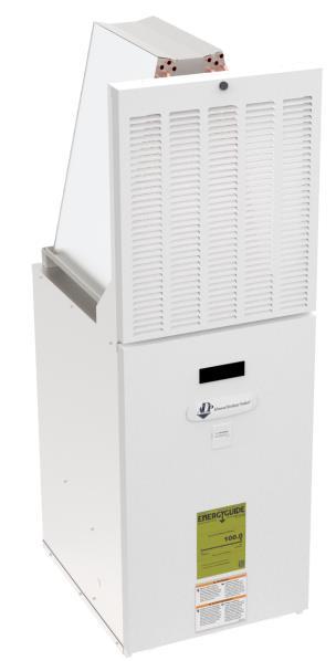
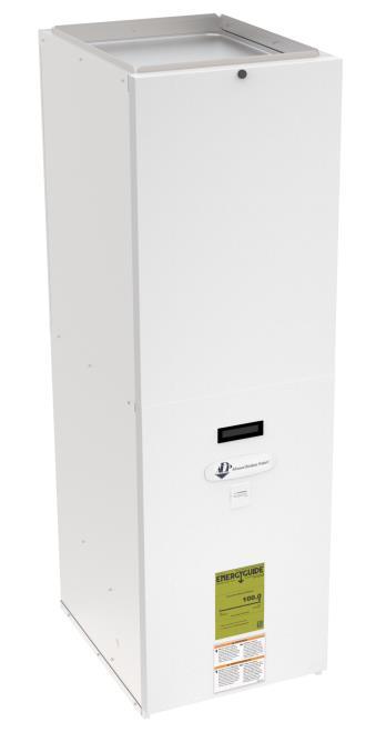
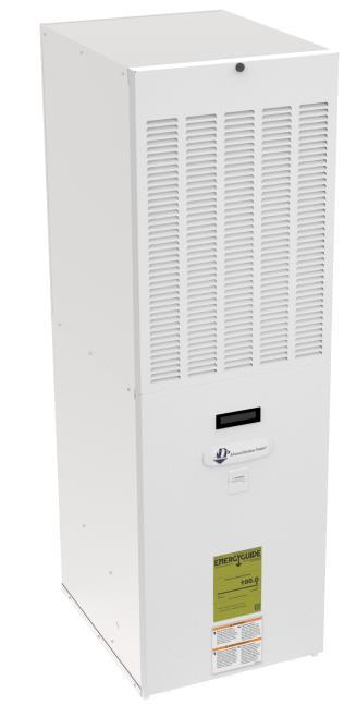
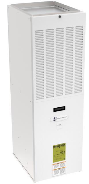
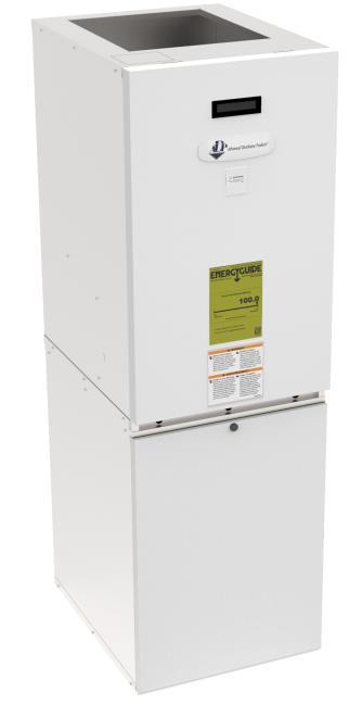
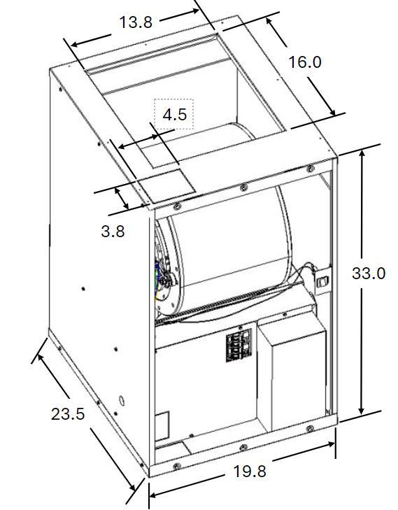
• Standard footprint for installation in manufactured homes.
• Compatible with 2-5 Ton AC or HP systems.
• Factory configured for downflow, field convertible for up-flow.
• Electric heat available factory or field installed for 208/240 V models.
• Multiple coil cabinet and filter grille options available.
• Perfectly matches with ADP manufactured housing coils.
• Meets UL 60335-2-40 product requirements.
• Blower panel with handle and push-to-lock feature for easy access.
• Cabinet and door lined with high quality 5/8" foil faced insulation for quiet operation.
• Cabinet constructed of heavy-gauge, corrosion-resistant galvanized steel.
• Slide-out blower assemblies for easy access to blower motor.
• 120 V or 208/240 V 60 Hz supply voltages available.
• 5-speed high-efficiency ECM motor.
• Terminal board with screw down connections for thermostat wiring.
• Fan time delay built-in (1 second on, 45 seconds off).
• Multiple knockout options for line voltage and thermostat connections.
• Blower door safety switch on all models.
Nominal CFM Range
[1]
Maximum Electric Heat Available (kW)
Transformer Size and Type
Blower Data
5-Speed High Efficiency ECM Motor (120 V)
Blower Data
5-Speed High Efficiency ECM
Motor (240 V)
Approx. Weight lbs (base unit w/o electric heat)
AMHE3D*
AMHE4D*
Notes :
1. All data is given while air handler is operating with a dry coil and air filter installed.
2. Speeds marked *bold with asterisk are the factory speed settings for Cooling.
3. Speeds marked #bold with asterisk are the factory speed settings for Heating.
4. Heating speeds should not be reduced below factory setting.
5. Different speeds can be set for cooling mode; see installation instructions for changing cooling speeds. AMHE5D*
Wiring Diagram
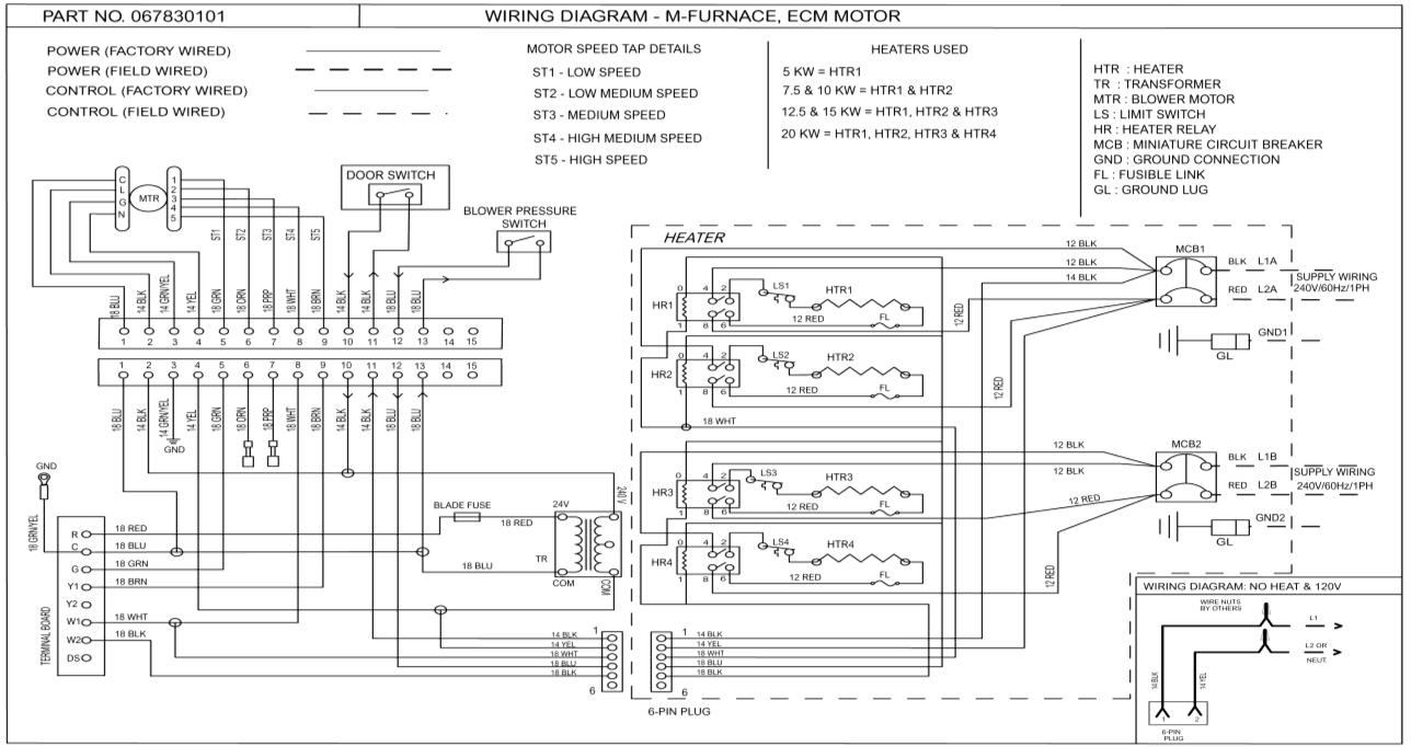
Cooling Application Only
Thermostat Terminals
Condensing unit Terminals mFurnace Terminals
Cooling with Single-Stage Electric Heat Application
Thermostat Terminals
Condensing unit Terminals mFurnace Terminals
Cooling with Two-Stage Electric Heat Application
Thermostat Terminals
unit Terminals
Terminals
Heat Pump with Single-Stage Electric Heat Application
Thermostat Terminals
Condensing unit Terminals mFurnace Terminals
Heat Pump with Two-Stage Electric Heat Application
Thermostat Terminals mFurnace Terminals
Condensing unit Terminals
Heating Application Only
Thermostat Terminals mFurnace Terminals

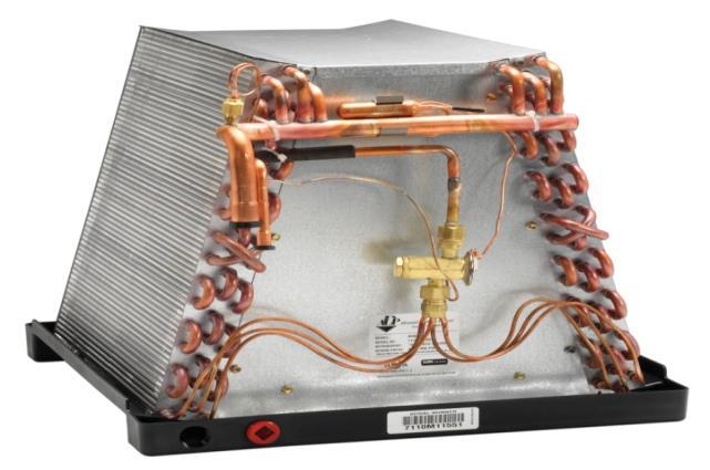
• High efficiency lanced fin design.
• “No-hassle” 5-year warranty. 10 year Limited Warranty available.
• R-32, R454B, AC & Heat Pump compatible with Refrigerant Detection System
• All coils have durable packaging with bar coded labels on the box.
• Threaded expansion valves available factory installed or as a field installed kit.
• Factory installed Refrigerant Detection Sensor Bracket
• Coils are air pressure tested at 500 psi, leak tested with helium, sealed with rubber plugs, then charged with dry air.
• Downflow drip shields are molded into drain pan.
• Filter-friendly top plate on most models (except 22" & above).
• Down-turned headers are sized out to easily receive line set.
• Factory software for TXV failure testing.
• Includes die-cut foam sheet for sealing, drain ELL, drain hose & clamp.
• Dedicated upflow/downflow.
• Copper refrigerant connections for easy brazing
• Rifled copper tubing.
• Field or factory installed threaded expansion valve.


Refrigerant Detection System (Field Configurable)
Series R = RDS Controller & Sensor (Factory Installed)
M = Manufactured Housing
L = Leak Detection Sensor (Factory Installed) (Uncased)
N = Not Included (Field Installed)
Nominal MBTUH
Slab Number
E30
E31 etc.
Refrigerant Type & Metering Device (Field Configurable)
1 = Piston *
A = R-454B Non-bleed HP-A/C TXV
B = R-32 Non-bleed HP-A/C TXV
C = R-454B Bleed HP-A/C TXV
* R-454B Piston factory installed to match the nominal BTU rating of the coil.