PORTFOLIO

GULSHAN KISHORE INTERIOR ARCHITECT AND DESIGNER

The task of the project was to design a residential space for a family by using only 3 shipping containers while offering as many amenities as possible.
Spatial understanding played a key role in providing the best possible outcome of the massing.

To utilize the space more efficiently, the containers are arranged around a staircase where the second container is also the landing of the staircase which also connects and ends at the third container.
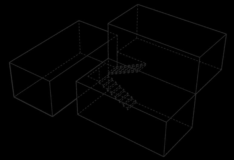
This approach also created enough height difference between the first and the third container, so that the top of the first container can also be used as a rooftop space through the third one.

The slope of the site has also been taken into consideration while designing to minimize the amount of required excavation and to provide a better panoramic view of the building.
Designing this container house reminded me of Legos where small identical blocks come together to build something interesting.
First container: Common space and kitchen with the only entrance of the house.
Second container: Connected and also functioning as the transition space and the landing of the staircase. It has a master bedroom with a bay window and a bathroom which can also be used from the first container through stairs.
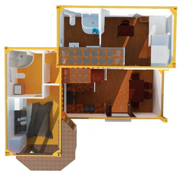
Third container: The last container where the staircase is ending and furnishes the children’s room with an attached bathroom.
Here, the first container also provides an accessible roof-top for this one which offers an elevated panoramic view.
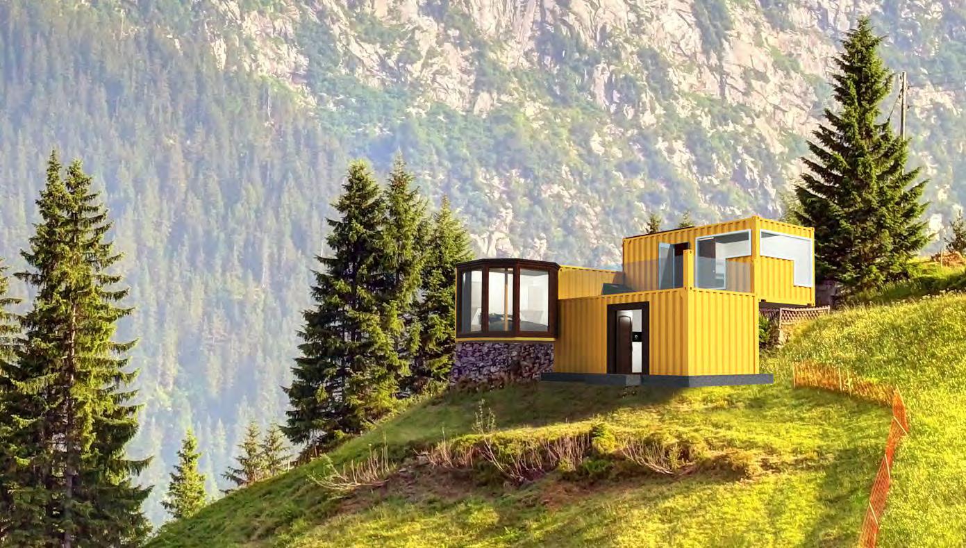 Fig: 1.3
3-D top view (Sketchup and V-ray )
Fig: 1.4
3-D view of the house (Sketchup, V-ray, and Photoshop)
Fig: 1.3
3-D top view (Sketchup and V-ray )
Fig: 1.4
3-D view of the house (Sketchup, V-ray, and Photoshop)
This Daycare is stretched over 2 floors offering all the facilities children could ever need in a daycare including learning, playing, eating, and sleeping areas.
Children have a very different set of requirements, not just in terms of facilities but also in terms of anthropometrics.
In this project, several critical decisions have been after analyzing the space from the children’s perspective and understanding their requirements.
One of the main focuses behind this design solution is to provide better connectivity on both floors for the children.
Instead of using traditional staircases or elevators, the project offers something unique that makes this task more like a fun activity for them.
Keeping that in mind, the central spaces of both the floors have been linked together to create amusing vertical connectivity for the children which is less like a staircase and more like a playing structure.
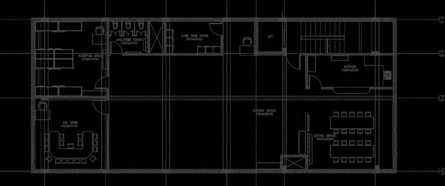
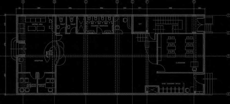 Fig: 2.1
Ground floor plan ( AutoCAD)
Fig: 2.2
First floor plan ( AutoCAD)
Fig: 2.1
Ground floor plan ( AutoCAD)
Fig: 2.2
First floor plan ( AutoCAD)
This customized rendered view below demonstrates the idea of connectivity of both floors.
There are a few steps followed by a small ramp and a diagonal climbing slope designed to provide a steady path of activities without any obstacles and going back to the ground floor is just a slide away. This will also help children to be more active and interactive.
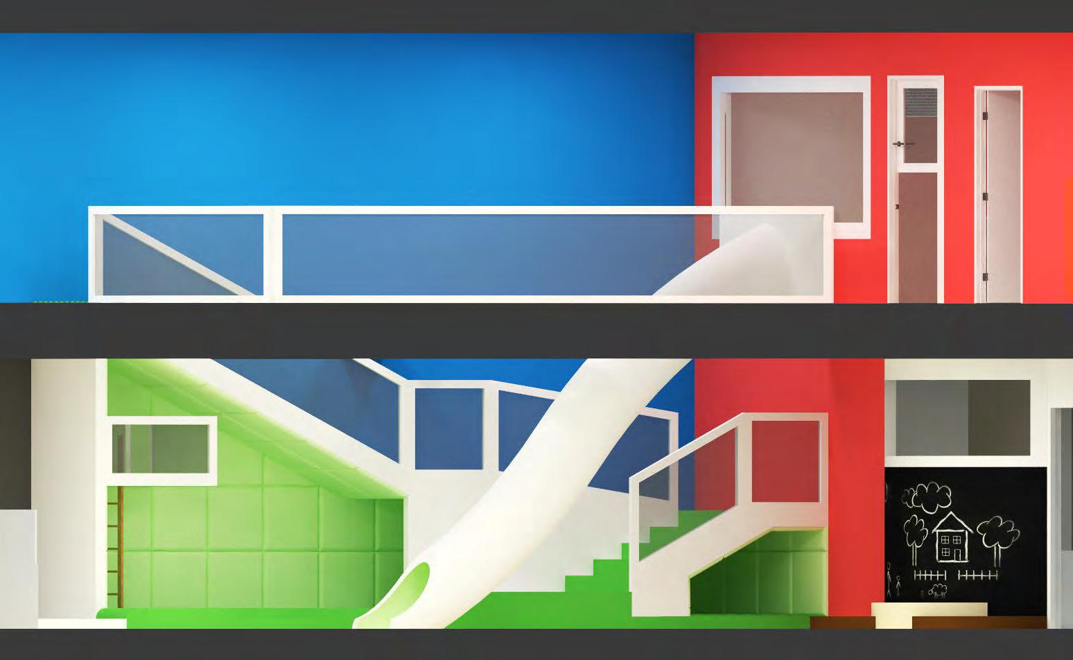 Fig: 2.3
Orthographic rendered view (Sketchup and V-ray )
Fig: 2.3
Orthographic rendered view (Sketchup and V-ray )
In simple words, a Blockchain is a chain of blocks where each block contains information about cryptocurrency of a user. Blocks are linked with each other and share information to ensure smooth and secure transactions.
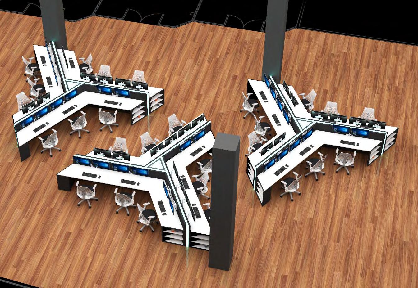
While maintaining the aesthetic of a premium office space, this design offers an exceptional casual working layout perfectly suitable for such a working environment.
In this layout, each island of the workstation portrays a connection between the user and the block at the center; creating an intellectual bond between the employees and their work.
This layout also eliminates the typical “open-plan” layouts of office space and provides a more interconnected approach to the arrangement while establishing a bond with the nature of their work.
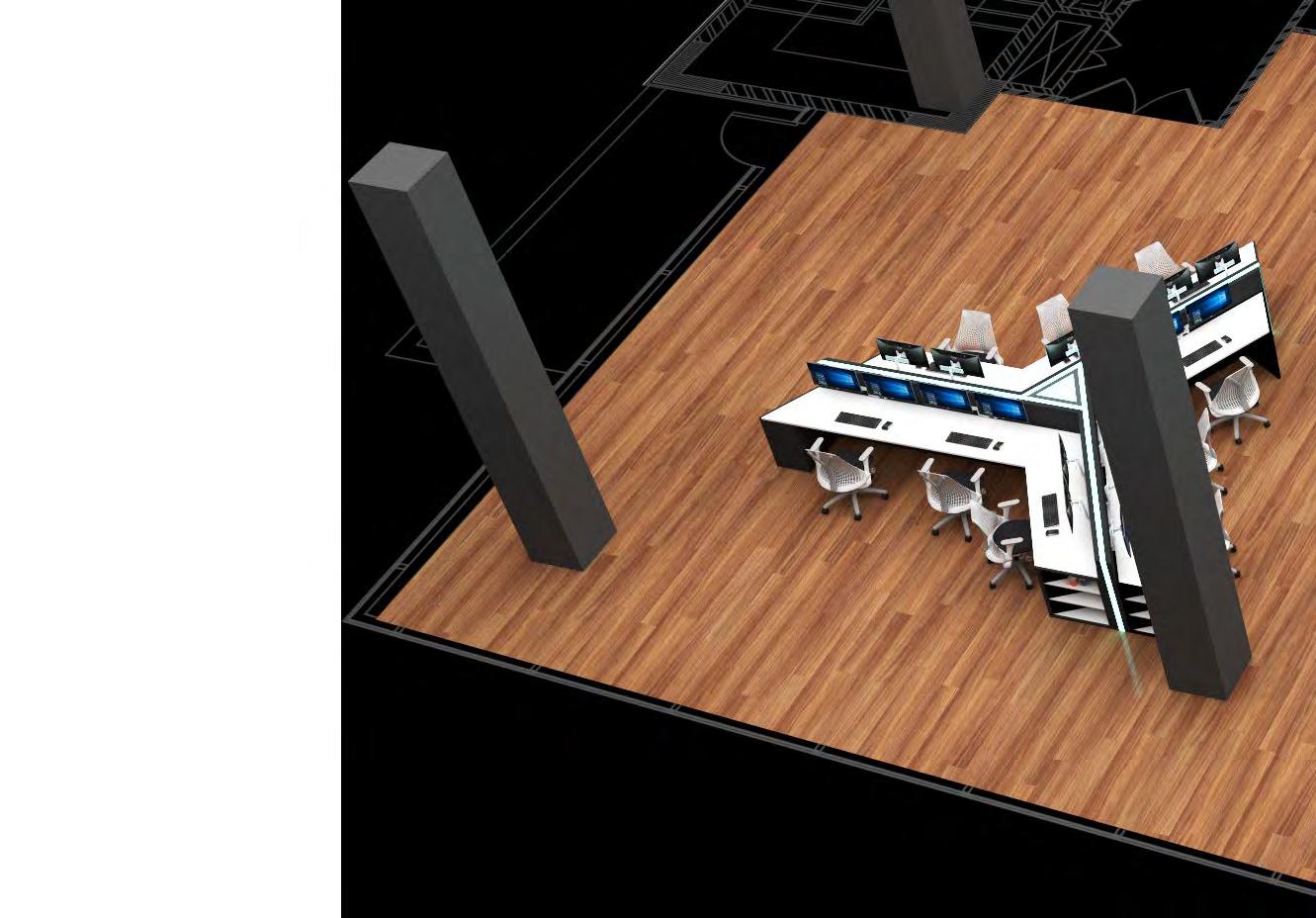 Fig: 3.1
Workstation layout (Revit and Enscape)
Fig: 3.1
Workstation layout (Revit and Enscape)

 Hardwood Flooring
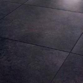
Rubber Flooring Sheet
White Corian
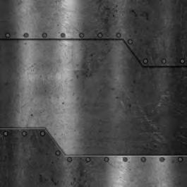
Metal Finish Cladding
Fig: 3.2
Workstation area (Revit and Enscape)
Hardwood Flooring
Rubber Flooring Sheet
White Corian
Metal Finish Cladding
Fig: 3.2
Workstation area (Revit and Enscape)
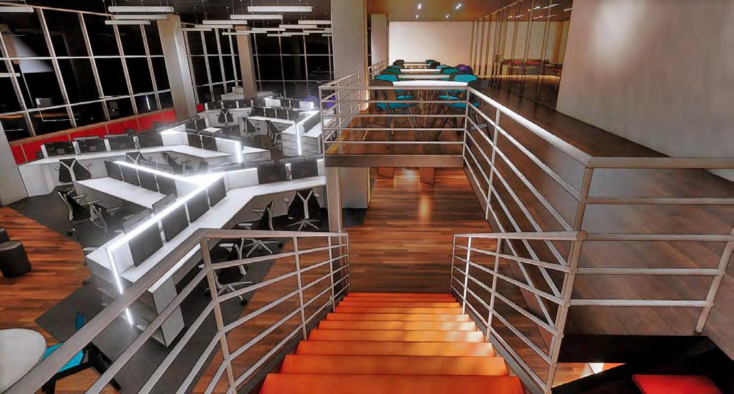
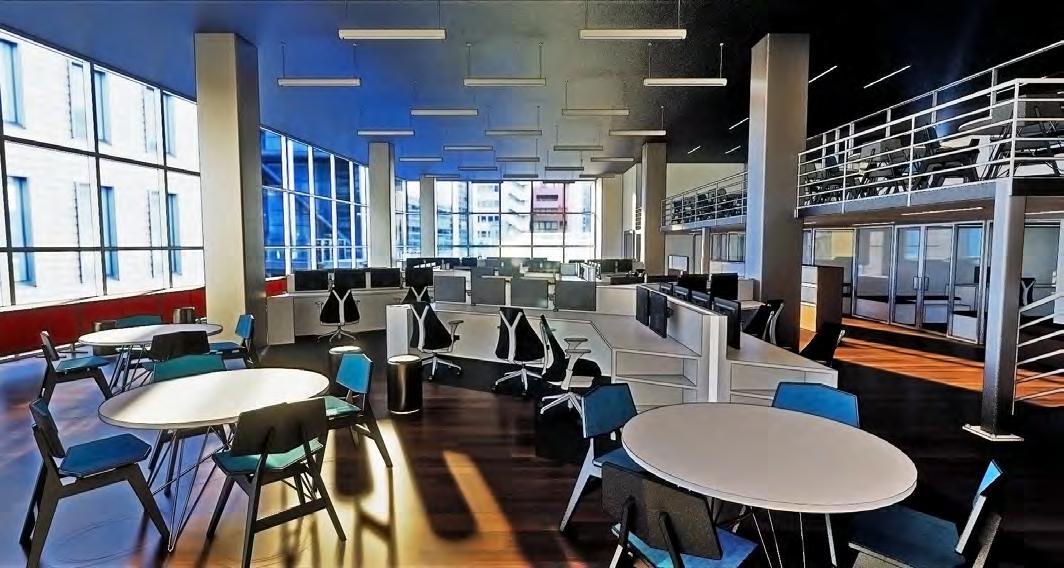
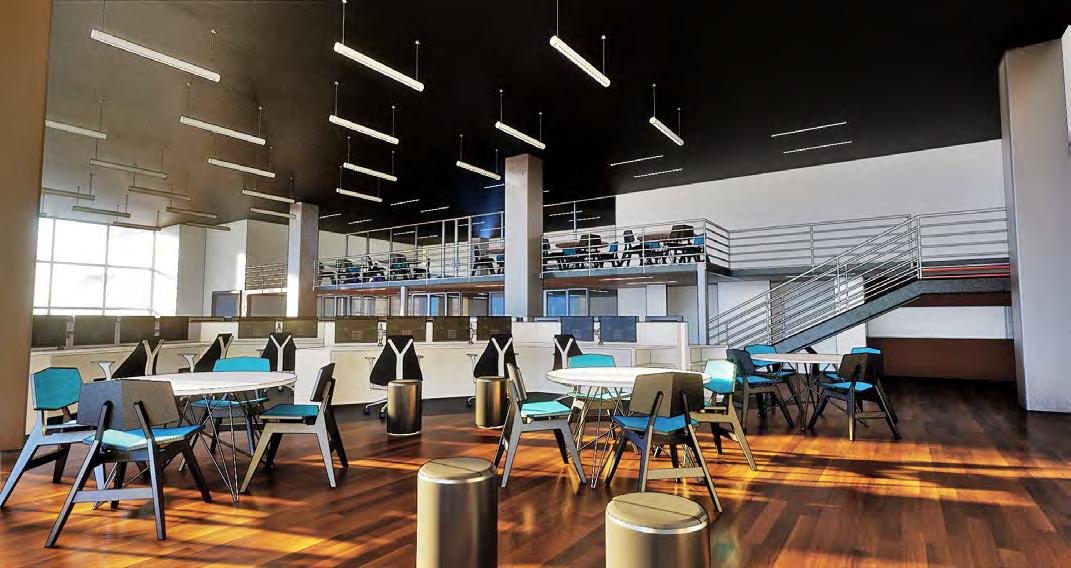 Fig: 3.3
Workstation area (Revit and Enscape)
Fig: 3.4
Mezzanine area (night) (Revit and Enscape)
Fig: 3.3
Workstation area (Revit and Enscape)
Fig: 3.4
Mezzanine area (night) (Revit and Enscape)
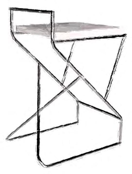
People often define minimalism by simplicity. Maybe because most of the things categorized as minimalistic are very simple and basic in appearance. But a minimalistic design doesn’t have to be simple.
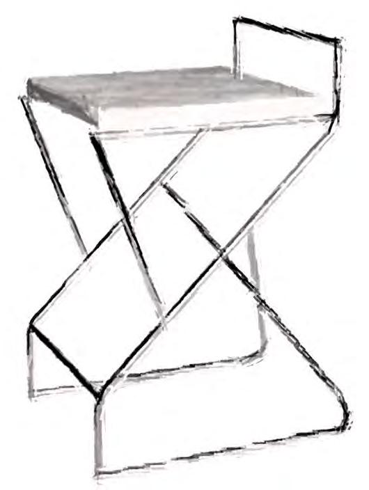
To demonstrate this idea, I designed this chair which is intricate in design and minimalistic in appearance. Inspired by a basic metal rack and aspire to step into a sophisticated interior space.
This design holds a complex connection of the metal elements which is crowned by a white stable and uniform geometric figure. Here each metal part plays an important role in maintaining the structural integrity of this chair, making everything seem simple and necessary while still holding a complex design.
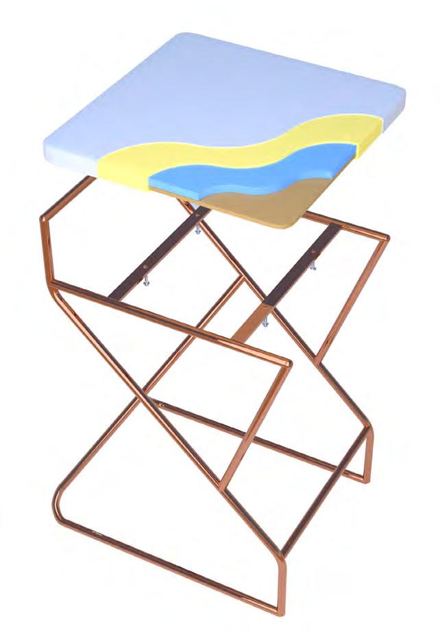


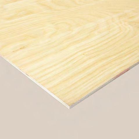 Plywood Sheet
Hard Chip-Foam
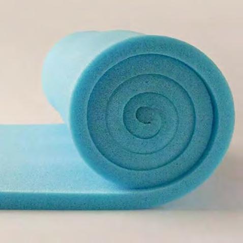
Soft Foam
Faux Leather
Fig: 4.3 Chair (exploded view) (3DS Max and V-ray )
Plywood Sheet
Hard Chip-Foam
Soft Foam
Faux Leather
Fig: 4.3 Chair (exploded view) (3DS Max and V-ray )
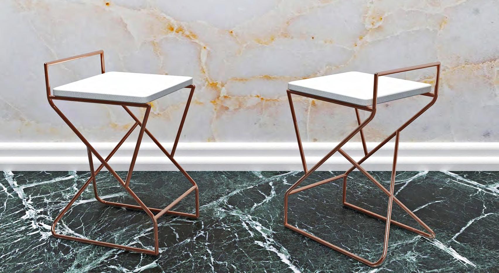 Fig: 4.4
Rendered view (3DS Max and V-ray )
Fig: 4.4
Rendered view (3DS Max and V-ray )
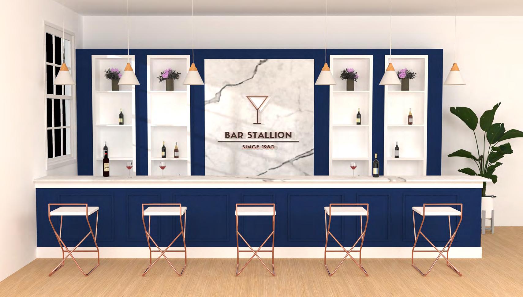 Fig: 4.5
Rendered view (3DS Max and V-ray )
Fig: 4.5
Rendered view (3DS Max and V-ray )
A place where people can learn ways to improve their health and lifestyle. The project is focused on avoiding and improving the health condition in the most natural way possible.
The project consists of three major spaces, which are cooking space, gardening space, and exercise space.
The image on the right demonstrates the changes in massing. Spaces have been altered and merged into one another to improve connectivity and functionality to prevent users from feeling separated by the space and allowing them to experience one space while being in another.
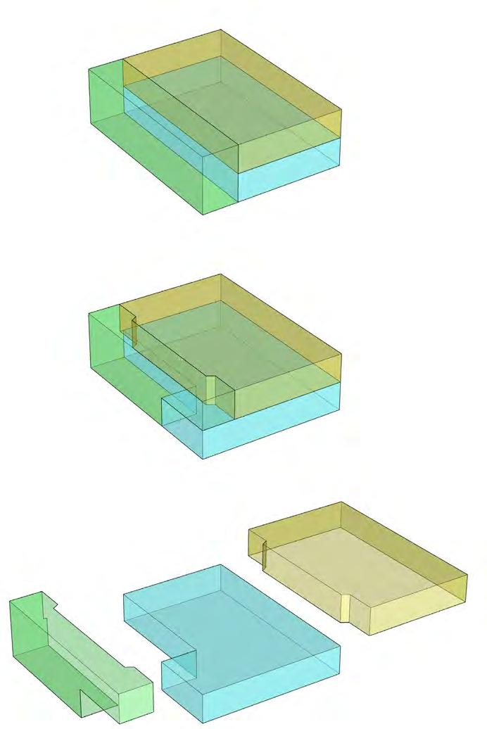
Different colors, materials, and levels have been used in these spaces to make them identical while still keeping them together as a whole.
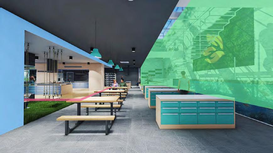 Fig: 5.1
Common area (rendered view) (Sketchup and Lumion)
Fig: 5.2
Massing diagram (Sketchup and V-ray )
Fig: 5.1
Common area (rendered view) (Sketchup and Lumion)
Fig: 5.2
Massing diagram (Sketchup and V-ray )
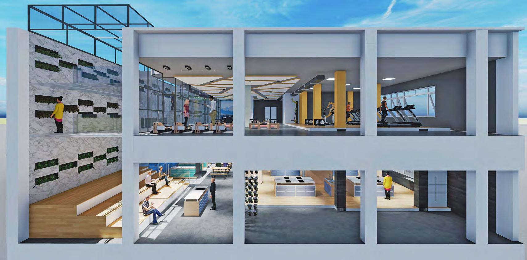 Fig: 5.3
Sectional Perspective (rendered view) (Sketchup and Lumion)
Fig: 5.3
Sectional Perspective (rendered view) (Sketchup and Lumion)
Elevated seating space for orientation discussion, cooking lessons, and gardening instructions and connected with cooking space and gardening space. Groups will be made based on their biometric data and will be trained together throughout the course.
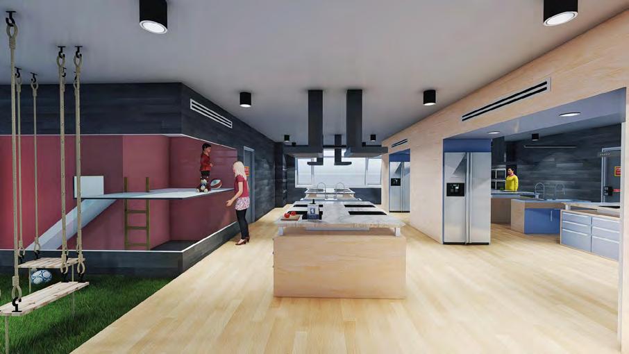
Four counters, each equipped with four cooking spaces; also ideal for group cooking classes. The purpose of this area is to teach people how to make a variety of healthy and organic meals which they can incorporate into their daily diet. Here they will also understand the value of organic food and learn how easy and affordable it is to get it.
Having an over-priced organic meal at a restaurant is not a solution for this. One has to incorporate such a diet in their daily lifestyle as this place follows the saying “give a man a fish and you will feed him for a day, teach a man to fish and you feed him for a lifetime ”-Anne Isabella.
Parents can also cook freely by leaving their kids in the playing area which is connected with this area so that they can always keep an eye on them.
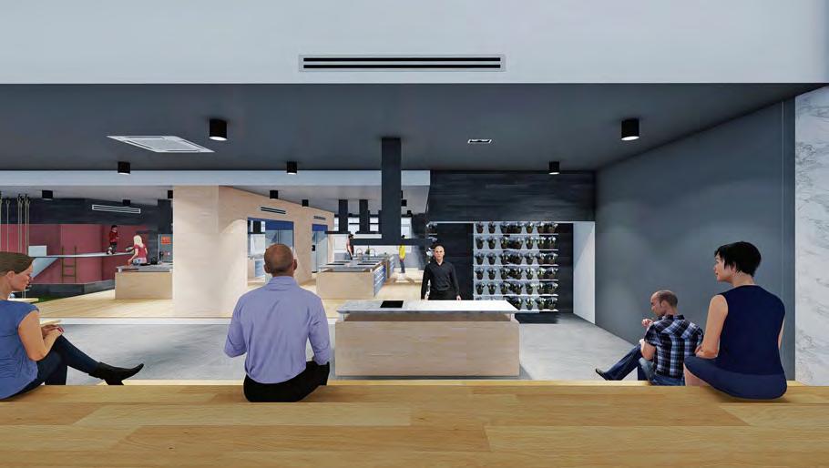 Fig: 5.4
Discussion area (rendered view) (Sketchup and Lumion)
Fig: 5.5
Cooking area (rendered view) (Sketchup and Lumion)
Fig: 5.4
Discussion area (rendered view) (Sketchup and Lumion)
Fig: 5.5
Cooking area (rendered view) (Sketchup and Lumion)
This place uses an Aquaponic system to achieve indoor organic gardening. Since this system is water-based instead of soil, the gardening process will be tidier. The water supply is connected with the fish aquarium in which ammonia from fish waste is converted into nitrite which is the main nutrition source for the plants.
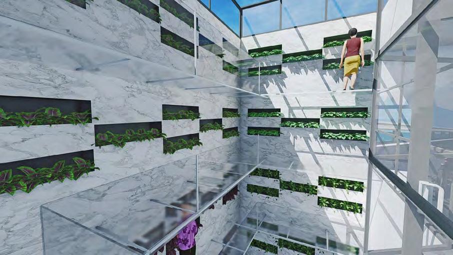
The aquarium is located in the central space on the first floor, and knowing the fact that this system is run by the fishes gives a wholesome feeling of connectivity with nature.
With proper training, people can grow most of the vegetables and herbs in this system and can also create a small Aquaponic system at their home for their loved ones.
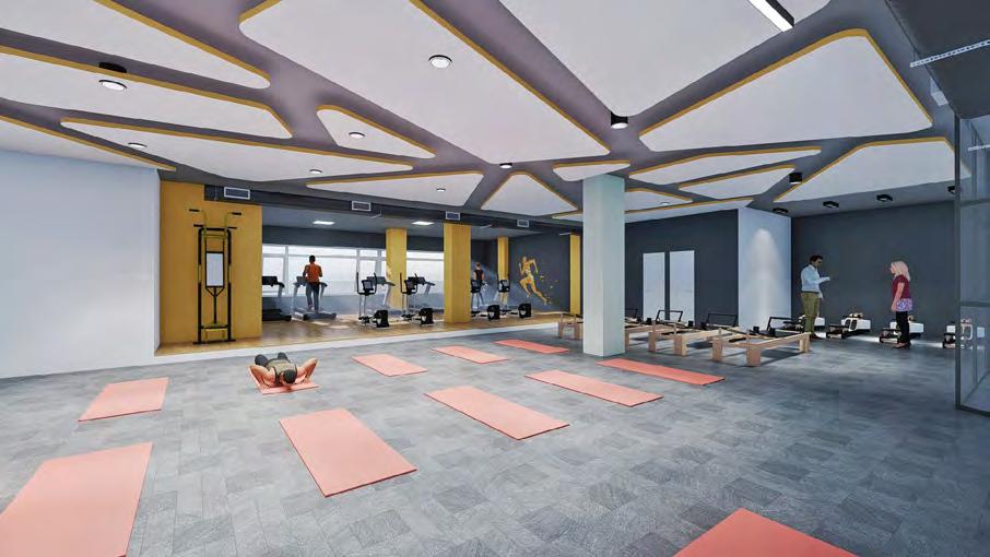
This area focuses mainly upon endurance exercises, which helps in keeping the body healthy and active.
The same groups can also be carried forward for exercises. So that they can grow food, cook, and exercise together for a better result.
People usually can not achieve and maintain a healthy lifestyle because all these things are necessary for that. Here in this project, all these functions are interconnected with each other to give the best possible result.
This would be a single destination for one seeking a healthy lifestyle.
Fig: 5.6 Gardening area (rendered view) (Sketchup and Lumion) Fig: 5.7 Exercise area (rendered view) (Sketchup and Lumion) Fig: 5.8 First floor plan ( AutoCAD) Fig: 5.9 Second floor plan ( AutoCAD)
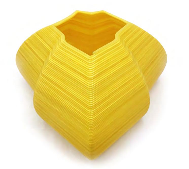
I used Grasshopper and Python to generate objects that were defined by the relative motion of two or more spheres. I started by creating a list of spherical coordinates and using that list as a reference to calculate new coordinates. Each item (coordinate) in the list goes through a series of calculations, creating a whole new list of coordinates. Soon after that, I realized that we can create anything we want. We can create something which we already know and also something which we never thought of.
We as designers usually use visual-based programs to design anything on a computer like Rhino3D. It is a good way to make something that we have thought of or something that we already have an image of. But by using textbased computational designing, we can also achieve something that no one has imagined before.
If we were to draw an object using the same process of calculations and coordinates plotting, it would take days if not weeks just to draw one single object.
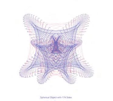
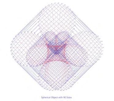
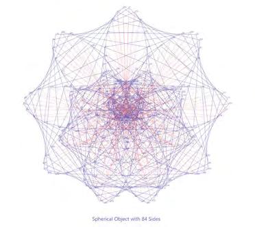
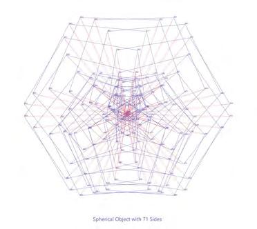
These programs can generate it in just a click. There are so many parameters that I can change in this data stream which will give me infinite possibilities.
Even these raw generated forms can give us a lot of new ideas for brainstorming. This video shows how my data stream is generating images of different objects.
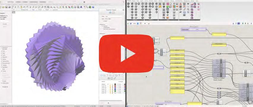
To understand the relationship between the Grasshopper data stream and the arm of the KUKA Robot, I started changing the data as per the movement I want from the KUKA arm. It was very fascinating to see how precise control I had of that powerful robotic arm.
I modified the data stream and created a list of coordinates for that arm to move from one point to another. I had a few constraints like the print had to be continuous and self-supporting, but I solved those problems by precisely defining the path, controlling the overlapping of each layer, and speed of the print.
After having a successful result, I went ahead and made further modifications in each list of the tree. I wanted to see how complex object I can make but still having a successful print.
The timelapse video on the right shows the whole printing process. It took around 4 hours for that print to complete.
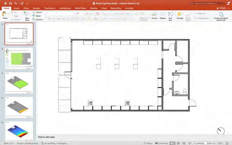
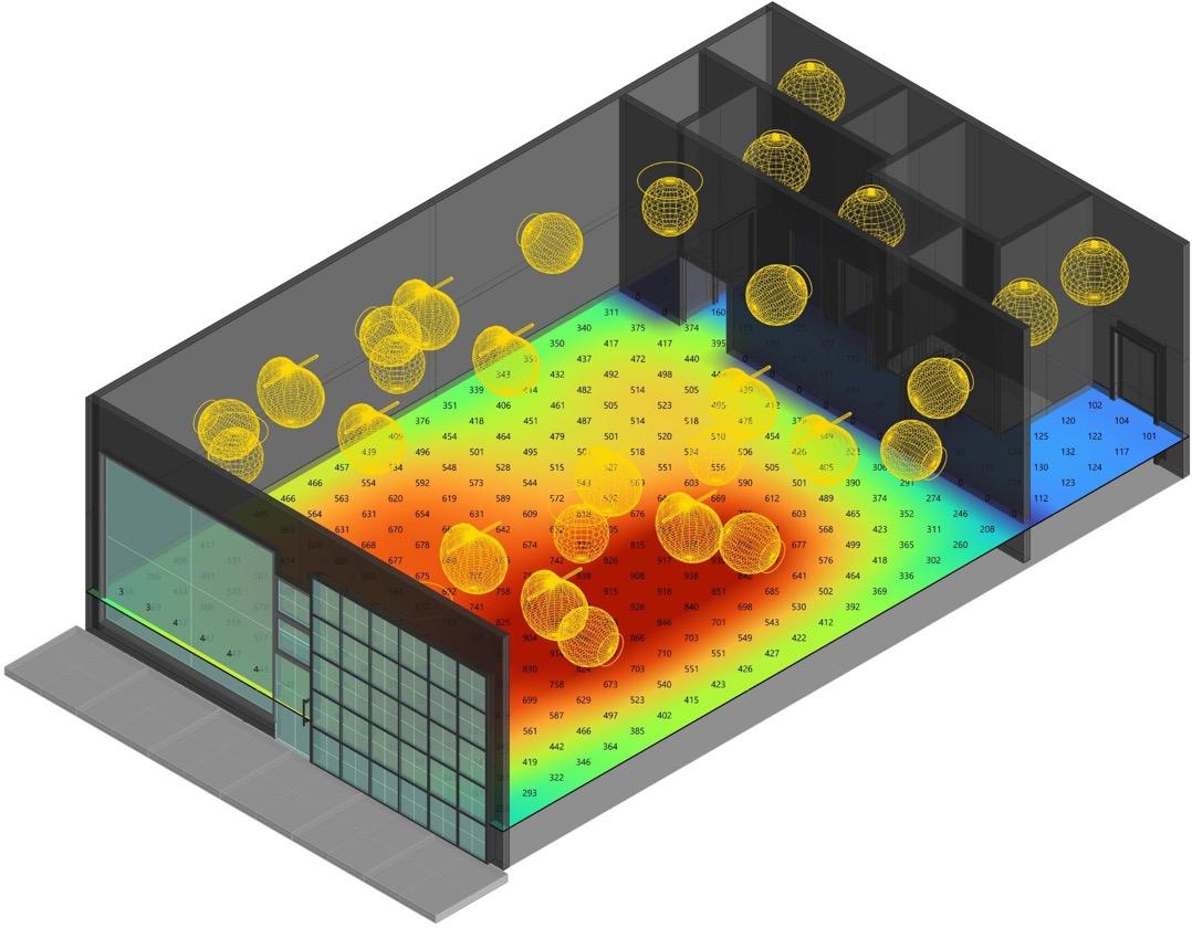
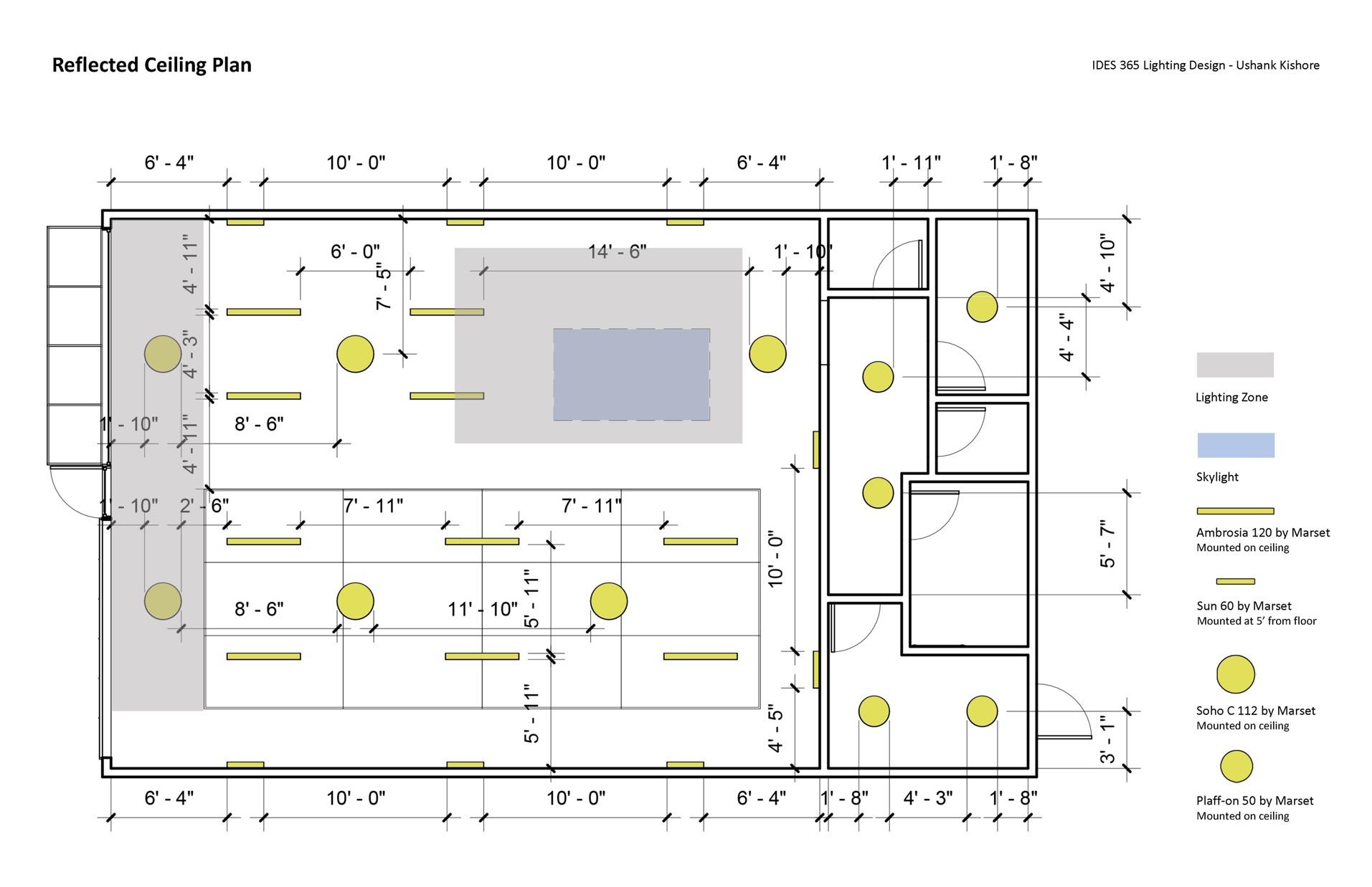
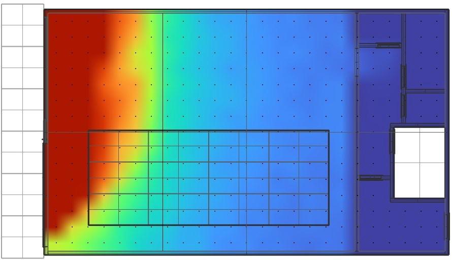
Lighting designing is a well-planned and calculated method of providing a lighting solution for a project. Daylight is beneficial for almost every project but it is very important to control it to avoid excess illumination, glares, and heat.
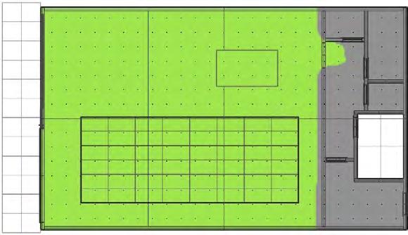
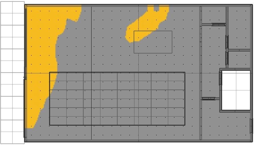
In this retail project, I used Rhino 3D and ClimateStudio programs to generate the daylight simulation and collect important data to identify the potential issues related to lighting and solve them by strategically placing the skylight and selecting the right lighting fixtures accordingly.
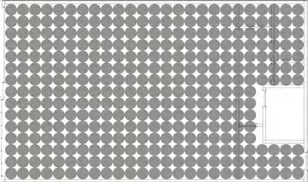
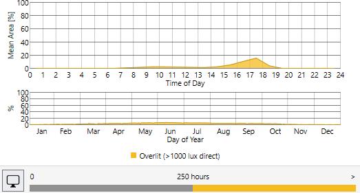
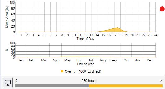
Sensors are placed 24” apart and data like Spatial daylight, Sunlight exposure, and average LUX are collected before and after placing the skylight. The area of the skylight has been adjusted to get the desired results.
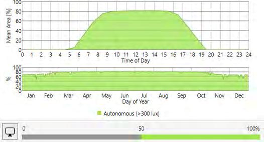
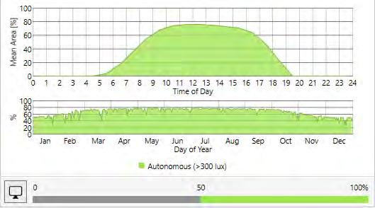
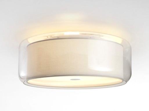
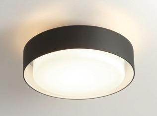
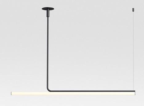
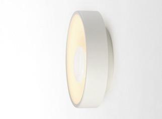
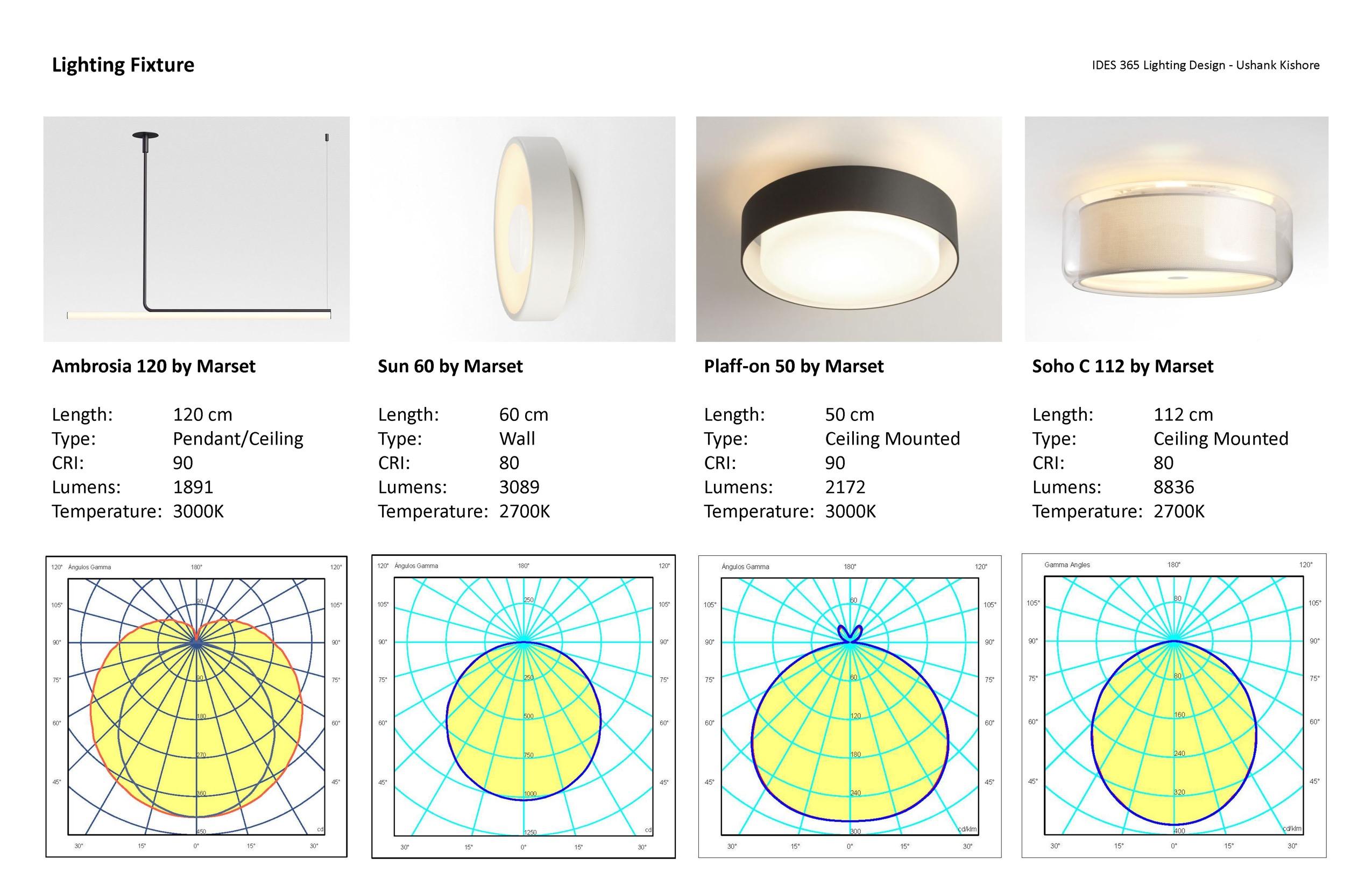
Lighting fixtures were selected as per the specifications and their placements were also finalized after achieving suitable LUX levels by using their IES data files and Polar maps in the project model.
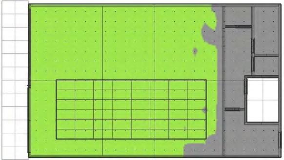
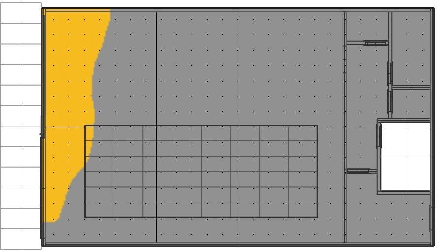
The annual exposure has also increased from 10.7% to 15.2%
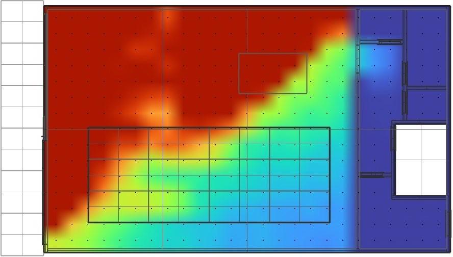
Average LUX levels
Avg. LUX levels have drastically increased from 1137 to 2266 and now meet the LUX requirements from 8 a.m. to 1 p.m.
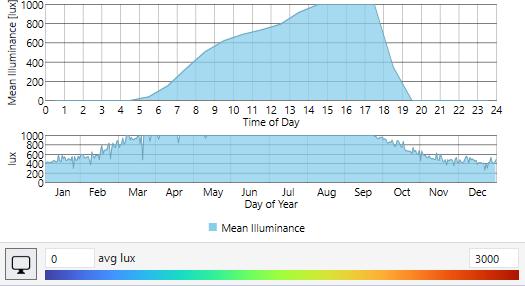
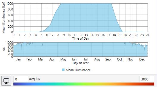 *Daylight turned off, LUX from luminaires only.
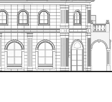
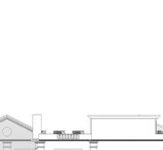
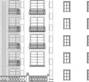
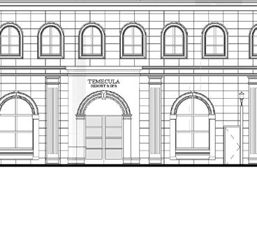
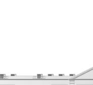
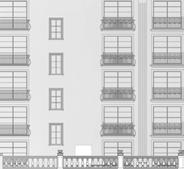
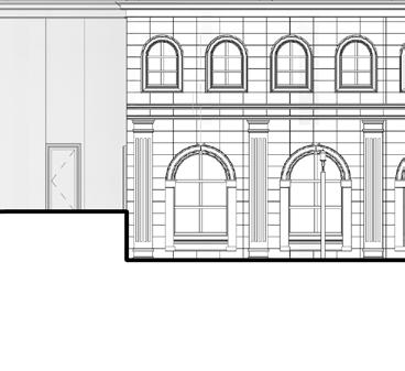
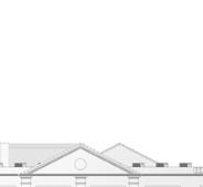
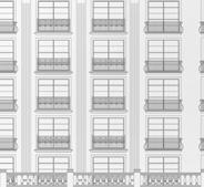
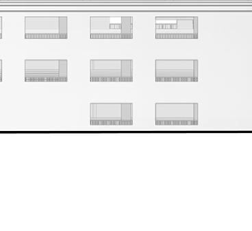
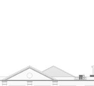
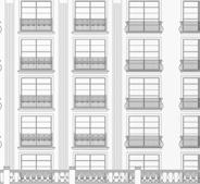
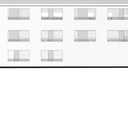
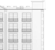
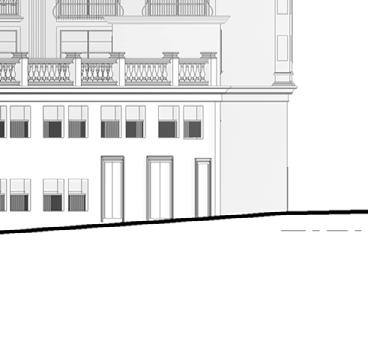
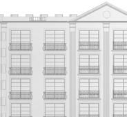
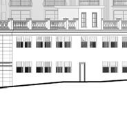
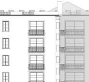
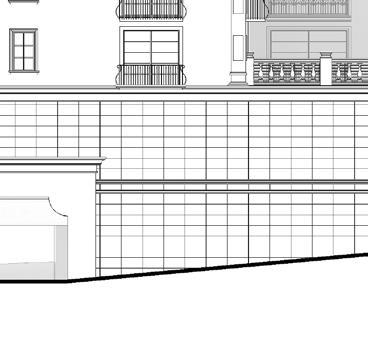
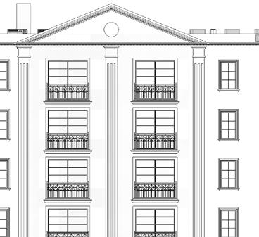
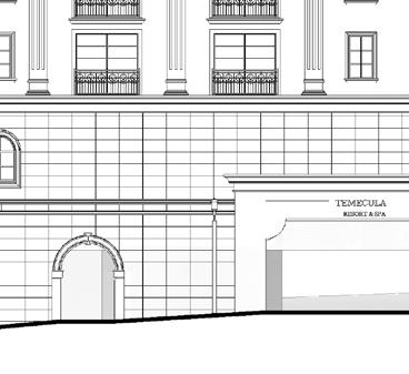
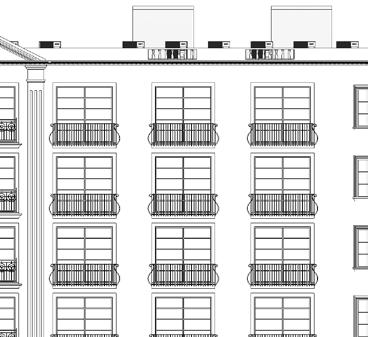
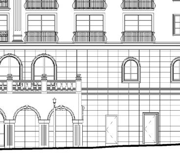
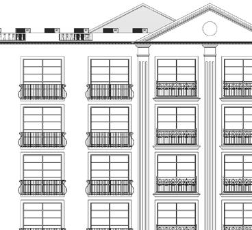
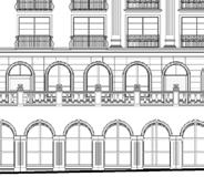
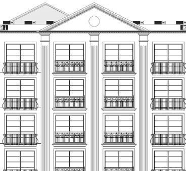
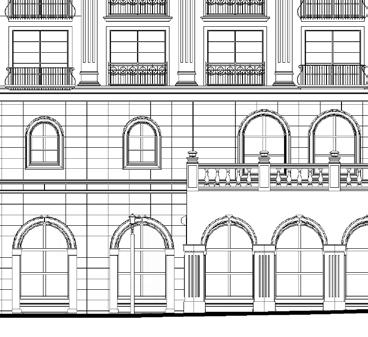
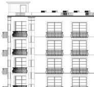
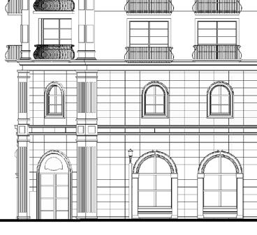
In this hospitality project, my team and I were responsible for generating the submittal set for approval and making the required changes per the feedback.


Some of my tasks were to design the layout and accommodate as many suites as possible on each floor, planning parking spaces, cafes, and egresses.
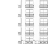
In this project, I spent most of my time on Revit working on floor plans and elevations and completing all the required tasks to get the submittal set approved.
I was also responsible to make sure that the project is following all the city guidelines and restrictions like setbacks, dimensions of openings on facade, and color selections.