
Architectural Design Studio 4
JOURNAL
Semester 1 2024

PART C - Form Finding to Water-Front Place-Making
Part C1 - Project Summary
Part C2 - Precedent Study
Part C3 - Revised Design Vision and Analysis
Part C4 - Design Iterations
Part C5 - Before and After Master-Plan
Part C6 - Facade Design Iterations and Ideations
PART D - Detailed Design and Tectonics
Part D1 - Diagram Drawings
Part D2 - Mixed
Part D3 - Ferry Station Final Drawings
Part D4 - Final Student Accommdation Drawings
Part D6 - Facade Detail Drawings
Part D6 - Final before and after master-plan
Part D7 - Renders and Key Moments
Part D8 -
Part D9 - Refernces
About Me
GOCE LAZARESKI Introduction

Ph: (+61) 0470 175 182 (AU)
Email: gocelazareski88@gmail�com
Address: 14 Reservoir Crescent Rowville
My name is Goce Lazareski, I am a local student from Melbourne in my third year studying architecture at Swinburne University�
While I have professional experience however i do work on projects with my dad and his architect from time to time in relation to documentation� I am intrigued by the way spaces are created and crafted early on in the design process and how it develops into beautiful building people will enjoy for a long time
In terms of working in a group my preference is to work in groups as it allows me to gain inspiration while work positively and collaboratively as a team�
Some of the skills i would like to improve on include cleaning up my presentation ensuring that it is to a professional standard, meeting all requirements of the brief�
Skills: Revit Indesign
Rhino Acrobat Apps
Enscape� Autocad
Twinmotion Illustrator
Sketchup
A Project from a previous studio outcome involved a site on Walsh Street in South Yarra which i was tasked with providing a response to the issue of increased density by integrating as many dwellings as we could on the site so that future residents that arrived from overseas or interstate were in close proximity to the CBD and other major locations whilst incorporating design elements from highly respected Australian architect Robin Boyd�
I chose this particular project from design studio 3 because it showcased my passion for wanting to push the boundaries of how many dwellings can be constructed on a particular site n matter the constraints whilst creating respectful designs that pay homage to the neighborhood character and street scape�

Figure 01 ( Past work from Design Studio 3 Created by Goce Lazareski)
PART A - FORM FINDING AND CONCEPTUAL FRAMEWORK
Introduction and Background Research on Form Finding
Week 1-6
PART A - Form Finding and Conceptual Framework
Provide a brief history of form-finding techniques in architecture.
The history of form-finding techniques in architecture can be traced back to the beginning of the 20th century before the digital revolution began� Throughout this period several architects including Frei Otto and Fredrick Kiesler began to take a different design approach to provide a method that seemed impossible yet realistic to prove while at the same time having to be linked to the current trends in computation� However, the early 1980s and 1990s proved to be a turning point as the techniques American Architect Peter Eisenmann became the first to use the techniques as part of his design approach to contemporary design which is most notable in his projects which include the Bio centrum in Frankfurt�
Discuss the role of form finding in architecture.
The role of form finding in architecture can be best described as the investigation of different processes using various different shapes or building structures and nature in order to discover/enhance ways in which to organize buildings for inhabitants that are going to use them whether it’s for work, shopping or living furthermore it also it can also help improve the functionality, aesthetic, appeal and overall impact on the environment furthermore other building performances that have to be considered and taken into account include such structural, acoustic and functional requirements as a result of analyzed processes that are investigated� Notable examples include the NYC World Trade Centre Transportation Hub in the US designed by renewed Architect Santiago Calatrava and the Seattle Central Library located designed by OMA + LMN
PART A - Form Finding and Conceptual Framework

Figure 04: NYC WORLD TRADE CENTER TRANSPORTATION HUB (THE OCULUS)
Pires, S� (2021, May 10)� 10 gravity-defying structures by Santiago Calatrava, legendary architect and Engineer� My Modern Met� https://mymodernmet com/santiago-calatrava-buildings/

Figure 06 Seattle Central Library
Pires, S� (2021, May 10)� 10 gravity-defying structures by Santiago Calatrava, legendary architect and Engineer� My Modern Met� https://mymodernmet com/santiago-calatrava-buildings/

Figure 05 Example of Form finding in Architecture Hnin, T. (2023, December 15). An introductory guide to form-finding in Architecture (2024). Novatr Prev OX. https://www.novatr.com/blog/form-finding-in-architecture

Figure 07
Hnin, T. (2023, December 15). An introductory guide to form-finding in Architecture (2024). Novatr Prev OX. https://www.novatr.com/blog/form-finding-in-architecture
PART A - Form Finding and Conceptual Framework
A0 Introduction:
Case study 1 - World Trade Centre Transporation Hub
Year: 2003-2016
Location: New York City United States
Team: Santiago Calatrava
Status: Completed
The works of Santiago Calatrava are a perfect example of how form finding can be inspired by nature and living organisms that are able to reflect the context, social structure and technological feats that are exemplified through computational design tools furthermore this is evident in Calatrava’s project in NYC world trade center transportation hub) an below ground train-station that replaced the Port Authority’s Trans Hudson Path rail system providing a seamless indoor pedestrian access whilst creating a inspiring light filled gathering place.
Its architecture consists of a free standing structure with rafters that spring from two 350 ft arches flanking the project’s central axis� Between the arches, a 330 ft operable skylight frames a slice of the New York sky and opens on temperate days, the form can be summed up as been the image of a bird been released from a child’s hand� The main materials of the structure comprise of steel ribs that extend to create two canopies over the northern and southern potions of the plaza, glass combined with the steel ribs are arrayed in a large elliptical shape�

Pires, S� (2021, May 10)� 10 gravity-defying structures by Santiago Calatrava, legendary architect and Engineer� My Modern Met� https:// mymodernmet�com/santiago-calatrava-buildings/
Figure 08: NYC WORLD TRADE CENTER TRANSPORTATION HUB (THE OCULUS)
PART A - Form Finding and Conceptual Framework
Case study 2 - Thallus Installation by Zaha
Year: 2017
Location: Pinacoteca di Brera Milan Italy
Team: Zaha Hadid
Status: Completed
The Thallus installation located in the city of Milan, named after the Greek word for Flora, the installation serves as an experimental prototype that seeks to investigate form and pattern that are generated through advanced manufacturing and computational methods�
The installation is created by automated additive manufacture including hot wire cutting technology, furthermore the structure represents/signals an ongoing investigation and research into robotic assisted design undertaken by Zaha Hadid’s Computational division� The experiment has unlocked the potentials of what can be achieved through mechanisms and customization while further advancing the ACE (architecture, construction, engineering) industries�

09: Thallus Installation
Zaha Hadid architects� Thallus Installation –Zaha Hadid Architects� (n�d�)� https://www�zahahadid com/design/thallus-installation/

Zaha Hadid architects� Thallus Installation – Zaha Hadid Architects (n d ) https://www zaha-hadid com/design/ thallus-installation/
Figure
Figure 10: Thallus Installation
Hadid
Part A1 - From Concept to Creation
Week 1-2
PART A - Form Finding and Conceptual Framework
What is a Tensile Structure?
Tensile structures are structural elements that require only tension and no compression or bending to maintain their shape and stability� However, can be characterized by flexible fabric membranes which are supported by cables, structural steel framework and foundations� They are often integrated into architecture and engineering to create large open spaces with minimal structural support from columns and beams� Examples of tonsil structures in architecture include various forms including canopies, roofs, and facades�
The tensile structures are designed to distribute forces evenly across multiple surfaces resulting in minimal bending movements and structural stress thus allowing it to be efficient in using less materials which can lead to interesting architectural designs� In relation to material usage the structures require less materials such as fabric, steel cables, form work and foundations thus allowing the durability, strength, and flexibility to remain stable for many years.
Examples of different projects that have used a Tensile Structure
- Myer Music Bowl Located in Melbourne
- Echo Orbit in Brisbane
- Inglis Play Playground in Sydney
- Elizabeth Quay Footbridge in Sydney
PART A - Form Finding and Conceptual Framework
A1�01 Introduction to Form Finding Technique 1


How tensile structures are revolutionizing the architecture industry? (n d ) https://parametricarchitecture�com/how-tensile-structures-arerevolutionizing-the-architecture-industry/
How tensile structures are revolutionizing the architecture industry? (n d ) https://parametricarchitecture�com/how-tensile-structures-arerevolutionizing-the-architecture-industry/


How tensile structures are revolutionizing the architecture industry? (n�d�)� https://parametricarchitecture�com/how-tensile-structures-arerevolutionizing-the-architecture-industry/
How tensile structures are revolutionizing the architecture industry? (n�d�)� https://parametricarchitecture�com/how-tensile-structures-arerevolutionizing-the-architecture-industry/

How tensile structures are revolutionizing the architecture industry? (n�d�)� https://parametricarchitecture com/how-tensile-structures-arerevolutionizing-the-architecture-industry/
Figure 11 Dadong Art Center by Cie + MAYU architect
Figure 12 Underwood Pavilion by Ball State University
Figure 13 The Millennium Dome by Richard Rogers
Figure 14 Olympia Park Munich Germany
Photo by Mariano Mantel
Figure 15 The mercedes Benz Stadium in Atlanta Georgia
Photo by Buro Happoid
PART A - Form Finding and Conceptual Framework
INTRODUCTION
Summary:
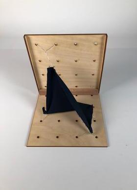
My chosen for form finding is the tensile structure technique which works by placing anchor points at various intervals around the box which can then be used by the fabric to form various geometries, the main part of the machine is a piece of stretched fabric where at each corner a piece of wire or string is attached which can then be used to create and manipulate the piece of fabric that Is anchored at various heights�
Key Principles:
The key principles that define the technique are the various variables such as changing the type of fabric that can be used such as stretchy material, anchor point positioning which can change from been an open cubed, or closed cubed, experimenting with various material systems such as spandex, strings, weights, and rubber bands,
PART A - Form Finding and Conceptual Framework
Step 1:
Construct a machine box roughly at 250 x 250 x 250 in size�
Step 2:
Drill holes at a size of 2,3 or 4mm diameter with the holes to be flexible in placing and anchoring the string and fabric�

Figure 16 Electric Drill Cordless Drill� Hire Pro� (2024, January 12) https://hireproonline com au/product/ cordless-drill/

Figure 19 Acrylic Material Clear acrylic sheet: Perspex sydney� KF Plastics� (2024, February 5)� https://www�kfplastics�com� au/plastic-sheets/clear-acrylic-sheet
Step 3:
Cut piece of stretchy fabric roughly 160mm x 160mm in size designed to fit on the bottom of the box to be to create a spatial design with only suspended elements�

Step 4:
Experiment with Different Materials
Step 5:
Experiment with various different systems such as spandex, strings, weights and Rubber Bands and various other fabrics such as elastane, spandex, Nylon and Mesh�
Figure 17 Stretched Fabric Superlabelstore� (2022, February 9)� Types of stretch fabric� https://superlabelstore� com/blog/types-of-stretch-fabric/

Figure 18 Example of Plywood 3MM 1/8” x 12 x 12 Baltic birch plywoodb/BB grade, package of 6 Amazon com au: Toys & Games� (n�d�)� https://www�amazon� com�au/3MM-12-Baltic-Birch-Plywood/dp/ B07CHX1GTD?th=1
PART A - Form Finding and Conceptual Framework


PART A - Form Finding and Conceptual Framework
Experiment 01: Tensile Structure
Form Finding Technique:
Material manipulation through Tension and Gravity
Parameters:
Strings – Placements at various anchor points
Fabric: Stretchy, thick, then and pull able�
Forces:
Tension, Structural adequacy, Location of anchor points
Wind and Gravity�
Why this technique?
The technique has the potential to create a unique façade option that can re used in many different areas within the structure such as a shading device or canopy�


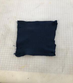


Figure_ Catalogue Of Early Forms and Iterations
Figure_ Fabric and Material used
PART A - Form Finding and Conceptual Framework
INTRODUCTION
A summary of how my technique works.
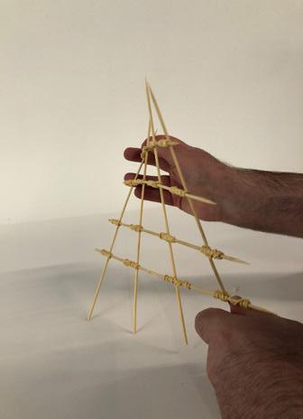
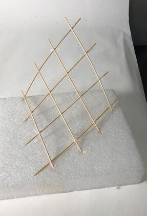
My second chosen technique is the hyperboloid also known as a ruled surface which is defined by the property that through every point in the surface, there is at least one straight line that also lies in the surface through connections using either braid Rubber bands or elastic bands that connect both the surfaces together allowing the geometry to form a particular shape which can then be manipulated to create various forms and geometries� The machine works by attaching an x number of skewers using elastic bands or smaller elastics that can then be stretched and twisted allowing for inputs to be generated into outputs however there is also the possibility for further exploration through various versions such as placing the skewers much closer together allowing for easier durability and flexibility thus creating more forms and iterations and stability.
The key Principles:
The key principles and variables that define the form finding technique are changes in the amount of skewers that can be used such as the addition of more to be able to not only generate more forms but gives you the flexibility, structural adequacy, compression which allows for the stretching and movement of the various other parts within the machine however there are also a number of other variables that can be changed such as placing the skewers on an angle, using different materials such as much smaller dowels or thinner materials and the types of poly-bands used to tie the material together�
PART A - Form Finding and Conceptual Framework
A1�07 Form Finding Technique 2 Operation Insights
Step 1:
Gather the following Materials
- Skewers x8
- Poly-bands or Similar elastic bands x 8
Cardboard or Plywood x1 (Speak to Professional which material to proceed with first which is to act as a base to support the surface
Step 2:
Place the first 4 Skewers horizontally on a table with spacings between them� Tie 3-4 elastic bands on the skewers with spacings between them�
Step 3:
With the remaining 4 skewers that have been unused, feed them through the elastic bands that was completed in the second step (Make sure that the skewers are held in place�
Step 4:
Once the ruled surface has been constructed and tested to make sure it’s structurally stable and durable, proceed to laser cut a 250 x 250 base from either cardboard or plywood with 3-4mm in diameter�
Step 4:
Proceed to attach the desired form onto the base with either string and take photos of the various forms that you generate�
MATERIALS REQUIRED

Figure 20
Poly-bands or thinner elastic bands are will be suitable due to their durability and easy to work type of material will help the structure stay together
Scunci polybands Brunette 300PC | Big W. (n.d.). https://www.bigw.com.au/ product/scunci-polybands-brunette300pc/p/858824

Thin Pack of Skewers which are to be used to construct the machine however other materials can be substituted such as thinner dowels which can help with durability and structural integrity and adequacy�
Figure 21 Mint bamboo skewer 25cm 200 pack� Woolworths� (n�d�)� https://www�woolworths�com�au/ shop/productdetails/807242/mint-bamboo-skewer-25cm

Ply wood to be used as a base to hold the surface however a wide range of materials can be used as a base such as cardboard which will be used to provide structural stability and prevent the form from twisting back and forth�
Figure 22 Example of Plywood 3MM 1/8” x 12 x 12 Baltic birch plywood - b/BB grade, package of 6 Amazon� com au: Toys & Games� (n�d�)� https://www�amazon�com�au/3MM-12-Baltic-BirchPlywood/dp/B07CHX1GTD?th=1
PART A - Form Finding and Conceptual Framework
Experiment 02 Concept and Technique
Form Finding Technique:
Hyperboloid/Ruled Surface
Parameters:
Poly-bands – Placed at the mid-points of the skewers to allow the feeding through of material�
Forces:
Tension, Structural adequacy, Location of poly-bands Wind and Tension
Why this technique?
The technique has the potential to create a unique facade option that can re used in many different areas within the structure such as a shading device or canopy�


Experiment 01
Experiment 02
Experiment 03
Figure_ Catalogue Of Early Forms and Iterations
Part A2 - Catalogue of Forms and Iterations
Week 2-3
PART A - Form Finding and Conceptual Framework
A2: Catalogue of Forms and Iterations: Tensile Structure using Cardboard


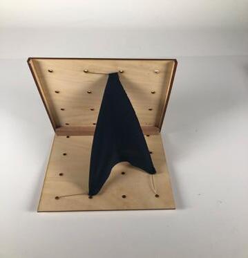
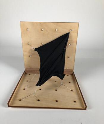
Analysis: The changes various anchor points such as in the case of using string and stretchy elastic fabric
Input: Cardboard allows for flexibility and durability including the creation of various forms based on how far the fabric is stretched while
Output: taking into account various forces that help shape the way the geometry is created as shown in the photo which depicts a triangular shaped form
Material used: Soldering Wire and string
Form: Various Forms and Geometries
Material used: Soldering Wire and string�
Material used: Soldering Wire Form: Various Forms and Geometries
PART A - Form Finding and Conceptual Framework


Iteration 01
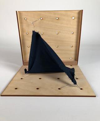
Analysis: The changes various anchor points such as in the case of using thinner wire and stretchy elastic fabric combined with Input: 5mm Plywood allows for flexibility and durability including the creation of various forms based on how far the fabric is stretched while Output: taking into account various forces that help shape the way the geometry is created as shown in the photo which depicts a triangular shaped form
Form: Triangular Shape:
Material used: Thin Wire
Iteration 02
Analysis: The changes various anchor points such as in the case of using thinner wire and stretchy elastic fabric combined with Input: 5mm Plywood allows for flexibility and durability including the creation of various forms based on how far the fabric is stretched while Output: taking into account various forces that help shape the way the geometry is created as shown in the photo which depicts a triangular shaped form
Form: Triangular Shape:
Material used: Thin Wire
Iteration
Analysis: The changes various anchor points such as in the case of using thinner wire and stretchy elastic fabric combined with Input: 5mm Plywood allows for flexibility and durability including the creation of various forms based on how far the fabric is stretched while Output: taking into account various forces that help shape the way the geometry is created as shown in the photo which depicts a triangular shaped form
Form: Unique Triangular Form
Material used: Soldering wire:
Front Side View 1 Side View 2
Front Side View 1
Front Side View
PART A - Form Finding and Conceptual Framework
A2� Catalogue of Forms and Iterations:


Iteration 04
Analysis: The changes various anchor points such as in the case of using thinner wire and stretchy elastic fabric combined with
Input: 5mm Plywood allows for flexibility and durability including the creation of various forms based on how far the fabric is stretched while
Output: taking into account various forces that help shape the way the geometry is created as shown in the photo which depicts a triangular shaped form
Iteration 05
Analysis: The changes various anchor points such as in the case of using thinner wire and stretchy elastic fabric combined with
Input: 5mm Plywood allows for flexibility and durability including the creation of various forms based on how far the fabric is stretched while
Output: taking into account various forces that help shape the way the geometry is created as shown in the photo which depicts a triangular shaped form
Iteration 06
Analysis: The changes various anchor points such as in the case of using thinner wire and stretchy elastic fabric combined with
Input: 5mm Plywood allows for flexibility and durability including the creation of various forms based on how far the fabric is stretched while
Output: taking into account various forces that help shape the way the geometry is created as shown in the photo which depicts a rectangular shaped form
Figure_ Catalogue Of Forms and Iterations
PART A - Form Finding and Conceptual Framework
A2� Catalogue of Forms and Iterations:


Iteration 07
Analysis: The changes various anchor points such as in the case of using thinner wire and stretchy elastic fabric combined with Input: 5mm Plywood allows for flexibility and durability including the creation of various forms based on how far the fabric is stretched while Output: taking into account various forces that help shape the way the geometry is created as shown in the photo which depicts a rectangular shaped form
Iteration 08
Analysis: The changes various anchor points such as in the case of using thinner wire and stretchy elastic fabric combined with Input: 5mm Plywood allows for flexibility and durability including the creation of various forms based on how far the fabric is stretched while Output: taking into account various forces that help shape the way the geometry is created as shown in the photo which depicts a triangular shaped form
Iteration 09
Analysis: The changes various anchor points such as in the case of using thinner wire and stretchy elastic fabric combined with
Input: 5mm Plywood allows for flexibility and durability including the creation of various forms based on how far the fabric is stretched
Output: taking into account various forces that help shape the way the geometry is created as shown in the photo which depicts a triangular shaped form Form: Unique Triangular Form Material used: Thin Wire Form: Unique Triangular Form
Figure_ Catalogue Of Forms and Iterations
PART A - Form Finding and Conceptual Framework


Iteration 01
Analysis: The changes in the amount of points placed along the skewers
Input: Changes in the various materials such as thinner elastic bands or thicker skewers or dowels�
Output: taking into account various forces that help shape the way the geometry is created as shown in the photo such as compression, pulling,
Iteration 02
Analysis: The changes in the amount of points placed along the skewers
Input: Changes in the various materials such as thinner elastic bands or thicker skewers or dowels�
Output: taking into account various forces that help shape the way the geometry is created as shown in the photo such as compression, pulling,
Iteration 03
Analysis: The changes in the amount of points placed along the skewers
Input: Changes in the various materials such as thinner elastic bands or thicker skewers or dowels�
Output: taking into account various forces that help shape the way the geometry is created as shown in the photo such as compression, pulling,
Figure_ Catalogue Of Forms and Iterations
PART A - Form Finding and Conceptual Framework
A2� Catalogue of Forms and Iterations:


Iteration 04
Analysis: The changes in the amount of points placed along the skewers
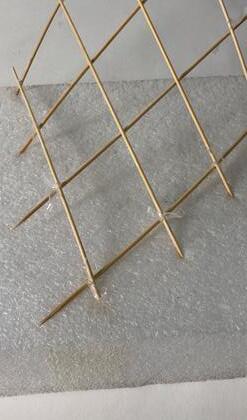
Input: Changes in the various materials such as thinner elastic bands or thicker skewers or dowels or sticking it into a piece of foam to allow for flexibility in creating different geometries.
Output: taking into account various forces that help shape the way the geometry is created as shown in the photo such as compression, pulling,
Iteration 05
Analysis: The changes in the amount of points placed along the skewers
Input: Changes in the various materials such as thinner elastic bands or thicker skewers or dowels or sticking it into a piece of foam to allow for flexibility in creating different geometries.
Output: taking into account various forces that help shape the way the geometry is created as shown in the photo such as compression, pulling,
Iteration 06
Analysis: The changes in the amount of points placed along the skewers
Input: Changes in the various materials such as thinner elastic bands or thicker skewers or dowels or sticking it into a piece of foam to allow for flexibility in creating different geometries.
Output: taking into account various forces that help shape the way the geometry is created as shown in the photo such as compression, pulling,
Figure_ Catalogue Of Forms and Iterations
Part A3 - Digital Iterations and Analysis
Week 3
PART A - Form Finding and Conceptual Framework
Iteration 01
Anaylsis: These iterations consist of a Tensil Structure Technique that has been manipulated using 4 divider curves that sit on the ends of the surface�
Upon further analysis it is better to create a grasshopper script that would easily manipulate the different forms�
Input:
Tension: The Force of the material been pulled by the 4 connector points creating movement of other areas
Output:
Stretching the geometry to create various forms�
Figure_ Digitial Iterations and Analysis

Iteration 02
These iterations consist of a Tensil Structure Technique that has been manipulated using 4 divider curves that sit on the ends of the surface�
Upon further analysis it is better to create a grasshopper script that would easily manipulate the different forms�
Input:
Tension: The Force of the material been pulled by the 4 connector points creating movement of other areas�
Output:
Stretching the geometry to create various forms�

Figure_ Digitial Iterations and Analysis
Anaylsis: These iterations consist of a Tensil Structure Technique that has been manipulated using 4 divider curves that sit on the ends of the surface�
Upon further analysis it is better to create a grasshopper script that would easily manipulate the different forms
Input:
Tension: The Force of the material been pulled by the 4 connector points creating movement of other areas
Output:
Stretching the geometry to create various forms�
Iteration 03
Figure_ Digitial Iterations and Analysis

Anaylsis: These iterations consist of a Tensil Structure Technique that has been manipulated using 4 divider curves that sit on the ends of the surface�
Upon further analysis it is better to create a grasshopper script that would easily manipulate the different forms
Input:
Tension: The Force of the material been pulled by the 4 connector points creating movement of other areas�
Output:
Stretching the geometry to create various forms
Iteration 04
Figure_ Digitial Iterations and Analysis

PART A - Form Finding and Conceptual Framework
Analysis: These iterations consist of a Tensil Structure Technique that has been manipulated using 4 divider curves that sit on the ends of the surface�
Upon further analysis it is better to create a grasshopper script that would easily manipulate the different forms�
Input:
Tension: The Force of the material been pulled by the 4 connector points creating movement of other areas�
Output:
Stretching the geometry to create various forms�
Iteration 05 A3�01 Digital Iterations: Final Form Finding Technique
Figure_ Digitial Iterations and Analysis
Analysis: These iterations consist of a Tensil Structure Technique that has been manipulated using 4 divider curves that sit on the ends of the surface�
Upon further analysis it is better to create a grasshopper script that would easily manipulate the different forms.

Analysis: These iterations consist of a Tensil Structure Technique that has been manipulated using 4 divider curves that sit on the ends of the surface�
Upon further analysis it is better to create a grasshopper script that would easily manipulate the different forms�
Input:
Tension: The Force of the material been pulled by the 4 connector points creating movement of other areas
Output:
Stretching the geometry to create various forms�
Figure_ Digitial Iterations and Analysis

Iteration 06
Input:
Tension: The Force of the material been pulled by the 4 connector points creating movement of other areas�
Output:
Stretching the geometry to create various forms
Iteration 07
Figure_ Digitial Iterations and Analysis

Analysis: These iterations consist of a Tensil Structure Technique that has been manipulated using 4 divider curves that sit on the ends of the surface�
Upon further analysis it is better to create a grasshopper script that would easily manipulate the different forms.
Input:
Tension: The Force of the material been pulled by the 4 connector points creating movement of other areas
Output:
Stretching the geometry to create various forms�
Figure_ Digitial Iterations and Analysis

Iteration 08
PART A - Form Finding and Conceptual Framework
A3�01 Digital Iterations: Final Form Finding Technique
Iteration 09
Anaylsis: These iterations consist of a Tensil Structure Technique that has been manipulated using 4 divider curves that sit on the ends of the surface�
Upon further analysis it is better to create a grasshopper script that would easily manipulate the different forms�
Input:
Tension: The Force of the material been pulled by the 4 connector points creating movement of other areas�
Output: Stretching the geometry to create various forms

Iteration 10
These iterations consist of a ruled surface that has been manipulated using 4 divider curves that sit on the ends of the surface
Upon further analysis it is better to create a grasshopper script that would easily manipulate the different forms.
Input: Tension: The Force of the material been pulled by the 4 connector points creating movement of other areas
Output: Stretching the geometry to create various forms�

Digitial Iterations and Analysis
Figure_
Figure_ Digitial Iterations and Analysis
Part A4 - Ideation and Speculative Design
From Micro to Macro
Week 4
PART A - Form Finding and Conceptual Framework

finding technique proposes a sitting area where people can have a rest or talk with friends and enjoy a coffee.
Application Across Scales

Meso Application: Building Facade For the Large Macro
Scale the form can be utilized in to a building that serves as a facade to the structure creating a unique architectural response through it’s curved elements�

Macro Application: Canopy/Shading Area
When looking at the form on a medium scale it could be transformed into a canopy or shading area allowing protection from the sun and weather events throughout the year�
Application Across Scales
Figure_
Figure_
Figure_ Application Across Scales
Figure_ Chosen Form
Part A5 - Preliminary Design Concept_Waterfront Intervention Week 5-6
WATER-FRONT INTERVENTION
Project Summary: My Technique is the Tensile Structure which works by placing anchor points at various intervals around the box which are manipulated by the fabric to form various geometries, the main part of the machine is a piece of stretched fabric where at each corner a piece of wire or string is attached which can then be used to create and manipulate the material that Is attached at various heights. Through this technique learned that various materials and fabric respond and act differently when they are placed under various variables and forces affecting durability and the flexibility of the form while still holding it shape. The technique influenced my concept by allowing me to create unique architectural responses while considering various forces that can be opened up to a wide range of options such as canopies and views. Using the form finding Technique and linking it to the studio brief was able to provide a unique response to the site while opening the spaces that currently closed the site and prevented user interaction and access. Our mixed use program aims to integrate multiple functions within a single structure or complex. These functions can include residential, commercial, retail, office, entertainment, and cultural spaces that various people can enjoy and use.


Wind Diagram
Circulation/Access Diagram
Views Diagram
Part A6 - Reflection and Conclusion
Week 6
PART A - Form Finding and Conceptual Framework
A6.01 Reflection and Conclusion
My key learnings and findings throughout the form finding process was that during the experiments I discovered that the forms vary each time pending on the location of the anchor points on the sides of the machine and where they are plotted which can dramatically influence and allow for further manipulation depending on the various fabric material that was used. Another key finding was experimenting with different wires to investigate how the fabric would be attached to the base of the machine this included thinner wires such as soldering wire which allowed for strength and durability but was limited to the flexibility, another material included thinner wires that were simpler to use which dramatically changed the flexibility and durability of the way the form reacted and stretched through the various forces that influenced.
The most surprising aspect that I learned while undertaking experiments into the Tensile Form Finding Technique was that the more anchor points you used, different geometries would form and can then be easily manipulated depending on the various forces that you consider such as compression, gravity and stretching which was through the various variations using different materials such as stretchy fabrics to see how it would react if the outside material was changed to plywood instead of Acrylic amongst others that can then be transferred into various architectural applications� The one thing I learned/took from the design activity since the start of the semester was that various forces can impact the way a particular geometry or fabric performs�

Figure_ Mapping Diagram
PART A - Form Finding and Conceptual Framework
Sources:
Various classifications for architectural form finding process. (n.d.). https://eijest.journals.ekb.eg/ article_144055_29753df002bca04c4580ab33683f2114�pdf
Architectural forming between form making and form finding towards form ... (n.d.-a). https://www.jaes.journals.ekb.eg/ article_19243_6df2a35a34e4f93af40c1cfeed0f8391�pdf
Zaha Hadid architects KnitCandela – Zaha Hadid Architects (n d ) https://www zaha-hadid com/design/knitcandela/
Pires, S� (2021, May 10)� 10 gravity-defying structures by Santiago Calatrava, legendary architect and Engineer� My Modern Met� https:// mymodernmet�com/santiago-calatrava-buildings/
Hnin, T. (2023, December 15). An introductory guide to form-finding in Architecture (2024). Novatr Prev OX. https://www.novatr.com/blog/formfinding-in-architecture
A bold circular bridge defines waterfront art gallery in Nanchang. Azure Magazine. (2019, June 6). https://www.azuremagazine.com/article/boldcircular-bridge-defines-waterfront-art-gallery-nanchang/
A bold circular bridge defines waterfront art gallery in Nanchang. Azure Magazine. (2019, June 6). https://www.azuremagazine.com/article/boldcircular-bridge-defines-waterfront-art-gallery-nanchang/
Network, L� L� A� (2015, April 30)� Giles Rayner and his mind bending water sculptures� Land8� https://land8�com/giles-rayner-and-his-mind-bendingwater-sculptures/
How tensile structures are revolutionizing the architecture industry? (n�d�)� https://parametric-architecture�com/how-tensilestructures-are-revolutionizing-the-architecture-industry/
In!, C� M� (n�d�)� Architecture design #1 - cable tensile structure� Parametric House� https://parametrichouse�com/architecture-design-1-2/
Cordless Drill� Hire Pro� (2024, January 12)� https://hireproonline�com�au/product/cordless-drill/
Projects / New York (Overview) - Santiago Calatrava – Architects & Engineers (n d -a) https://calatrava com/projects/world-trade-centertransportation-hub-new-york�html A0 - References and Online Sources
PART B - WATER FRONT PLACE-MAKING
Water-Front Placemaking Pre-design, Research and Schematic Design
Week 1-6
Part B1 - Design with Water Week 1 and 2
Part B - Water-front placemaking (Pre-design, Research and Schematic Design
B1: Design with water
Question 1: How can we transform water-fronts into dynamic environments that not only serve practical purposes but also offer opportunities for leisure, recreation and community engagement?
We can transform water-fronts into dynamic environments that not only serve practical purposes but also offer opportunities for leisure, recreation and community engagement, undertaking a holistic approach that takes into consideration a wide range of factors including urban planning, architecture, sustainability and community involvement, these include making public goals the primary consideration, creating a shared vision that can be used by people as they generate ideas, optimizing public access by giving people a continued access without the need to walk or take another route to access their destination through accessibility and inclusivity, sustainable design elements such as taking climate change into account ensuring we use eco friendly materials�
Any case studies of waterfront projects you have found successful and what factors have contributed to their success�
A case study that I have found successful is the Water-Front Art Gallery by Lacime Architects located in Nachang China, on the west bank of Xianghu Lake� The project aimed to fill in the gap in the landmark nodes that resulted the lack of buildings that were been constructed along the lake and the planning laws that contributed to those issues, while also aiming to elevate the terrain, preserve the urban green space through the integration of vegetation amongst the landscape of existing and newer developments�
The structure features a ring bridge that wraps around the building, providing a platform of access through the various locations which is integrated through a sculpture that acts as a connector but also as a response to the undercrossing tunnel that adjacent to Jiuzhou street� In relation to space planning, it features two courtyards, reception hall, exhibition hall and lounge, foyers while still maintaining the same form and geometry all the way round through it’s dynamic yet restrained and unique perception� The factors that contributed to the success of the project was the successful integration of water, vegetation/green spaces, simple rectangular geometry that reduced construction costs throughout�
Investigate and outline how water features can be integrated to stimulate the senses and create memorable experiences for users, fostering a deeper connection with the natural elements and surroundings�
To stimulate the senses and create memorable experiences for users, fostering a deeper connection with the natural elements and surroundings, water features can be integrated by considering the careful planning of various elements such as users that will use the space and how they will react emotionally and providing which can provide calming sights, sounds which prompts relaxation and a reduction in stress levels and can make changes to lifestyles� Other elements include costs and maintenance which can help reduce the amount of cleaning involved whilst reducing the amount of space a standard pool will take up making water features a more favorable investment�
Part B - Water-front placemaking (Pre-design, Research and Schematic Design
B1: Design with water

Figure 23 Theraputic Water-features created by Rock N Landscapes
The healing power of water featuresrock n water landscapes� Rock N Water
Landscapes - Contact us today at 612865-4504� (2018, January 24)� https:// rocknwaterlandscapes�com/the-healingpower-of-water-features/

Figure 25 Theraputic Waterfeatures created by Rock N Landscapes
The healing power of water featuresrock n water landscapes� Rock N Water
Landscapes - Contact us today at 612865-4504� (2018, January 24)� https:// rocknwaterlandscapes�com/the-healingpower-of-water-features/

Figure 24 Trickling Water Fall Fountains designed by Dan technologies
Trickling water fall fountains at best price in Delhi - ID: 4370845: DANTECH Technologies� at Best Price in Delhi - ID: 4370845 | DANTECH TECHNOLOGIES� (n�d�)� https://www� exportersindia�com/product-detail/tricklingwater-fall-fountains-4370845�htm

Figure 26 Castle hill water sculpture topiary� Photo credit: Clive Nichols Network, L� L� A� (2015, April 30)� Giles Rayner and his mind bending water sculptures� Land8� https://land8�com/giles-rayner-and-his-mindbending-water-sculptures/

Figure 27 Gallery of waterfront art gallery / lacime architects - 3� ArchDaily� (n�d�)� https://www�archdaily� com/907733/waterfront-art-gallerylacime-architects/5c139bc708a5e54ba d000d1f-waterfront-art-gallery-lacimearchitects-photo?next_project=no

Figure 28 Gallery of waterfront art gallery / lacime architects - 3�
ArchDaily� (n�d�)� https://www�archdaily� com/907733/waterfront-art-gallerylacime-architects/5c139bc708a5e54ba d000d1f-waterfront-art-gallery-lacimearchitects-photo?next_project=no

Figure 29 Gallery of waterfront art gallery / lacime architects - 3�
ArchDaily� (n�d�)� https://www�archdaily� com/907733/waterfront-art-gallerylacime-architects/5c139bc708a5e54ba d000d1f-waterfront-art-gallery-lacimearchitects-photo?next_project=no

Figure 30 Gallery of waterfront art gallery / lacime architects - 3� ArchDaily� (n�d�)� https://www�archdaily� com/907733/waterfront-art-gallerylacime-architects/5c139bc708a5e54ba d000d1f-waterfront-art-gallery-lacimearchitects-photo?next_project=no
Part B2 - Precedent Studies and Diagramming
Week 3 and 4
PART B - Waterfront placemaking (Pre-design, Research and Schematic Design
B2�01 Precedent Study and Diagramming
WATER-FRONT ART GALLERY
Year: 2018
Location: Nanchang China
Team: Lacime Architects led by Zhaoqing Song
Status: Completed
Area: 1192m2
The the Water-Front Art Gallery by Lacime Architects located in Nachang China, on the west bank of Xianghu Lake. The project aimed to fill in the gap in the landmark nodes that resulted the lack of buildings that were been constructed along the lake and the planning laws that contributed to those issues, while also aiming to elevate the terrain, preserve the urban green space through the integration of vegetation amongst the landscape of existing and newer developments�
The structure features a ring bridge that wraps around the building, providing a platform of access through the various locations which is integrated through a sculpture that acts as a connector but also as a response to the undercrossing tunnel that adjacent to Jiuzhou street� In relation to space planning, it features two courtyards, reception hall, exhibition hall and lounge, foyers while still maintaining the same form and geometry all the way
PART B - Waterfront placemaking (Pre-design, Research and Schematic Design
B2�01 Precedent Study and Diagramming

Figure 31 Gallery of waterfront art gallery / lacime architects - 3. ArchDaily. (n.d.). https://www.archdaily.com/907733/waterfront-artgallery-lacime-architects/5c139bc708a5e54bad000d1f-waterfront-art-gallery-lacime-architects-photo?next_project=no
PART B - Waterfront placemaking (Pre-design,
B2�01 Precedent Study and Diagramming
Perspective View of Precedent Study
Figure_ Perspective View of Precedent Diagram
PART B - Waterfront placemaking (Pre-design, Research and Schematic Design
B2�01 Precedent Study and Diagramming
Key Elements
Internal and External Circulation Paths
The water-front art gallery by Lacime Architects is split over 2 levels with reception, courtyard, water access and officespaces on the ground floor with a further 3 rooms on the first floor consisting of services, exhibition space and a second reception area with access through the walkway with views over the water�
Circulatation was a key element when designing the Water-Front Art Gallery Due to the structure been two stories in height, with amenties both on the ground and first floor and with water playing a major role in the layout, the designer intended to maximise the space by providing a walkway along the water that connects both the first floor and second floor levels whilist giving people a sense of calmness and feeling that they are near the way while sorrounded by vegetation and ventiliation within the various spaces This subsquently allows for the users to experience calmer moods and positive mindsets and stunning views overlooking the city and surrounding suburb�
In our Design, circulation would play a significant give each space flexibility and allow for cross ventilation to flow through the space, however a space like a exhibition area would allow for students to pin up their work or can be used for a variety of other things�
Figure_ Ground Floor Circulation Diagram
Figure_ First Floor Circulation Diagram
PART B - Waterfront placemaking (Pre-design, Research and Schematic Design
B2�01 Precedent Study and Diagramming
Figure_ Ground Floor Vertical Circulation Diagram
Figure_ First Floor Vertical Circulation Diagram
PART B - Waterfront placemaking (Pre-design, Research and Schematic Design
B2�01 Precedent Study and Diagramming
Precedent Study
Case Study: Water-Front Art Gallery by Lacime Architects
Key Elements
Zoning and Program Spaces
The water-front art gallery by Lacime Architects is split over 2 levels with reception, courtyard, water access and officespaces on the ground floor with a further 3 rooms on the first floor consisting of services, exhibition space and a second reception area with access through the walkway with views over the water�
Zoning was a key element when designing the Water-Front Art Gallery� Due to the structure been two stories in height, with amenties both on the ground and first floor and with water playing a major role in the layout, the designer intended to maximise the space by providing a walkway along the water that connects both the first floor and second floor levels whilist giving people a sense of calmness and feeling that they are near the way while sorrounded by vegetation and ventiliation within the various spaces� This subsquently allows for the users to experience calmer moods and positive mindsets and stunning views overlooking the city and surrounding suburb�
In our Design, an open plan design with views to the city and other areas would give each space flexibility and allow for cross ventilation to flow through the space, however a space like a exhibition area would allow for students to pin up their work or can be used for a variety of other things�
Figure_ Zoning and Program Spacing Diagram
PART
B - Waterfront placemaking (Pre-design, Research and Schematic Design
B2�01 Precedent Study and Diagramming
Precedent Study
Case Study: Water-Front Art Gallery by Lacime Architects


Figure_ Isometric Diagram showing Components of Structure
Figure_ Isometric Diagram showing Materaility
PART B - Waterfront placemaking (Pre-design, Research and Schematic Design
B2�01 Precedent Study and Diagramming
Precedent Study
Case Study: Water-Front Art Gallery by Lacime Architects
Key Elements
Access and Transporation
Access to the site was a key element when designing the Water-Front Art Gallery Due to the structure been two stories in height, with amenities both on the ground and first floor and with water playing a major role in the layout, the designer intended to maximise the access by providing a range of entrance points around the water ramp access and at the front of the site that connects both the first floor and second floor levels and throughout the building allowing people to get around the building
In our Design, Access would play a significant give each space flexibility and allow for the community and students to move through the space and experience the various buildings on-site and enjoy the experience while also providing a range of entrance points around the site allowing access from multiple directions
Figure_ Access Diagram
PART B - Waterfront placemaking (Pre-design, Research and Schematic Design
B2: Precedent Study and Diagramming
Precedent Study
Case Study: Water-Front Art Gallery by Lacime Architects
Key Elements
Sun Diagram
Exposure to Sun and maximizing it’s potential was a key element when designing the Water-Front Art Gallery Due to the structure been two stories in height, with amenities both on the ground and first floor and with water playing a major role in the layout, the designer intended to maximise light by providing a floor to ceiling height windows along the water ramp access that connects both the first floor and second floor levels and throughout the building allowing the structure to get a lot of light and cross ventilation whilst giving people a sense of calmness and feeling that they are near the way while surrounded by vegetation and ventilation within the various spaces This subsequently allows for the users to experience calmer moods and positive mindsets and stunning views overlooking the city and surrounding suburbs�
In our Design, Sun Diagram would play a significant give each space flexibility and allow for cross ventilation to flow through the space and allow for a lot of light to flow through the building however a space like an exhibition area and reception spaces would allow for students and the community to view historical artifacts about the history of the site and ask for any questions at the reception
Figure_ Sun Analysis/Orientation Diagram
PART B - Waterfront placemaking (Pre-design, Research and Schematic Design
B2: Precedent Study and Diagramming
Precedent Study
Case Study: Water-Front Art Gallery by Lacime Architects
Key Elements
Sustainability
Sustainability was a major consideration when designing the water-front art gallery as the architects wanted to incorporate many sustainable elements such as double glazing, natural lighting allowing for cross ventilation, efficient heating, cooling and ventilation systems, when all combined would allow for a comfortable enviroment for the occupants and visitors as they walked through the 2 storey structure
In our Design, Sustainability would play a significant as our proposed site has no greenspace making the site unattractive to passing by visitors and unwelcoming, however it would help save costs through construction amongst other things
Figure_ Sustainable Elements Diagram
PART B - Waterfront placemaking (Pre-design, Research and Schematic Design
B2: Precedent Study and Diagramming
Precedent Study
Case Study: Water-Front Art Gallery by Lacime Architects
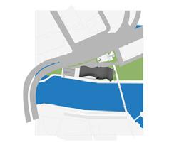
Site Comparison (731-739 Flinders Street Nanchang City China
Site Comparison (731-739 Flinders Street
Even though the difference in the topograpgy and scale between the two sites is different however still both have the same similarities where the arrangements of programs in Lacime’s architects structure is an important factor for our site�
PART B - Waterfront placemaking (Pre-design, Research and Schematic Design
B2: Precedent Study and Diagramming
Precedent Study
Case Study: Water-Front Art Gallery by Lacime Architects
Views Diagram
The Idea of having all spaces with views to the Yarra river becomes an important aspect of our design which allows natural light
Program and Zoning
The idea of having the spaces face out to the yarra river becomes a crucial factor in our design to engage the public, where the possiblity to include a ramp with views to river can also be included�
Massing Diagram
The new structure can act as a continuation of the existing structures, with the same approach applied to the hertiage listed cargo shed 5 and the site�
Part B3 - Site Analysis
Week 1-3
PART
B3: Site Analysis Site Analysis
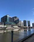
731-739 Flinders Street History
731-739 Flinders Street South Yarra predominantly a waterfront area centered on the banks of the Yarra-River has long been an iconic element in helping Melbourne shape its identity� From the early history of becoming a hunting ground of the Wurundjeri people thus cementing its significance and relationship, to becoming a naval dock during WW1 and WW2 and an entry hub for many immigrants coming to Australia to give us a better life� However, in the many years since then the area has become irrelevant and unattractive for many residents and to the city of Melbourne�
However whilst there is public transport access such as tram routes and bus interchange stops the site over the years has long become ignored and neglected by the residents of Melbourne and the wider Melbourne community due to its lack of attractiveness and places to go and enjoy a night out while enjoying water-front views along the Yarra-River
PART B - Waterfront placemaking (Pre-design, Research and Schematic Design
B3: Site Analysis
Site Analysis
The Mission to Seafarers’s Building
The mission to seafearer’s building formely known as Mission to seamen located to the north east of the site, is a rendered brick building built in 1917is of historical and cultural significance and is listed on the Victorian Heritage List

32 Mission to Seafarers Building Taken from
The Goods Shed
The mission to seafearer’s building formely known as Mission to seamen located to the north east of the site, is a rendered brick building built in 1917is of historical and cultural significance and is listed on the Victorian Heritage List

Figure 33 (Heritage Listed Goods Shed Sourced From Architecture and Design com Heritage listed Goods Shed no�5’s retention works completed� Architecture & Design� (n�d�)� https://www�architectureanddesign�com� au/news/riverlee-seafarers-site-retention-works
Figure
Streetview by Goce Lazareski
PART B - Waterfront placemaking (Pre-design,
B3: Site Analysis
Site Analysis
3 Tonne Crane
The three tonne crane located on the site alongside the goods shed is significant as it demonstrated the post cargo handling methods of the pre containerisation in the Port of Melbourne, the crane considered to be the most historically and technologically advanced piece of history

PART
B3: Site Analysis
Site Analysis


Figure_Existing Site Conditions

Figure_Sun Analysis
Figure_Accessibility
Figure_Transportation
PART B -
B3: Site Analysis
Site Analysis
Figure_views to river
Figure_Educational Locations
Figure_dinning Locations
Figure_Wind Analysis
Kangan Institute Vocational College
Monash College Campus
B3: Site Analysis
Site Analysis
Design Opportunities
Once we had examined the site it was important for us as a team to begin looking at the design opportunities the site presented to us early on� Through this we wanted to explore how we could better connect people with the surrounding context, through the integration of the following elements such as
- Green spaces
- Accessbilitity
- Sustainability�
-Interaction with Water�
But more specificially we wanted to provide a design proposal that would provide a direct connection between the water and the land through spaces such as interactive water zones and boat tours allowing the proposal to represent a new standard in urban design and combining the ever changing dynamics of water with both
PART
B3: Site Analysis
Site Analysis
Design Opportunities
Design Opportunity 1: Using Greenspace to better connect the community and integrated vegetation within the space�

Figure 34 The Benefits of using Greening Urban Spaces Penso. (2022, March 19). The benefits of “greening” urban spaces - programmed au: The power of a job done right Programmed AU | The Power of a Job done Right https://programmed.com.au/the-benefits-of-greeningurban-spaces/
Design Opportunity 2: Implementing Sustainable elements within the building and within the facade�

Figure 35 PARKROYAL Collection
Pickering incorporates the tropical climate of Singapore into the building� iStock Editorial/Getty Images
PART B - Waterfront placemaking (Pre-design, Research and Schematic Design
B3: Site Analysis
Site Analysis
Design Opportunities
Design Opportunity 3:
Providing a water-interactive zone within the proposal to enhance a seamless and dynamic connection between the site and Yarra River

36 Example of Water Integration with Buildings Cao, L� (2020, January 1)� Innovative uses of water in architecture� ArchDaily� https://www�archdaily� com/931070/innovative-uses-of-water-in-architecture
Design Opportunity 4:
Providing a unqiue entrance to the proposal allowing for the building to set apart from the rest in the sorrounding providing a unique response providing a modern feel�

37 Modern Building Entrance Condominium entrance, entrance design, facade architecture� Pinterest� (2017, August 25)� https://www� pinterest�com�au/pin/325103666843271901/
Figure
Figure
PART B - Waterfront placemaking (Pre-design, Research and Schematic Design
B3: Site Analysis:
Site Analysis
Design Opportunities
- Works as a Scientist at CSIRO in the CBD
- 32 Years Old
- Relocated to Docklands to be closer to Campus
- Loves the outdoor space and jogging in the afternoon
- Stay at home dad, loves to take care of his children when his wife isn’t home.
JACK
- Studies Photography at RMIT Melbourne Campus
- 24 Years Old
- Relocated to Docklands to be closer to Campus
- Loves the outdoor space and jogging in the afternoon and taking photos
- Studies Biodiversity at RMIT Melbourne Campus
- 27 Years Old
- Relocated to Docklands to be closer to Campus
- Loves the outdoor space and jogging in the afternoon
ALEX
Part B4 - Water Front Design Vision and Return Brief Week 1-4
B4: Waterfront design vision and return brief�
Project Name
WELCOME TO
DREAMTIME YARRA-LIVING
PART B - Waterfront placemaking (Pre-design, Research and Schematic Design
B4: Waterfront design vision and return brief�
Design Proposal

STUDENT ACCOMDATION SPACES
LIVING SPACES/OPENPLANNING ZONES
SLEEPING QUARTERS/PRIVATE SPACES
VIEW TO YARRA RIVER
CULTURAL SPACES

THEATRE AREAS TO LEARN ABOUT HISTORY
CULTURAL LEARNING SPACES
LIVE INDIGENOUS/FIRST NATION SHOWS
FERRIES/BOAT TOURS
ENTERTAINMENT RESIDENTIAL
DREAM TIME YARRA-LIVING
PROPOSAL
CAFE AREAS
SMALL SHOPPING SHOPS
RESTRAUANTS

RETAIL SPACES
COMMERICAL

RESEARCH LABS
MEETING SPACES
OFFICE SPACES

GATHERING SPACES
EVENTS/PERFORMANCES
CINEMAS
Figure_ Dream Time Yarra Living Proposal
B4: Waterfront design vision and return brief�
Key Words and Design Issues
Accessibility
Creating a Space that is inviting and accessible to the community which has become a primary concern in our project given the current site conditions�
Sustainability
Prioritizing and integrating sustainable elements through cutting edge design elements that support both energy efficient and water conservation and providing a better air quality around the site
Cultural
Preserving the cultural significance of the space by looking at and integrating ways that both respect and maintain the site’s historical legacy both now and into the future�
Connection with Water
Improving the quality of the water ensuring that it is a safe enviroment for all users to enjoy�
PART B - Waterfront placemaking
B4: Waterfront design vision and return brief�

STUDENT ACCOMDATION SPACES
LIVING SPACES/OPENPLANNING ZONES
RESIDENTIAL
SLEEPING QUARTERS/PRIVATE SPACES
VIEW TO YARRA RIVER
CULTURAL SPACES

THEATRE AREAS TO LEARN ABOUT HISTORY
CULTURAL LEARNING SPACES
LIVE INDIGENOUS/FIRST NATION SHOWS
FERRIES/BOAT TOURS
DREAM TIME YARRA-LIVING
RETURN BRIEF
CAFE AREAS
SMALL SHOPPING SHOPS
RESTRAUANTS

RETAIL SPACES
COMMERICAL

RESEARCH LABS
MEETING SPACES
OFFICE SPACES
ENTERTAINMENT
CINEMAS
GATHERING SPACES
EVENTS/PERFORMANCES
PART B - Waterfront placemaking (Pre-design, Research and Schematic Design
B4: Waterfront design vision and return brief� Design Vision
INTERACTING WITH WATER

INTERACTIVE WATER ZONES
RESEARCH LABS
FERRIES/BOAT TOURS
WATER VIEWS TO SOUTH YARRA
ACCESSIBILITY

ATTRACTION
INDOOR/OUTDOOR SPACES PATHWAYS
CIRCULATION AROUND THE SITE.
DREAM TIME YARRA-LIVING
DESIGN VISION
THEATRE AREAS TO LEARN ABOUT HISTORY
CULTURAL SYMBOLS
LIVE INDIGENOUS/FIRST NATION SHOWS
CULTURAL TOURS

CULTURAL CONNECTION
SUSTAINABILITY

NATURAL LIGHTING
IMPROVING AIR QUALITY
WATER CONSERVATION
NATURAL MATERIALS
NATURE INSPIRED

INTEGRATION WITH LANDSCAPE
GREENERY AND PLANTING
ROOFTOP GARDENS
Figure_ Dream Time Yarra Living Design Vision and Scheme
Part
B5 - Pre-Design Stage and Mass Studies
Week 4-6
PART B - Waterfront placemaking (Pre-design, Research and Schematic Design
B5: Pre-design stage and mass studies
Massing and Typologies
Introduction to Programs

EXISTING SITE CONDITIONS

INTRODUCING PROGRAMS
PART B - Waterfront placemaking (Pre-design, Research and Schematic Design
B5: Pre-design stage and mass studies
Massing and Typologies


PART B - Waterfront placemaking (Pre-design, Research and Schematic Design
B5: Pre-design stage and mass studies
Massing and Typologies
Massing Diagram Iterations


PART B - Waterfront placemaking (Pre-design,
B5: Pre-design stage and mass studies
Massing and Typologies
PART B - Waterfront placemaking (Pre-design, Research and Schematic Design
B5: Pre-design stage and mass studies
Massing
and Typologies
User Experience
PART B - Waterfront placemaking (Pre-design,
B5: Pre-design stage and mass studies
Massing and Typologies
Circulation and Transportation
Iteration
PART B - Waterfront placemaking (Pre-design, Research and Schematic Design
B5: Pre-design stage and mass studies
Massing and Typologies
Sun Diagram
PART B - Waterfront placemaking (Pre-design, Research and Schematic Design
B5: Pre-design stage and mass studies
Massing and Typologies
Design Option Ideas


Figure 39 Proposed Design Option for Water-Front Intervention Created by Abdul Khaliq Shahab Collaborated by Jack Yalda and Goce Lazareski as part of ST1_Group 7 for WaterFront Intervention
Figure 38 Design Option for Water-Front Intervention Created by Jack Yalda Collaborated by Abdul Khaliq Shahab and Goce Lazareski as part of ST1_Group 7 for WaterFront Intervention
PART B - Waterfront placemaking (Pre-design, Research and Schematic
Design
B5: Pre-design stage and mass studies
Massing and Typologies
Chosen Design Option

Figure 40 Proposed/Chosen Option for Water-Front Intervention Created by Abdul Khaliq Shahab Collaborated by Jack Yalda and Goce Lazareski as part of ST1_Group 7 for WaterFront Intervention
PART B - Waterfront placemaking (Pre-design, Research and Schematic Design
B5: Pre-design stage and mass studies

Chosen Design Diagrams


Massing and Typologies


Figure 43 Form Diagram for Water-Front Intervention Created by Abdul Khaliq Shahab Collaborated by Jack Yalda and Goce Lazareski as part of ST1_Group 7 for WaterFront Intervention
Figure 42 Axonometric Diagram for Water-Front Intervention Created by Abdul Khaliq Shahab Collaborated by Jack Yalda and Goce Lazareski as part of ST1_Group 7 for WaterFront Intervention
Figure 41 Axonometric Diagram for Water-Front Intervention Created by Abdul Khaliq Shahab Collaborated by Jack Yalda and Goce Lazareski as part of ST1_Group 7 for WaterFront Intervention
PART B - Waterfront placemaking (Pre-design, Research and Schematic Design
B5: Pre-design stage and mass studies
Massing and Typologies
Ferry Station, Concept Refurbishment Process

Figure 44 Good-Shed Concept Refurbishment Process for Water-Front Intervention Created by Jack Yalda Collaborated by Abdul Khaliq Shahab and Goce Lazareski as part of ST1_Group 7 for WaterFront Intervention
PART B - Waterfront placemaking (Pre-design, Research and Schematic Design
B5: Pre-design stage and mass studies
Early Massing Models completed early on Massing and Typologies

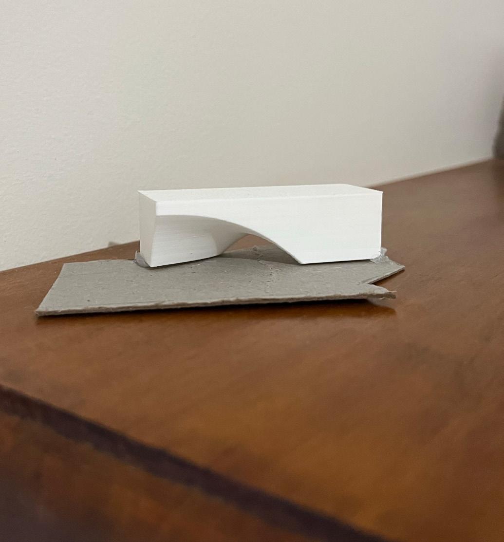
Figure 45 Small Massing Concept Model for Water-Front Intervention Created by Jack Yalda Collaborated by Abdul Khaliq Shahab and Goce Lazareski as part of ST1_Group 7 for WaterFront Intervention
Figure 46 Small Massing Concept Model for Water-Front Intervention Created by Jack Yalda Collaborated by Abdul Khaliq Shahab and Goce Lazareski as part of ST1_Group 7 for WaterFront Intervention
Part B6 - Reflection and Conclusion
Week 4-6
PART B -
Waterfront placemaking (Pre-design, Research and Schematic Design
B6: Reflection and Conclusion
Reflection and Conclusion
Reflection
Based on the feedback of the initial mid semester proposal, we were to include at better enhancing and further developing our design based on our site analysis and issues that we sought to address throughout our design, this included further developing the main program, circulation from the mixed-use building to the student accommodation and deeper focus on sustainability, materiality, integration with water. Initially we intended to have the one building on site that would connect with the ferry station, which would allow for more greenery throughout the site furthermore it would utilize the space to allow the occupants to feel a unique connection and attractiveness with the proposed site and with the Yarrariver.
Moving on into schematic designs our group will work on strengthening our programs and connection between the structures and ensuring that the circulation and zoning within the site works cohesively. The Part B process allowed me think about how the positing of programs between public and private areas can help enhance the user experience and how a project progresses from concept to becoming reallife.
PART C - Form Finding to Water-Front Place-Making
Design Development Week 7-11
Part C1 - Project Summary
Week 7-11
PART C - From Form Finding to Water-front Placemaking (Design Development)
C1: Project Summary
Concept Development
731-739 Flinders Street Project Statement
Dream Time Yarra - Living
Dream time Yarra Living is a visionary mixed-use development located on the last remaining piece of Melbourne’s original waterfront precinct, designed to integrate urban luxury with natural beauty. The Project features a ferry station offering historical and cultural tours providing a seamless blend of educational and recreational opportunities with facilities such as a ticket booth, waiting area, docking zone, café and an information center showcasing some of Melbourne’s rich heritage�
Adjacent to the ferry station is the state-of-the-art marine research lab and offices dedicated to water quality research equipped with advanced laboratories, office spaces, conference rooms, storage facilities and outdoor seating areas designed to foster scientific discovery and innovation while providing education outreach to millions of students and people through workshops and lectures�
Located on the rooftops is the buzzing restaurant with panoramic 360-degree views to the Yarra River offering a unique dining experience featuring spacious indoor and outdoor seating and rooftop gardens designed to be accessible to all providing a luxurious yet inclusive dinning environment
The development also includes modern business offices offering flexible office suites, meeting rooms, co-workers spaces and an onsite fitness center. These offices aim to support a dynamic business community.
Cultural shows are hosted on the ground floor where a versatile performance hall, exhibition and retail spaces create a vibrant hub, these spaces are designed to support a wide range of artistic and cultural activities fostering community engagement and cultural expression showcasing Melbourne’s rich aboriginal heritage�
Additionally, the development also features student apartments each design for comfort and convenience� Each apartment is fully furnished and comes with study rooms, common areas, laundry facilities and recreational zones catering for a wide range of students�
Part C2 - Precedent Study
Week 7-11
PART C - From Form Finding to Water-front Placemaking (Design Development)
C2: Precedent Study
Concept Development
Case study 1 - World Trade Centre Transporation Hub
Jockey Club i Village
Year: 2018-2024
Location: Hong Kong China
Team: Zaha Hadid and L & O
Client: Hong Kong University of Science and Technology
Status: Under Construction
The student Residences development designed by Zaha Hadid and Leigh and Orange located in Hong Kong China was created in response to the urgent demand for new residential facilities and halls within the campus that was inspired by the university’s mission to harness technology and innovation to provide solutions to solve today’s critical global issues. The design itself comprises of 3 main components, the Central Spine, The Courtyards and the Clusters with a considered approach to modular construction.
The Central Spine features a roofline that will act as a public space accessible to residents, nonresidential students and staff during the day.
The Court yards act as a quiet break-out space and various functions depending on the location and landscape.
The clusters which feature Linear, V Cluster and Y Cluster each with various bed capacities, double and single occupancy, bedrooms, bathroom and various configurations of communal spaces.

47 Gallery of zaha hadid architects designs student residence development at the Hong Kong University of Science and Technology - 5 ArchDaily (n d ) https://www archdaily com/954470/zaha-hadidarchitects-designs-student-residence-development-at-the-hongkong-university-of-science-and-technology/5ff4438163c017c df9000395-zaha-hadid-architects-designs-student-residence-developmentat-the-hong-kong-university-of-science-and-technology-image?next_ project=no
Figure
PART C - From Form Finding to Water-front Placemaking (Design Development)
C2: Precedent Study
Case study 2 - Yeoui Naru Ferry Terminal Concept Development
Yeoui Naru Ferry Terminal
Situated on Yeouido Island in Seoul South Korea, the Yeoui Naru Ferry Terminal is a nortable architectural project known as Yeoui Naru Ferry Terminal. The terminal designed by Mass Studies in colloboration with architect Minsuk Cho who are well known for their creative and organic architecture that seamlessly blends in with the Han River and the surrounding urban enviroment.
Important Elements:
The structure features an organic form where the curves blend in with the riverbank and resemble natural forms throughout. It also features a multiple levels each serving their own unique purpose such as observation platforms, cafes and waiting areas.

Figure 48 Inspiration for Ferry Station
Yeoui-Naru Ferry Terminal� Luca Poian Forms� (2023, May 23)� https:// www�lucapoianforms�com/projects/yeoui-naru-ferry-terminal/?fbcl id=IwZXh0bgNhZW0CMTAAAR2N-KM70l6xe6l2FhMmUOOZ6wnutl_ ZgE7M-nQLF2JC5HqLwyakZQUGTRM_aem_AWhEpCsC1fmWwSUeF06IHotYmCp1P6NkX-m7EJl9jySPWqfCz7nGmUxjm6vgjWd2hCEdQyebYHwCSpnnAFzls6
Part C3 - Revised Design Vision and Analysis
Week 7-11
PART C - From Form Finding to Water-front Placemaking (Design Development)
C2: Precedent Study
Concept Development
Key words and Issues our project seeks to tackle.
Accessibility
Creating a Space that is inviting and accessible to the community which has become a primary concern in our project given the current site conditions�
Sustainability
Prioritizing and integrating sustainable elements through cutting edge design elements that support both energy efficient and water conservation and providing a better air quality around the site
Cultural
Preserving the cultural significance of the space by looking at and integrating ways that both respect and maintain the site’s historical legacy both now and into the future�
Connection with Water
Improving the quality of the water ensuring that it is a safe enviroment for all users to enjoy�
PART C - From Form Finding to Water-front Placemaking (Design Development)
C3: Revised Design Vision and Analysis
Concept Development
Revised Design Proposal
RESIDENTIAL

CULTURAL SPACES

DREAM TIME YARRA-LIVING
PROPOSAL


RETAIL SPACES

ENTERTAINMENT
PART C - From Form Finding to Water-front Placemaking (Design Development)
C3: Revised Design Vision and Analysis
Concept Development
Revised Design Vision


DREAM TIME YARRA-LIVING
DESIGN VISION


PART C - From Form Finding to Water-front Placemaking (Design Development)
Accessbility DIAGRAM
Site Provides an advantage to atract and interact with multiple user groups
TRANSPORTATION DIAGRAM
Accessible Public Transport within Proximity of Site
PART C - From Form Finding to Water-front Placemaking (Design Development)
C3: Revised Design Vision and Analysis
Concept Development
Revised Site Analysis


Figure 49 Weaknesses for Water-Front Intervention made By Jack Yalda Collaborated by Abdul Khaliq Shahab and Goce Lazareski as part of ST1_Group 7 for WaterFront Intervention
Figure 50 Proposed Site for Water-Front Intervention made By Jack Yalda Collaborated by Abdul Khaliq Shahab and Goce Lazareski as part of ST1_Group 7 for WaterFront Intervention
Figure 51 Existing Site Analysis for Water-Front Intervention made By Jack Yalda Collaborated by Abdul Khaliq Shahab and Goce Lazareski as part of ST1_Group 7 for WaterFront Intervention
PART C - From Form Finding to Water-front Placemaking (Design Development)
C3: Revised Design Vision and Analysis
Concept Development
Revised Site Analysis

Lack of Water Qualuty
Figure 52 Lack of Green Space for Water-Front Intervention
Diagram made By Jack Yalda Collaborated by Abdul Khaliq Shahab and Goce Lazareski as part of ST1_Group 7 for WaterFront Intervention

Lack of Water Quality
Figure 53 Lac of Water Quality for Water-Front Intervention Diagram made By Jack Yalda Collaborated by Abdul Khaliq Shahab and Goce Lazareski as part of ST1_Group 7 for WaterFront Intervention
Part C4 - Design Iterations
Week 7-11
PART C - From Form Finding to Water-front Placemaking (Design Development)
C4: Design Iterations
Concept Development
Guide to Iterations

Figure 54 Iterations and Design Options for Water-Front Intervention made By Jack Yalda, Collaborated by Goce Lazareski and Abdul Khaliq Shahab as part of ST1_Group 7 for WaterFront Intervention

Figure 55 Iterations and Design Options for Water-Front Intervention made By Jack Yalda, Collaborated by Goce Lazareski and Abdul Khaliq Shahab as part of ST1_Group 7 for WaterFront Intervention

Figure 56 Iterations and Design Options for Water-Front Intervention made By Jack Yalda, Collaborated by Goce Lazareski and Abdul Khaliq Shahab as part of ST1_Group 7 for WaterFront Intervention
PART C - From Form Finding to Water-front Placemaking (Design Development)
C4: Design Iterations
Concept Development
Iteration 01

57 Design Iteration 01 for Water-Front Intervention By Jack
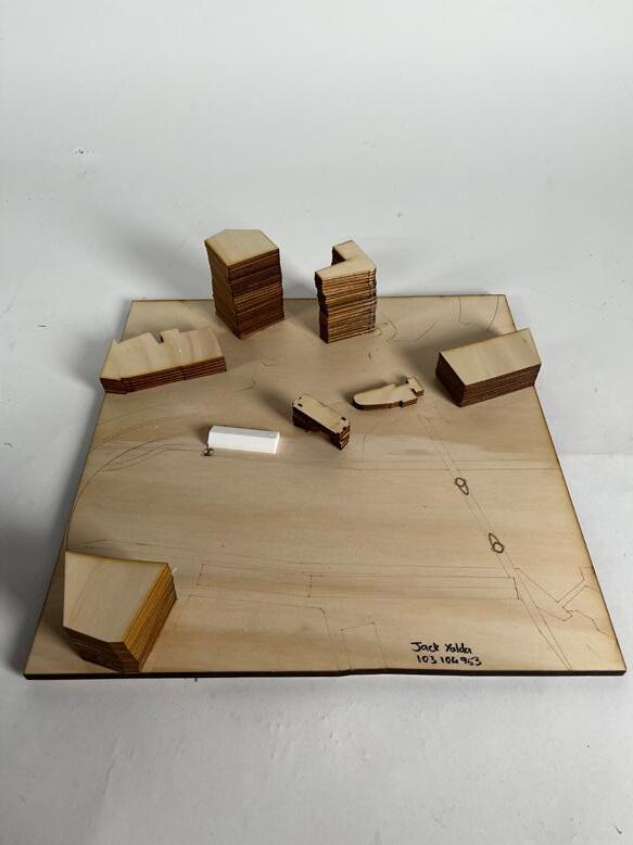
Site
01
Figure
Yalda Collaborated by Goce Lazareski and Abdul Khaliq Shahab as part of ST1_Group 7 for WaterFront Intervention
Figure 58 Physical
Model
for Water-Front Intervention By Jack Yalda Collaborated by Goce Lazareski and Abdul Khaliq Shahab as part of ST1_Group 7 for WaterFront Intervention
PART C - From Form Finding to Water-front Placemaking (Design Development)
C4: Design Iterations
Concept Development
Iteration 01


Figure 61 Proposed Design Option for Water-Front Intervention Created by Abdul Khaliq Shahab Collaborated by Jack Yalda and Goce Lazareski as part of ST1_Group 7 for WaterFront Intervention
Figure 59 Axonometric Diagram for Water-Front Intervention Created by Abdul Khaliq Shahab Collaborated by Jack Yalda and Goce Lazareski as part of ST1_Group 7 for WaterFront Intervention
Figure 60 Program Diagram for Water-Front Intervention Created by Abdul Khaliq Shahab Collaborated by Jack Yalda and Goce Lazareski as part of ST1_Group 7 for WaterFront Intervention
PART C - From Form Finding to Water-front Placemaking (Design Development)
C4: Design Iterations
Concept Development
Iteration 02

Figure 62 Iteration 2 Water-Front Intervention made ByJack Yalda, Collaborated by Goce Lazareski and Abdul Khaliq Shahab, as part of ST1_ Group 7 for WaterFront Intervention

Figure 63 Program diagram for Water-Front Intervention made By Abdul Khaliq Shahab, Collaborated by Goce Lazareski and Jack Yalda as part of ST1_Group 7 for WaterFront Intervention

Figure 64 Physical Iteration 2 Site Model 01 for Water-Front Intervention By Jack Yalda Collaborated by Goce Lazareski and Abdul Khaliq Shahab as part of ST1_Group 7 for WaterFront Intervention
PART C - From Form Finding to Water-front Placemaking (Design Development)
C4: Design Iterations
Concept Development
Iteration 03

Figure 65 Iteration 2 Water-Front Intervention made ByJack Yalda, Collaborated by Goce Lazareski and Abdul Khaliq Shahab, as part of ST1_ Group 7 for WaterFront Intervention

Figure 66 Inspiration for Ferry Station Yeoui-Naru Ferry Terminal� Luca Poian Forms� (2023, May 23)� https:// www�lucapoianforms�com/projects/yeoui-naru-ferry-terminal/?fbcl id=IwZXh0bgNhZW0CMTAAAR2N-KM70l6xe6l2FhMmUOOZ6wnutl_ ZgE7M-nQLF2JC5HqLwyakZQUGTRM_aem_AWhEpCsC1fmWwSUeF06IHotYmCp1P6NkX-m7EJl9jySPWqfCz7nGmUxjm6vgjWd2hCEdQyebYHwCSpnnAFzls6

Figure 67 Physical Iteration 3 Site Model 01 for Water-Front Intervention By Jack Yalda Collaborated by Goce Lazareski and Abdul Khaliq Shahab as part of ST1_Group 7 for WaterFront Intervention
PART C - From Form Finding to Water-front Placemaking (Design Development)
C4: Design Iterations
Concept Development
Iteration 03


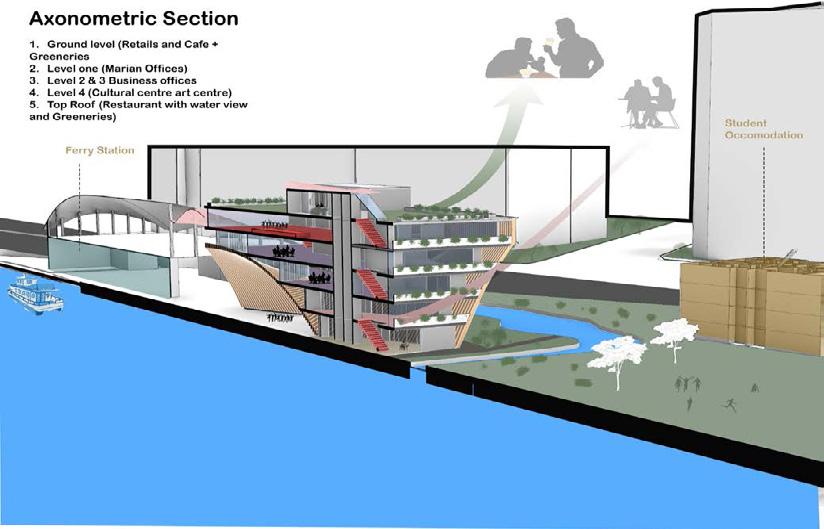
Figure 68 Ferry station iteration 03for Water-Front Intervention made By Jack Yalda, Collaborated by Goce Lazareski and Abdul Khaliq Shahab as part of ST1_Group 7 for WaterFront Intervention
Figure 70 Ferry station iteration 03for Water-Front Intervention made By Jack Yalda, Collaborated by Goce Lazareski and Abdul Khaliq Shahab as part of ST1_Group 7 for WaterFront Intervention
Figure 69 Ferry station iteration 03for Water-Front Intervention made By Jack Yalda, Collaborated by Goce Lazareski and Abdul Khaliq Shahab as part of ST1_Group 7 for WaterFront Intervention
Figure 71 Axonometric Section for Water-Front Intervention made By Abdul Khaliq Shahab, Collaborated by Goce Lazareski and Jack Yalda as part of ST1_Group 7 for WaterFront Intervention
PART C - From Form Finding to Water-front Placemaking (Design Development)
C4: Design Iterations
Concept Development
Iteration 04


Figure 72 Iteration 2 Water-Front Intervention made ByJack Yalda, Collaborated by Goce Lazareski and Abdul Khaliq Shahab, as part of ST1_Group 7 for WaterFront Intervention
Figure 73 Connection of Buildings for Water-Front Intervention made By Jack Yalda Collaborated by Abdul Khaliq Shahab and Goce Lazareski as part of ST1_Group 7 for WaterFront Intervention
Figure 74 Physical Iteration 4 Site Model 01 for Water-Front Intervention By Jack Yalda Collaborated by Goce Lazareski and Abdul Khaliq Shahab as part of ST1_Group 7 for WaterFront Intervention
PART C - From Form Finding to Water-front Placemaking (Design Development)
C4: Design Iterations
Concept Development
Iteration 05

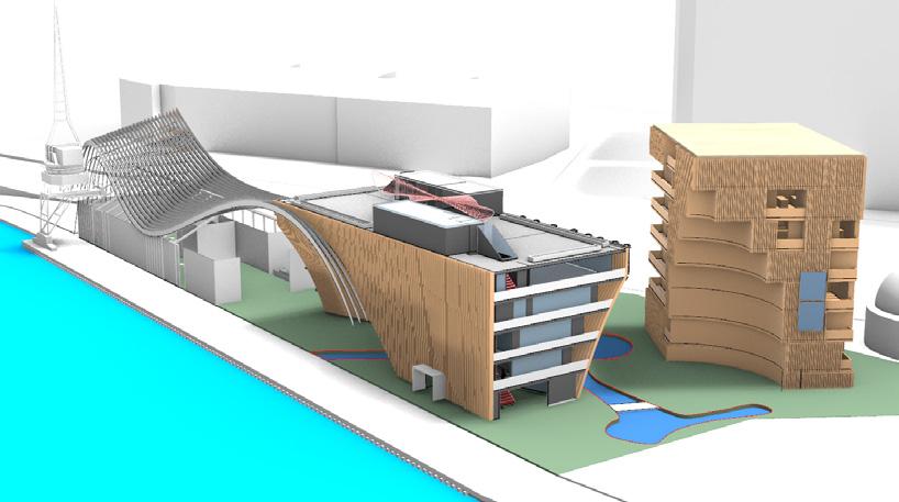

Figure 76 Site Plan for Water-Front Intervention made By Abdul Khaliq Shahab, Collaborated by Jack Yalda and Goce Lazareski as part of ST1_Group 7 for WaterFront Intervention
Figure 75 Connection of Buildings for Water-Front Intervention made By Jack Yalda Collaborated by Abdul Khaliq Shahab and Goce Lazareski as part of ST1_Group 7 for WaterFront Intervention
Figure 77 Connection of Buildings for Water-Front Intervention made By Jack Yalda Collaborated by Abdul Khaliq Shahab and Goce Lazareski as part of ST1_Group 7 for WaterFront Intervention
PART C - From Form Finding to Water-front Placemaking (Design
C4: Design Iterations
Concept Development
Conceptual Student Accommodation Plans


Part C5 - Before and After
Week 7-11
PART C - From Form Finding to Water-front Placemaking (Design Development)
C5: Before and After Site Plan
Concept Development
Concept Site Plan Before and After

Existing Site Plan
78 Site Plan Before l for Water-Front Intervention made By Jack Yalda, Collaborated by Goce Lazareski and Abdul Khaliq Shahab as part of ST1_Group 7 for WaterFront Intervention

Proposed After Site Plan
Figure 79 Site Plan Before l for Water-Front Intervention made By Jack Yalda, Collaborated by Goce Lazareski and Abdul Khaliq Shahab as part of ST1_Group 7 for WaterFront Intervention
Figure
Part C6 - Facade Design Iterations and Ideations
Week 7-11
PART C - From Form Finding to Water-front Placemaking (Design Development)
C6: Facade Design iterations and Ideations
Concept Development
Facade Design Iterations

Figure 80 Apartment Facade for Water-Front Intervention made By Abdul Khaliq Shahab, Collaborated by Goce Lazareski and Jack Yalda as part of ST1_Group 7 for WaterFront Intervention

Figure 82 Apartment Facade for Water-Front Intervention made By Goce Lazareski, Collaborated by and Abdul Khaliq Shahab and Jack Yalda as part of ST1_Group 7 for WaterFront Intervention

Figure 81 Apartment Facade for Water-Front Intervention made By Abdul Khaliq Shahab, Collaborated by Goce Lazareski and Jack Yalda as part of ST1_Group 7 for WaterFront Intervention

Figure 83 Shed Facade for Water-Front Intervention made By Abdul Khaliq Shahab, Collaborated by Goce Lazareski and Jack Yalda as part of ST1_Group 7 for WaterFront Intervention
PART C - From Form Finding to Water-front Placemaking (Design Development)
C6: Facade Design iterations and Ideations
Concept Development
Concept Student Accommodation Plans and Facade


Figure 84 Apartment Facade for Water-Front Intervention made By Abdul Khaliq Shahab, Collaborated by Goce Lazareski and Jack Yalda as part of ST1_Group 7 for WaterFront Intervention
PART C - From Form Finding to Water-front Placemaking (Design
C6: Facade Design iterations and Ideations
Concept Development
Concept Student Accommodation Plans and Final Facade

Figure 85 Apartment Facade for Water-Front Intervention made By Goce Lazareski, Collaborated by Abdul Khaliq Shahab and Jack Yalda as part of ST1_Group 7 for WaterFront Intervention
Part C7 - Reflection and Conclusion
Week 7-11
PART C - From Form Finding to Water-front Placemaking (Design Development)
C7: Reflection and Conclusion
Reflection and Conclusion
Reflection
Based on the feedback of the initial mid semester proposal and over the final 7 weeks of the semester our team were to further develop our design idea and work together on how we could better utilize the space and site while maintaining a unique architectural response and design while providing a space that was inviting for the students, this included moving some of our programs from the mixed use into the ferry station, converting the goods shed into a ferry station for people to go on tours and as a café for people to relax, removing the student accommodation and creating an individual building for it, This was developed through early schematic plans which included testing out various forms for the accommodation so that the existing façade connection continues onto the accommodation structure, testing out circulation and flow throughout the site and enhancing the connection. The concept development allowed me to test out ideas that weren’t successful as other ideas while also elevauating and adjusting my approach to the project.
PART D - Detailed Design and Tectonics
Detailed Designs and Tectonics
Week 7-11
Part D1 - Diagram Drawings
Week 7-11
PART D - Detailing & Tectonics
D1: Diagram Drawings
Detailed Design
Diagram Drawings


Figure 86 Proposed Site Plan for Water-Front Intervention made By Abdul Khaliq Shahab, Collaborated by Goce Lazareski and Jack Yalda as part of ST1_Group 7 for WaterFront Intervention
Figure 87 Bubble Diagram for Water-Front Intervention made By Abdul Khaliq Shahab, Collaborated by Goce Lazareski and Jack Yalda as part of ST1_Group 7 for WaterFront Intervention
PART D - Detailing & Tectonics
D1: Diagram Drawings
Detailed Design
Diagram Drawings

Figure 88 Overall circulation Diagram for Water-Front Intervention made By, Jack Yalda Collaborated by Goce Lazareski and Abdul Khaliq Shahab as part of ST1_Group 7 for WaterFront Intervention
PART D - Detailing & Tectonics
D1: Diagram Drawings
Detailed Design
Diagram Drawings


Figure 89 Circulation Diagram for Water-Front Intervention made By Abdul Khaliq Shahab, Collaborated by Goce Lazareski and Jack Yalda as part of ST1_ Group 7 for WaterFront Intervention
Figure 91 Proposed Site Plan for Water-Front Intervention made By Abdul Khaliq Shahab, Collaborated by Goce Lazareski and Jack Yalda as part of ST1_Group 7 for WaterFront Intervention
Figure 90 Cross Section Axonometric for Water-Front Intervention made By Abdul Khaliq Shahab, Collaborated by Goce Lazareski and Jack Yalda as part of ST1_Group 7 for WaterFront Intervention
Part D2 - Mixed Use Drawings
Week 7-11
PART D - Detailing & Tectonics
D2: Mixed Use Building Drawings
Detailed Design
Final mixed use drawings

By Abdul Khaliq Shahab, Collaborated by Goce Lazareski and Jack Yalda as part of ST1_Group 7 for WaterFront Intervention

By
Figure 92 Proposed level 1 mixed use floor Plan for Water-Front Intervention made
Figure 93 Proposed level 2 mixed use floor Plan for Water-Front Intervention made
Abdul Khaliq Shahab, Collaborated by Goce Lazareski and Jack Yalda as part of ST1_Group 7 for WaterFront Intervention
PART D - Detailing & Tectonics
D2: Mixed Use Building Drawings
Detailed Design
Final mixed use drawings

94 proposed level 3 mixed use floor Plan for Water-Front Intervention made By Abdul
Shahab, Collaborated by Goce Lazareski and Jack Yalda as part of ST1_Group 7 for WaterFront Intervention


Figure
Khaliq
Figure 95 Proposed level 5 mixed use floor Plan for Water-Front Intervention made By Abdul Khaliq Shahab, Collaborated by Goce Lazareski and Jack Yalda as part of ST1_Group 7 for WaterFront Intervention
Figure 96 proposed level 6 mixed use floor Plan for Water-Front Intervention made By Abdul Khaliq Shahab, Collaborated by Goce Lazareski and Jack Yalda as part of ST1_Group 7 for WaterFront Intervention
Part D3 - Ferry Station Final Drawings
Week 7-11
PART D - Detailing & Tectonics
D3: Ferry Station final Drawings
Detailed Design
Final ferry station drawings


Figure 97 Final Ferry station Floor Plan for Water-Front Intervention made By Jack Yalda Collaborated by Goce Lazareski and Abdul Khaliq Shahab as part of ST1_Group 7 for WaterFront Intervention
Figure 98 Final Ferry station sectional perspective for Water-Front Intervention made By Jack Yalda Collaborated by Goce Lazareski and Abdul Khaliq Shahab as part of ST1_Group 7 for WaterFront Intervention
Figure 99 Final Ferry station sectional perspective for Water-Front Intervention made By Jack Yalda Collaborated by Goce Lazareski and Abdul Khaliq Shahab as part of ST1_Group 7 for WaterFront Intervention
Part D4 - Final Student Accommdation Drawings
Week 7-11
PART D - Detailing & Tectonics
D4: Final Student Accommodation Drawings
Detailed Design
Final student accommodation plans
PART D - Detailing & Tectonics
D4: Final Student Accommodation Drawings
Detailed Design
Final student accommodation plans
PART D - Detailing & Tectonics
D4: Final Student Accommodation Drawings
Detailed Design
Final student accommodation plans
PART D - Detailing & Tectonics
D4: Final Student Accommodation Drawings
Detailed Design
Unit type Plans
PART D - Detailing & Tectonics
D4: Final Student Accommodation Drawings
Detailed Design
Axonometric Drawings/Perpsective Drawings
OCCUPANTS: UNIVERSITY STUDENTS, YOUNG PEOPLE LOOKING TO DOWNSIZE FLOORPLAN TYPE 1
AXONOMETRIC VIEW
APARTMENT 1: 2 BEDROOM APARMENT 94sqm
FLOORPLAN TYPE 2
PART D - Detailing & Tectonics
D4: Final Student Accommodation Drawings
Detailed Design
Sectional Perspective and Section Drawings
SECTIONAL VIEW
Figure_Sectional Layering Model
Figure_Sectional Perspective
Part D5 - Tectonics/Massing Models
Week 7-11
PART D - Detailing & Tectonics
D5: Tectonics/Massing Models
Detailed Design
Layering/massing Models

100 Layering/Massing Model for Water-Front Intervention made By Jack Yalda, Collaborated by Goce Lazareski and Abdul Khaliq Shahab as part of ST1_Group 7 for WaterFront Intervention


101 Layering/Massing Model for Water-Front Intervention made By Jack Yalda, Collaborated by Goce Lazareski and Abdul Khaliq
as part of ST1_Group 7 for WaterFront Intervention

Figure
Figure
Shahab
Figure 102 Layering/Massing Model for Water-Front Intervention made By Jack Yalda, Collaborated by Goce Lazareski and Abdul Khaliq Shahab as part of ST1_Group 7 for WaterFront Intervention
Figure 103 Sectional Model for Water-Front Intervention made By Jack Yalda, Collaborated by Goce Lazareski and Abdul Khaliq Shahab as part of ST1_Group 7 for WaterFront Intervention
PART D - Detailing & Tectonics
D5: Tectonics/Massing Models
Detailed Design
Layering/massing Models


Figure 104 Facade Detail Model for Water-Front Intervention made By Jack Yalda, Collaborated by Goce Lazareski and Abdul Khaliq Shahab as part of ST1_Group 7 for WaterFront Intervention
Figure 105 Facade Detail Model for Water-Front Intervention made By Jack Yalda, Collaborated by Goce Lazareski and Abdul Khaliq Shahab as part of ST1_Group 7 for WaterFront Intervention
Figure 106 Facade Detail Model for Water-Front Intervention made By Jack Yalda, Collaborated by Goce Lazareski and Abdul Khaliq Shahab as part of ST1_Group 7 for WaterFront Intervention
PART D - Detailing & Tectonics
D5: Tectonics/Massing Models
Detailed Design
Apartment Phyiscal Model and Site Plan


Figure 107 Proposed Site Model for Water-Front Intervention made By Jack Yalda, Collaborated by Goce Lazareski and Abdul Khaliq Shahab as part of ST1_Group 7 for WaterFront Intervention
Part D6 - Facade Detail Drawings
Week 7-11
PART D - Detailing & Tectonics
D6: Facade Detail Drawings
Detailed Design
Facade Detail Drawing


Figure 109 Facade Isometric Cut away detail for Water-Front Intervention made By Abdul Khaliq Shahab, Collaborated by Jack Yalda and Goce Lazareski as part of ST1_Group 7 for WaterFront Intervention
Figure 108 Facade Isometric Cut away detail for Water-Front Intervention made By Abdul Khaliq Shahab, Collaborated by Jack Yalda and Goce Lazareski as part of ST1_Group 7 for WaterFront Intervention
Figure 110 Facade Partial Section for Water-Front Intervention made By Abdul Khaliq Shahab, Collaborated by Jack Yalda and Goce Lazareski as part of ST1_Group 7 for WaterFront Intervention
PART D - Detailing & Tectonics
D6: Facade Detail Drawings
Detailed Design
Apartment Facade detail Drawing:
Timber Batten Detail scale 1:20
Part D6 - Final before and after master-plan Week 7-11
PART D - Detailing & Tectonics
D6: Final Before and After Master-Plan
Detailed Design
Final Before and After Masterplan

Existing Site Plan
Figure 111 Existing Site Plan for Water-Front Intervention made By Jack Yalda, Collaborated by Abdul Khaliq Shahab and Goce Lazareski as part of ST1_Group 7 for WaterFront Intervention

Proposed After Site Plan
Figure 112 Proposed Site Plan for Water-Front Intervention made By Jack Yalda, Collaborated by Abdul Khaliq Shahab and Goce Lazareski as part of ST1_Group 7 for WaterFront Intervention
Part D7 - Renders and Key Moments
Week 7-11
PART D - Detailing & Tectonics
D7: Render/Key Moments
Detailed Design
Hero Shot Images of Project/Key Moments
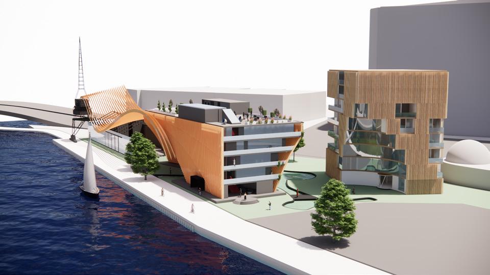


Figure 113 Perpsective Hero Shot 1 for Water-Front Intervention made By Abdul Khaliq Shahab, Collaborated by Goce Lazareski and Jack Yalda as part of ST1_Group 7 for WaterFront Intervention
Figure 114 Perpsective Hero Shot 2 for Water-Front Intervention made By Abdul Khaliq Shahab, Collaborated by Goce Lazareski and Jack Yalda as part of ST1_Group 7 for WaterFront Intervention
Figure 115 Perpsective Hero Shot 3 for Water-Front Intervention made By Abdul Khaliq Shahab, Collaborated by Goce Lazareski and Jack Yalda as part of ST1_Group 7 for WaterFront Intervention
Figure 116 Perpsective Hero Shot 4 for Water-Front Intervention made By Abdul Khaliq Shahab, Collaborated by Goce Lazareski and Jack Yalda as part of ST1_Group 7 for WaterFront Intervention
PART D - Detailing & Tectonics
D7: Render/Key Moments
Detailed Design


Figure 117 Perpsective Hero Shot 5 for Water-Front Intervention made By Abdul Khaliq Shahab, Collaborated by Goce Lazareski and Jack Yalda as part of ST1_Group 7 for WaterFront Intervention
Figure 118 Perpsective Hero Shot 3 for Water-Front Intervention made by Abdul Khaliq Shahab, Collaborated by Goce Lazareski and Jack Yalda as part of ST1_Group 7 for WaterFront Intervention
Figure 119 Perpsective Hero Shot 7 for Water-Front Intervention made By Abdul Khaliq Shahab, Collaborated by Goce Lazareski and Jack Yalda as part of ST1_Group 7 for WaterFront Intervention
Hero Shot Images of Project/Key Moments
PART D - Detailing & Tectonics
D7: Render/Key Moments
Detailed Design
Interior Shots of Project/Key Moments


Figure 120 Apartment bedroom Interior Render for Water-Front Intervention made By Goce Lazareski, Collaborated by Jack Yalda and Abdul Khaliq Shahab as part of ST1_Group 7 for WaterFront Intervention
Figure 121 Living Room Interior Render for Water-Front Intervention made By Goce Lazareski, Collaborated by Jack Yalda and Abdul Khaliq Shahab as part of ST1_Group 7 for WaterFront Intervention
Figure 122 Ferry Station External Render for Water-Front Intervention made By Jack Yalda, Collaborated by Goce Lazareski and Abdul Khaliq Shahab as part of ST1_Group 7 for WaterFront Intervention
Figure 123 Ferry Station External Render for Water-Front Intervention made By Jack Yalda, Collaborated by Goce Lazareski and Abdul Khaliq Shahab as part of ST1_Group 7 for WaterFront Intervention
PART D - Detailing & Tectonics
D7: Render/Key Moments
Detailed Design
Interior Shots of Project/Key Moments

Figure_Reception/Lobby Area Interior Render by Goce Lazareski
Part D8 - Conclusion and Reflection
Week 7-11
PART D - Detailing & Tectonics
D8: Conclusion and Reflection
Detailed Design
Conclusion and Reference
Our team of Jack Yalda, and Abdul Khaliq Shahab and myself began this journey of creating our unique architectural response and design through research and analysis to gain a deeper understanding of the form created from our form finding machine, once we found this we investigated the various iterations that we could undertake to create a building form out of it, this understanding subsequent research helped us develop our concept through a variety of methods such as physical and massing models which helped shape our understanding of how the building sits within the surrounds and how it reacts and feedback gained throughout brought us to Dream-Time Yarra Living that we believe would be capable in creating and opening up Dockland’s vision of attraction and experience.
Throughout the design development this project has taught me a better understanding of how a design can be shaped by its surrounding contexts and historical issues while creating a unique response while investigating how the various forms help shape a structure.
Part D9 - Refernces
Week 7-11
NYC WORLD TRADE CENTER TRANSPORTATION HUB (THE OCULUS)
Pires, S� (2021, May 10)� 10 gravity-defying structures by Santiago Calatrava, legendary architect and Engineer� My Modern Met� https:// mymodernmet�com/santiago-calatrava-buildings/
Example of Form finding in Architecture
Hnin, T. (2023, December 15). An introductory guide to form-finding in Architecture (2024). Novatr Prev OX. https://www.novatr.com/blog/formfinding-in-architecture
Seattle Central Library
Pires, S� (2021, May 10)� 10 gravity-defying structures by Santiago Calatrava, legendary architect and Engineer� My Modern Met� https:// mymodernmet�com/santiago-calatrava-buildings/
Hnin, T. (2023, December 15). An introductory guide to form-finding in Architecture (2024). Novatr Prev OX. https://www.novatr.com/blog/formfinding-in-architecture
How tensile structures are revolutionizing the architecture industry? (n�d�)� https://parametric-architecture�com/how-tensile-structures-arerevolutionizing-the-architecture-industry/
Cordless Drill� Hire Pro� (2024, January 12)� https://hireproonline�com�au/product/cordless-drill/
Superlabelstore� (2022, February 9)� Types of stretch fabric� https://superlabelstore�com/blog/types-of-stretch-fabric/
3MM 1/8” x 12 x 12 Baltic birch plywood - b/BB grade, package of 6� Amazon�com�au: Toys & Games� (n�d�)� https://www�amazon�com�au/3MM-12Baltic-Birch-Plywood/dp/B07CHX1GTD?th=1
Clear acrylic sheet: Perspex sydney� KF Plastics� (2024, February 5)� https://www�kfplastics�com�au/plastic-sheets/clear-acrylic-sheet
Various classifications for architectural form finding process. (n.d.). https://eijest.journals.ekb.eg/ article_144055_29753df002bca04c4580ab33683f2114�pdf
Architectural forming between form making and form finding towards form ... (n.d.-a). https://www.jaes.journals.ekb.eg/ article_19243_6df2a35a34e4f93af40c1cfeed0f8391�pdf
Zaha Hadid architects� KnitCandela – Zaha Hadid Architects� (n�d�)� https://www�zaha-hadid�com/design/knitcandela/
Pires, S� (2021, May 10)� 10 gravity-defying structures by Santiago Calatrava, legendary architect and Engineer� My Modern Met� https://mymodernmet� com/santiago-calatrava-buildings/
Hnin, T. (2023, December 15). An introductory guide to form-finding in Architecture (2024). Novatr Prev OX. https://www.novatr.com/blog/form-findingin-architecture
A bold circular bridge defines waterfront art gallery in Nanchang. Azure Magazine. (2019, June 6). https://www.azuremagazine.com/article/bold-circularbridge-defines-waterfront-art-gallery-nanchang/
Network, L� L� A� (2015, April 30)� Giles Rayner and his mind bending water sculptures� Land8� https://land8�com/giles-rayner-and-his-mind-bendingwater-sculptures/
In!, C� M � (n�d�)� Architecture design #1 - cable tensile structure� Parametric House� https://parametrichouse�com/architecture-design-1-2/
ArchDaily� (n�d�)� https://www�archdaily�com/907733/waterfront-art-gallery-lacime-architects/5c139bc708a5e54bad000d1f-waterfront-art-gallerylacime-architects-photo?next_project=no
The healing power of water features - rock n water landscapes� Rock N Water Landscapes - Contact us today at 612-865-4504� (2018, January 24)� https://rocknwaterlandscapes�com/the-healing-power-of-water-features/
Trickling water fall fountains at best price in Delhi - ID: 4370845: DANTECH Technologies� at Best Price in Delhi - ID: 4370845 | DANTECH TECHNOLOGIES� (n�d�)� https://www�exportersindia�com/product-detail/trickling-water-fall-fountains-4370845�htm
ArchDaily� (n�d�)� https://www�archdaily�com/907733/waterfront-art-gallery-lacime-architects/5c139bc708a5e54bad000d1f-waterfront-art-gallerylacime-architects-photo?next_project=no
The Benefits of using Greening Urban Spaces Penso. (2022, March 19). The benefits of “greening” urban spaces - programmed au: The power of a job done right. Programmed AU | The Power of a Job done Right. https://programmed.com.au/the-benefits-of-greening-urban-spaces/
PARKROYAL Collection Pickering incorporates the tropical climate of Singapore into the building� iStock Editorial/Getty Images
Example of Water Integration with Buildings Cao, L� (2020, January 1)� Innovative uses of water in architecture� ArchDaily� https://www�archdaily� com/931070/innovative-uses-of-water-in-architecture
Condominium entrance, entrance design, facade architecture� Pinterest� (2017, August 25)� https://www�pinterest�com�au/pin/325103666843271901/
Landfair Apartments� Neutra Institute for Survival Through Design� (2024, February 1)� https://neutra�org/project/landfair-apartments-ucla-co-opstudent-housing/
Lizzie Crook | 7 January 2021 Leave a comment. (2021, January 8). Zaha Hadid architects designs student housing with rooftop walkway in Hong Kong. Dezeen� https://www�dezeen�com/2021/01/07/zaha-hadid-architects-student-residence-development-at-hkust/
Zaha Hadid architects� Jockey Club i-Village at Hong Kong University of Science and Technology (HKUST) – Zaha Hadid Architects� (n�d�)� https://www� zaha-hadid�com/architecture/student-residence-development-at-hong-kong-university-of-science-and-technology-hkust/
Harrouk, C� (2021, January 6)� Zaha Hadid architects designs student residence development at the Hong Kong University of Science and Technology� ArchDaily� https://www�archdaily�com/954470/zaha-hadid-architects-designs-student-residence-development-at-the-hong-kong-university-of-scienceand-technology
Yeoui-Naru Ferry Terminal� Luca Poian Forms� (2023, May 23)� https://www�lucapoianforms�com/projects/yeoui-naru-ferry-terminal/?fbclid=IwZXh 0bgNhZW0CMTAAAR2N-KM70l6xe6l2FhMmUOOZ6wnutl_ZgE7M-nQLF2JC5HqLwyakZQUGTRM_aem_AWhEpCsC1fm-WwSUeF06IHotYmCp1P6NkXm7EJl9jySPWqfCz7nGmUx-jm6vgjWd2hCEdQyebYHwCSpnnAFzls6