GLORIA, POU WAI, LEI
Portfolio 2024

Portfolio 2024
My work revolves around three interrelated concepts - interaction, computation, and materialisation.
[ Interaction ] points to the act of communication and negotiation between three players - the environment, the architectural components, and the human agents. For me, interaction design is about determining the mechanisms and interfaces that govern the type of exchanges between these players and how they are to take place.
[ Computation ] is about the act of interpreting, processing, and operating on data gathered from the interaction events. In this context, computation design is about determining the patterns, logic, rules, and algorithms to be implemented. It involves defining how ‘element A’ will relate to ‘element B’ and creating the necessary arrangements to connect the two accordingly.
[ Materialisation ] is the translation of the abstract relationships and intentions generated from the interactive and computational design into a series of spatial, formal, and physical manifestations.
The projects presented in the ‘Personal’ section are selected to highlight explorations of these three concepts in different contexts and mediums. They cover a range of time periods in my personal development, illustrating how my idea of interaction, computation, and materialisation has evolved over time.
The works showcased in the ‘Practice-Led’ section represent key moments of my journey in the industry, covering projects from RIBA Stage 1 to 5 and scales ranging from interior design to urban planning.
PERSONAL >>
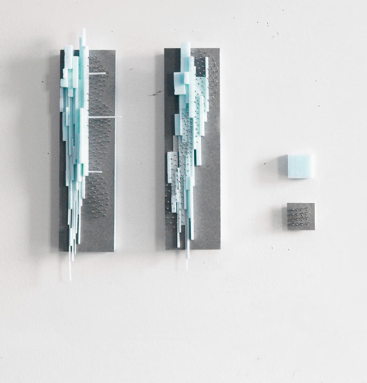
THE SALON THE SECRET LIFE OF YOUR WALLS
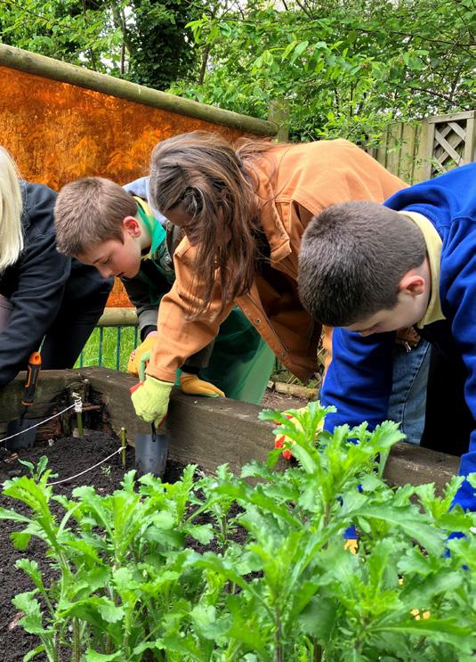
PRODUCTIVE GARDEN
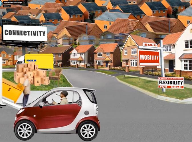
QUANTAMIC HOUSE
HUMANORAMA
SUN CATCHER
WATER AUTOMATON
PRACTICE-LED >>
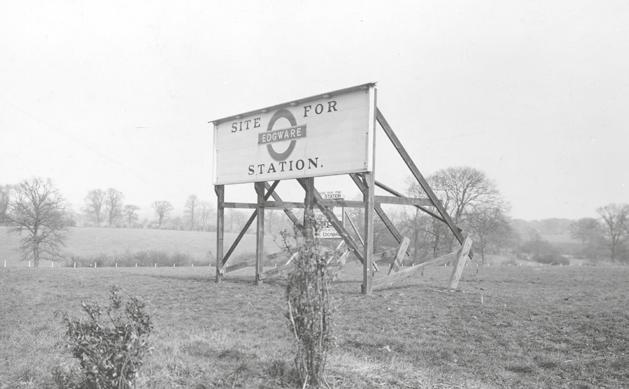
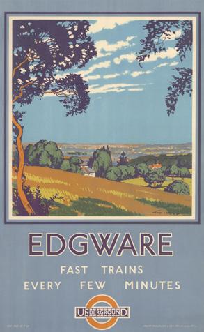
EDGWARE CENTRAL
STRATFORD WATERFRONT HOME 001
STEELES WEST
29 GREAT PETER STREET
CURRICULUM VITAEThe Bartlett School of Architecture, UCL, UK
PG Dip. in Professional Practice & Management in Architecture (ARB/RIBA Part III) (2016 - 2017)
Architectural Association (AA), School of Architecture, UK
AA Diploma (ARB/RIBA Part I & II) (2011 - 2014)
University of Waterloo, Canada
Bachelor of Architectural Studies (with Distinction), with Joint Honours in Philosophy (2004 - 2010)
CAD
Revit, ArchiCAD, AutoCAD, Vectorworks
3D Modelling & Prototyping
Rhinoceros, Grasshopper 3D, Arduino, Processing
Graphic
Adobe (Photoshop, Illustrator, InDesign), Procreate
Animation & Film Making
Cinema 4D, Adobe (After Effects)
General
Microsoft Office (Word, Excel, Power Point)
Language
English, Chinese (Cantonese, Mandarian)
RIBA Student Mentor, Central St Martin, 2018 & 2021
“What Do you See?” AArchitecture, no.22. (Eassy), 2014
ARCHITECT (RIBA / ARB)
www.gpwlei.co.uk
Howells (Glenn Howells Architects) Senior Architect | London, UK | 2022 - 2024
Edgware Town Centre Masterplan | Project Lead
London, UK, 4000 homes Mixed Use Masterplan, Stage 1 - 2, £1 billion
Stratford Waterfront | Senior Architect
London, UK, 700 homes Mixed Use Development, Stage 2, £250 million
Harper Downie Architects (HdAr)
Associate (2019-2022), Architect (2017-2019) | London, UK | 2014 - 2022
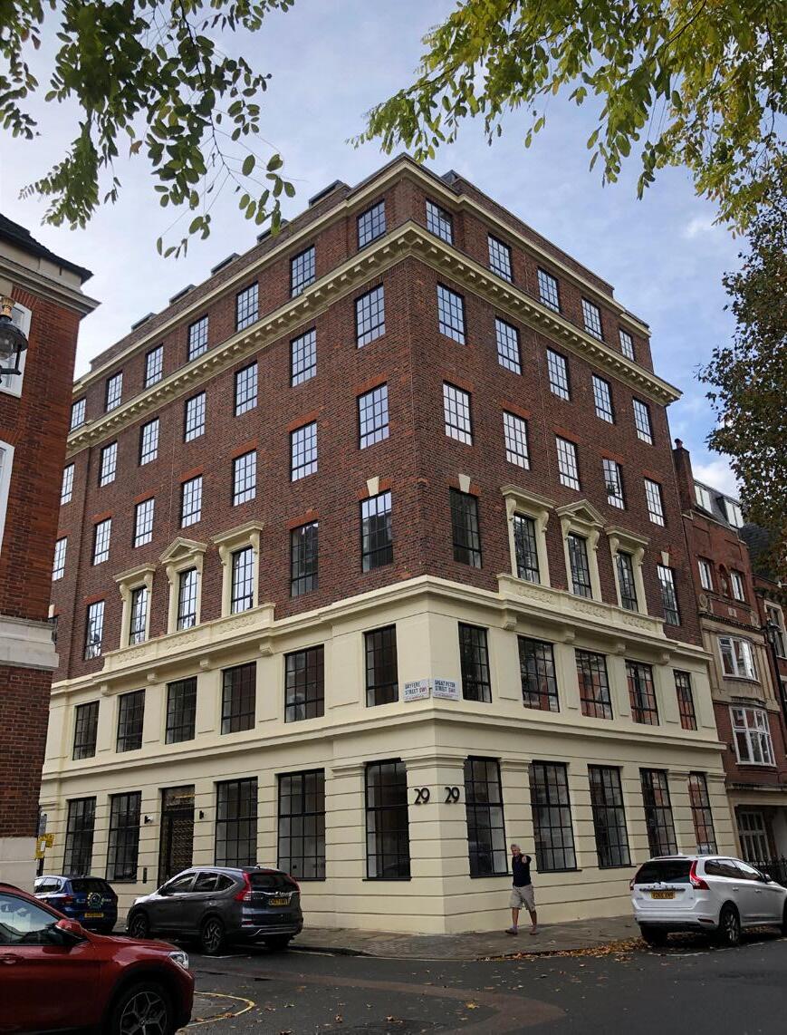
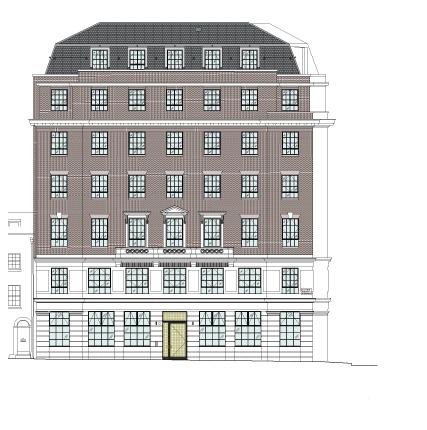
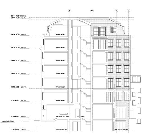
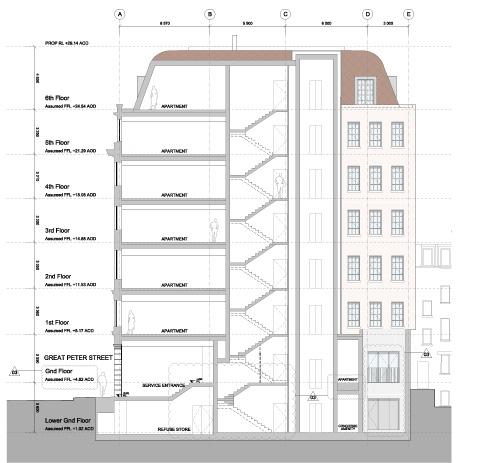
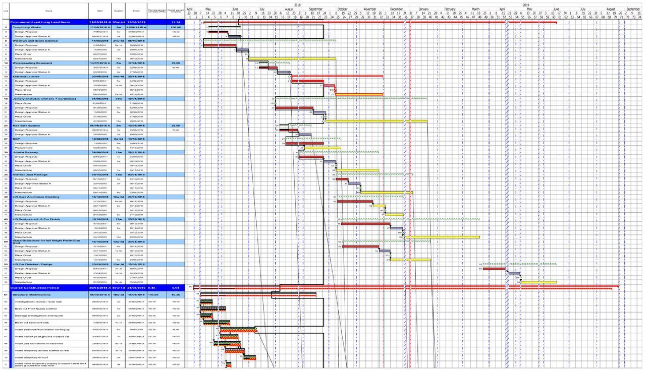
29 Great Peter Street | Project Manager, Project Architect, CA
London, UK, High-end Residential Development, Stage 3 to 6, £6.6 million
Manor Mews | Architect, CA
London, UK, Residential Development, Stage 4 to 5, £1.4 million
St James Church | Architect London, UK, Institution, Stage 2 to 3, £500k
24-49 Willow Way | Architect London, UK, Residential Development, Stage 0-1
Chitra Chalet | Architect Gastaad, Switzerland, Mix-Use Development, Stage 4, £2 million
Fann Street | Part II
Dr. Paul Thagard, University of Waterloo Research Assistant | Waterloo, Canada | 2010
Jiakun Architects Architectural Intern | Chengdu, China | 2008
Hangzhou Wetland Art Quarter | Intern Hangzhou, China, Culture & Hospitality, Design Development
Charles Gagnon Building Workshop (CARGO) Architectural Intern | Toronto, Canada | 2007
K.House | Intern
Quebec, Canada, Private Residential, Concept Design to Design Development
Bing Thom Architects (Revery)
Architectural Intern | Vancouver, Canada | 2006
London, UK, Residential Development, Stage 4 to 5, £12 million NBBJ
Stevens Group Architects (IBI Group)
Architectural Intern | Toronto, Canada | 2010 - 2011
Steeles West (Pioneer Village) Subway & Bus Station | Intern Toronto, CA, Transportation Infrastructure, Technical Design, $ 145 million CAD
Sheppard East Subway, Bus, & LRT Station | Intern Toronto, CA, Transportation Infrastructure, Concept Design
SAIT Polytechnic Campus | Intern Calgary, Canada, Education & Institution, Master Planning, $92 million (CAD)
Architectural Intern | NYC, US | 2006
Massachusetts General Hospital | Intern Boston, US, Healthcare, Schematic Design

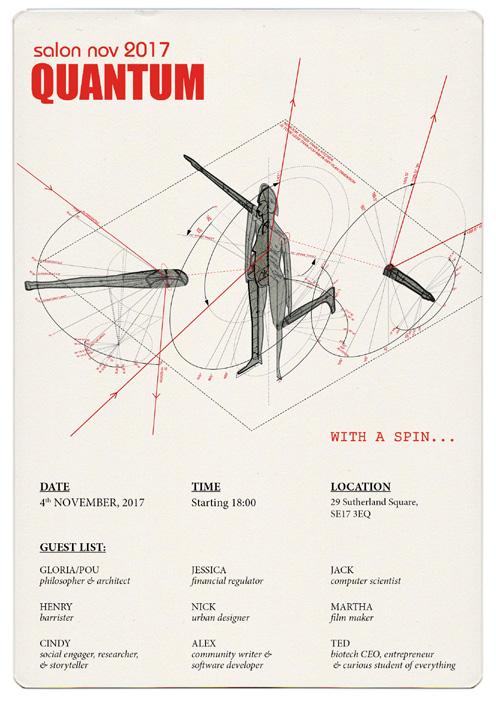

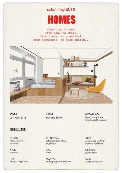

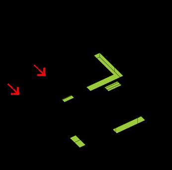
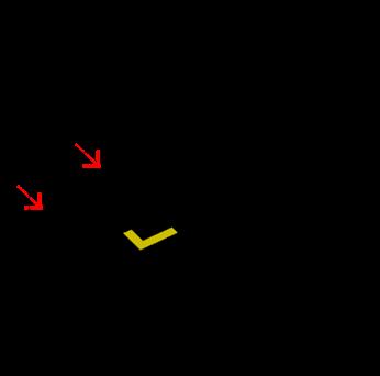
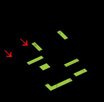
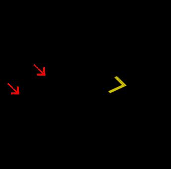
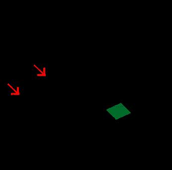
1 DINNER
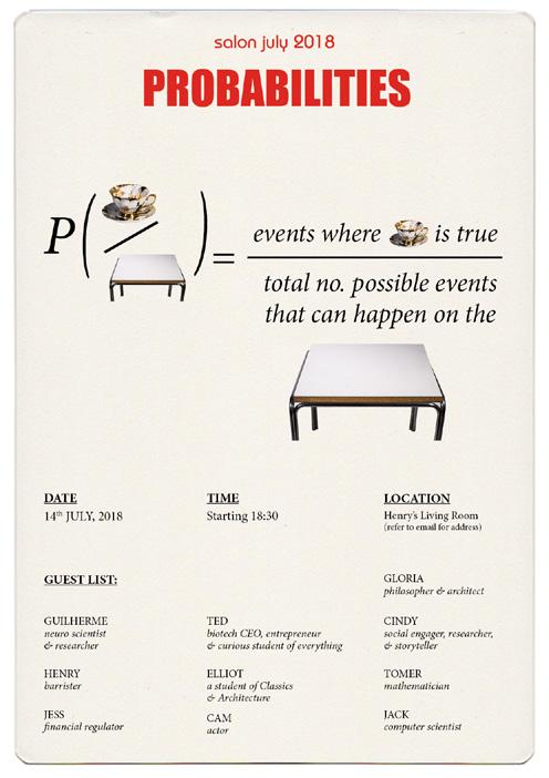
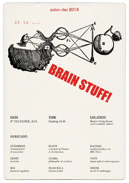
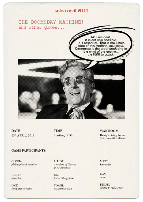
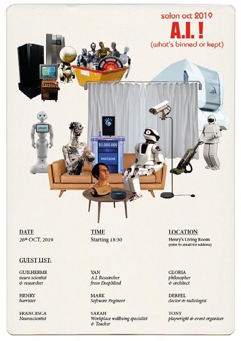
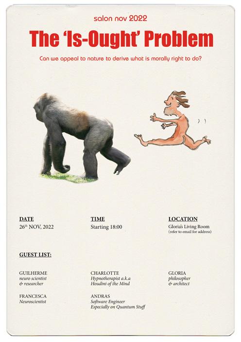
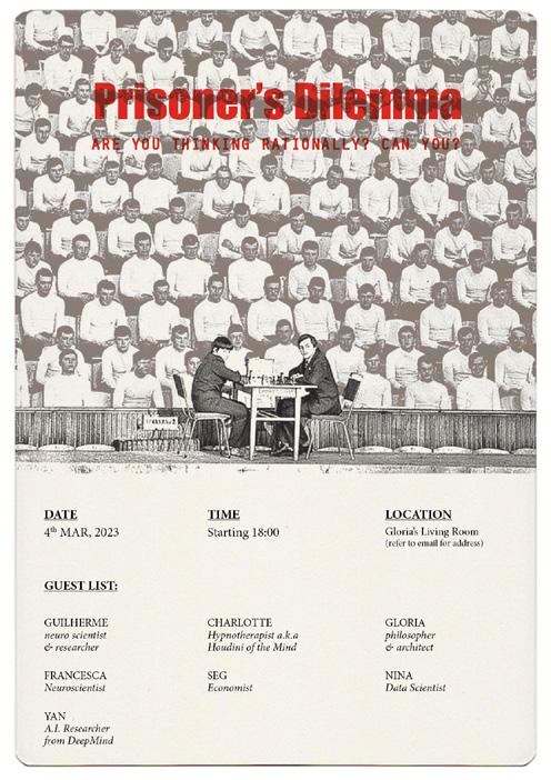
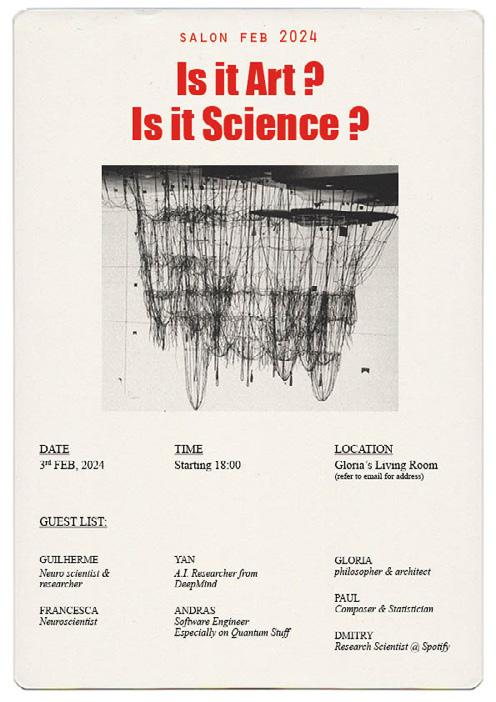
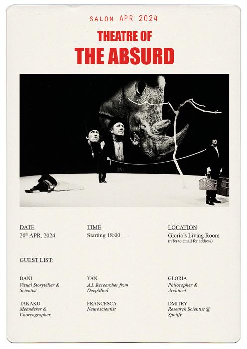
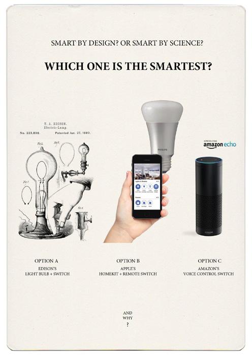
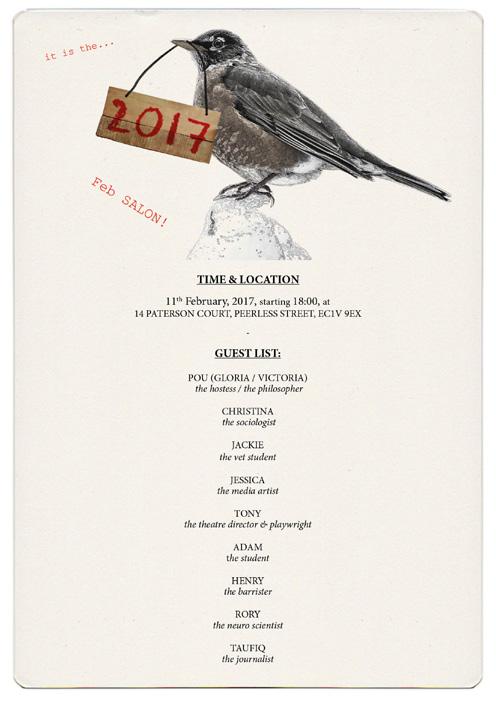
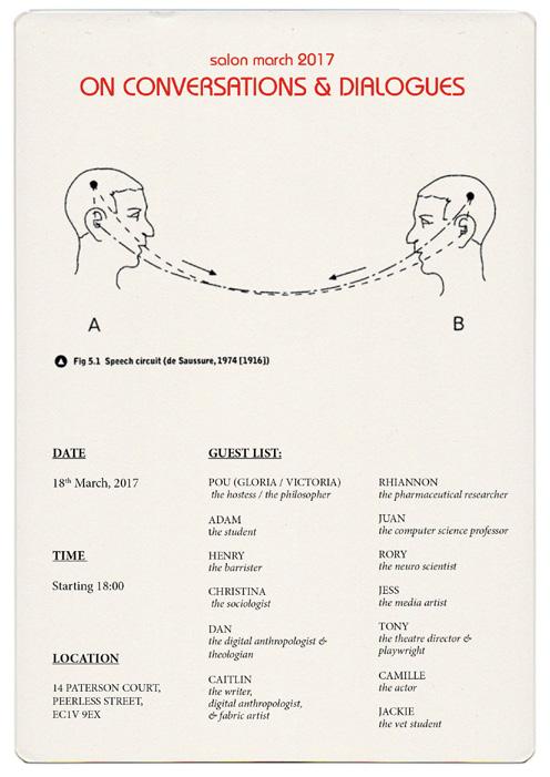
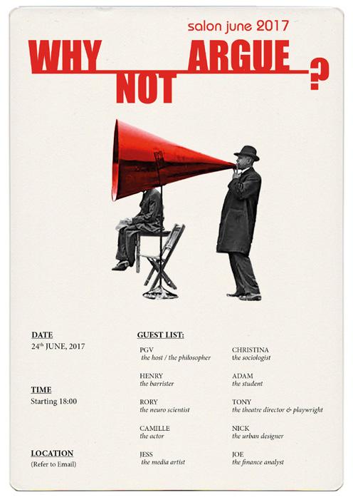
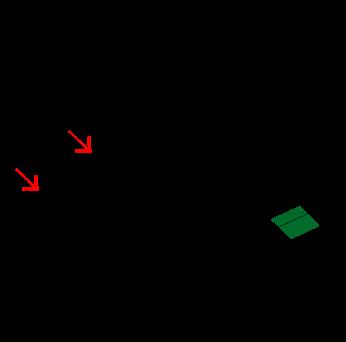
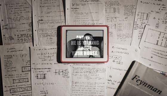
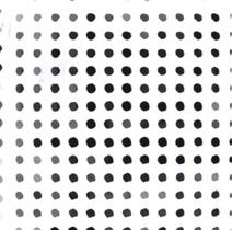
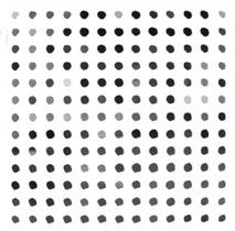
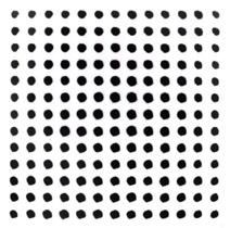
We may live in a world of unprecedented connectivity to an unlimited amount of information and news. However, that does not automatically equate to human connectivity. The question is how do we build bridges between the increasingly diverging branches of specialist knowledge to avoid ideological and intellectual echo chambers? To contribute in my own small way to generate crossdisciplinary interactions and to encourage mutual learning through conversations, I have started a quarterly private salon event. The ingredients are quite simple: six guests, one topic, one living room, over a dinner. As the host, my role is to come up with the topic, carefully curate the guest
to ensure
the event. The
and viewpoints, then, give
for
all kinds of events I have attended over the years, covering people from scientists, researchers, engineers, artists, to students. To date, 16 dinners have taken place. The above showcases the event posters that were included in the
and the
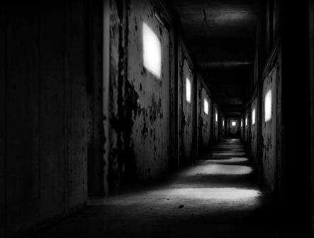
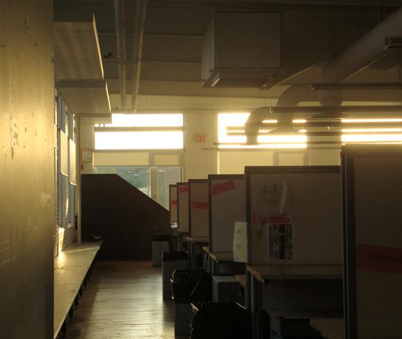
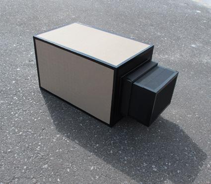
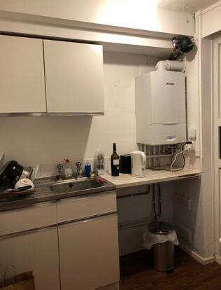
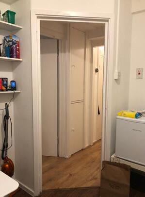
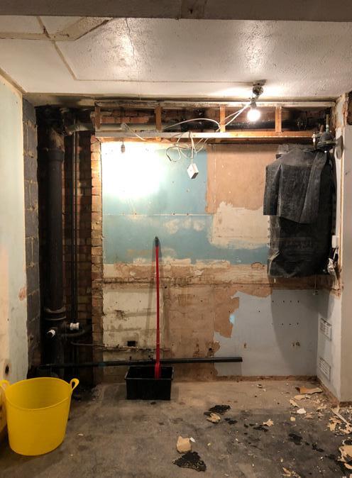
‘As I walked slowly around the empty lounge, feeling the walls angle and edge away, doorways widen when I approached, curious echoes stirred through the memories embedded in the house. The responses were undefined, but somehow eerie and unsettling, like being continually watched over one’s shoulder, each room adjusting itself to my soft, random footsteps as if they obtained the possibility of some explosive burst of temperament.’
- J.G. Ballard, Vermilion Sands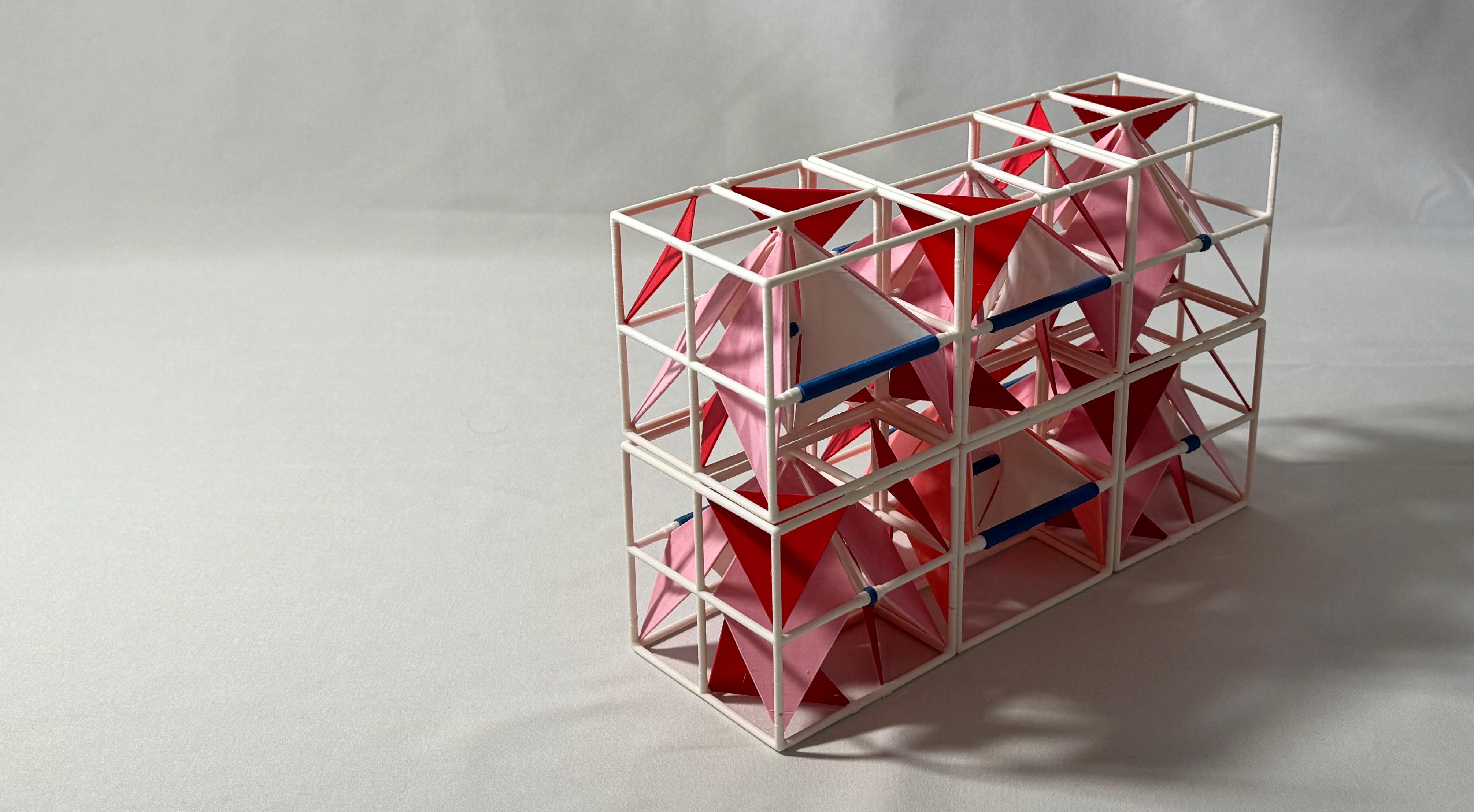
2024 - CURRENT PRIVATE RESEARCH
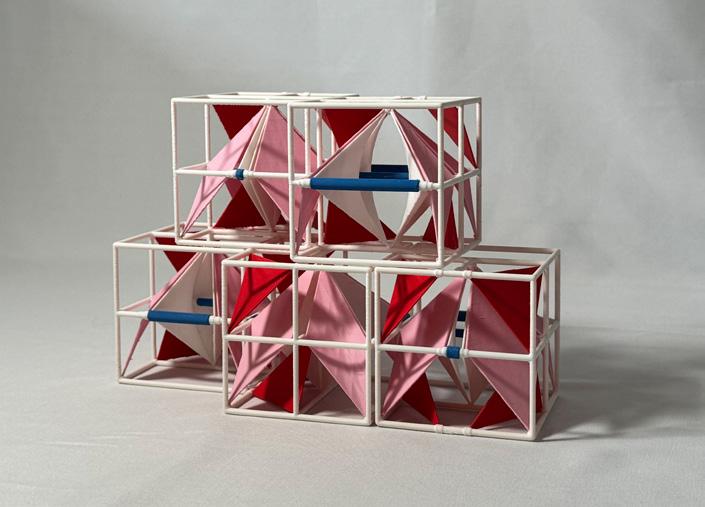
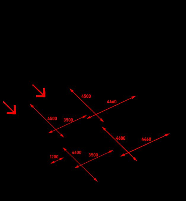
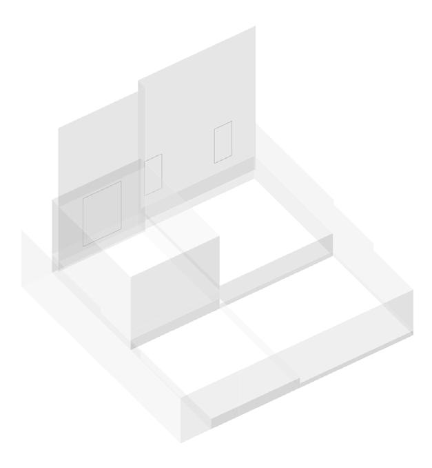
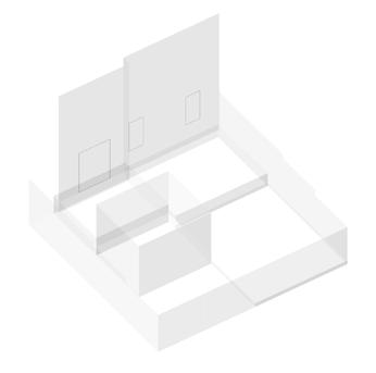
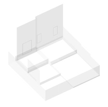
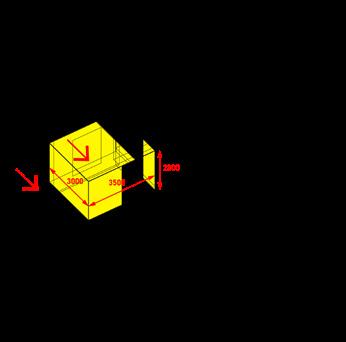
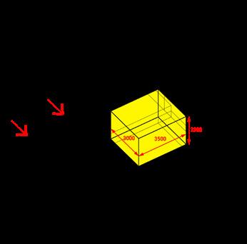
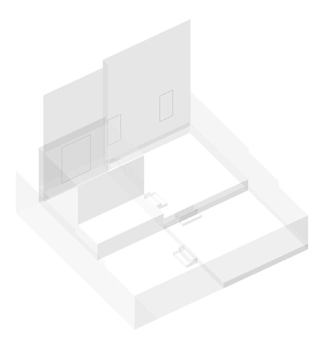
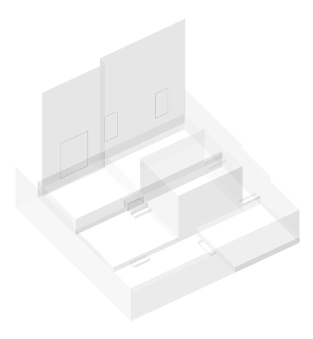
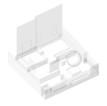
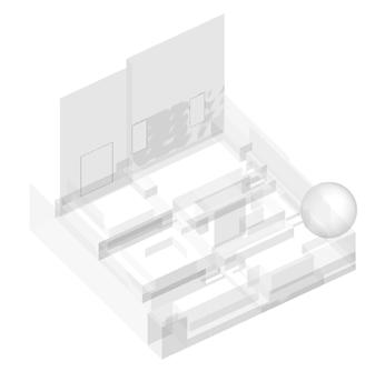
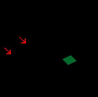
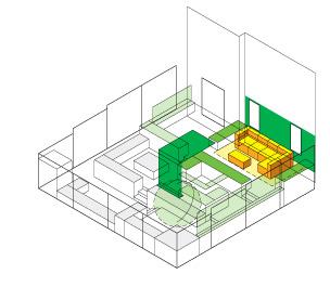
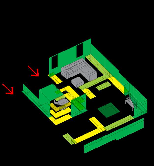
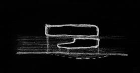
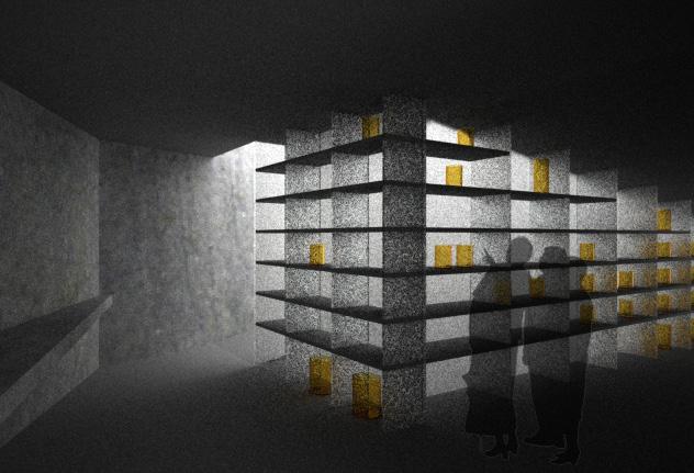
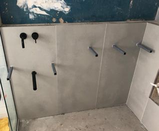
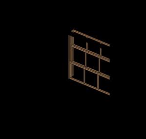
Focusing on the walls of our built environment as the site of investigation, this research is about reimagining the composition, functionality, modular formulation, and behaviour of an alternative wall system.
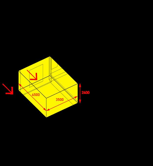
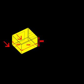
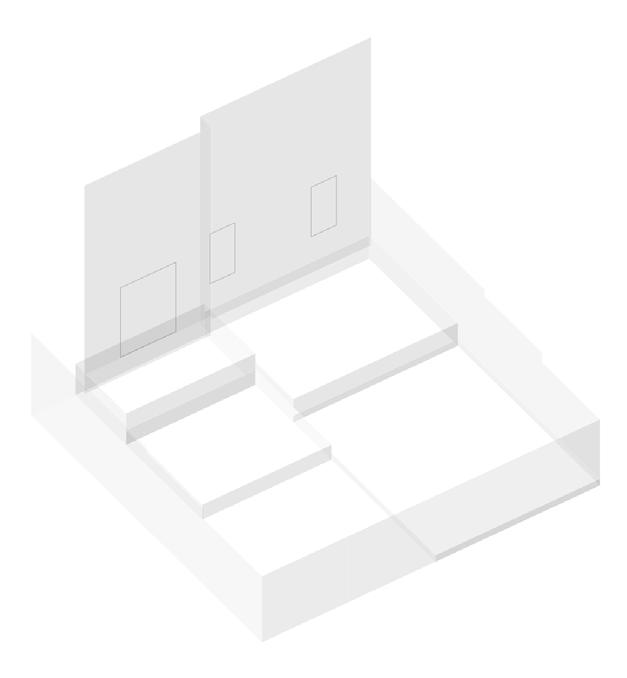
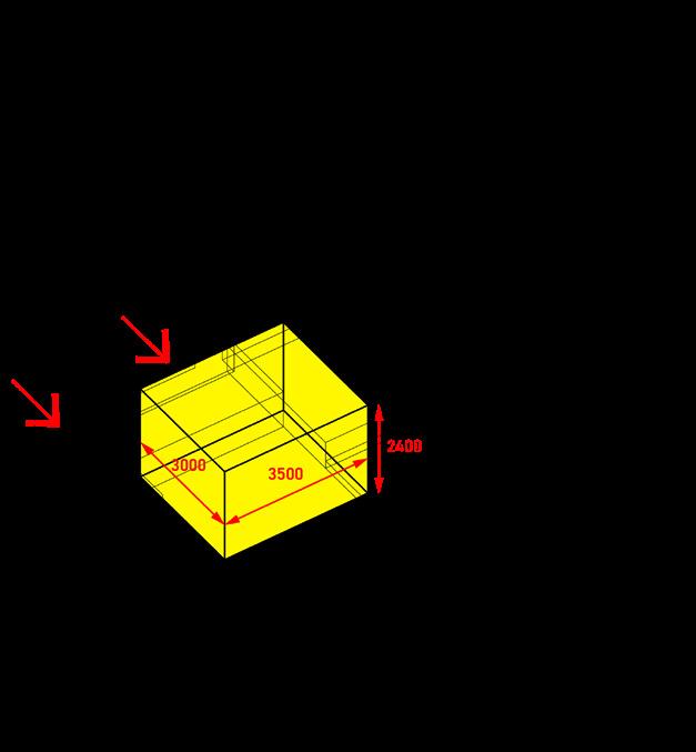
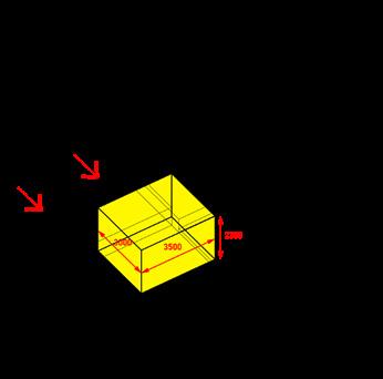
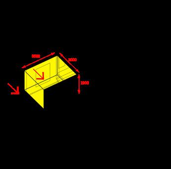
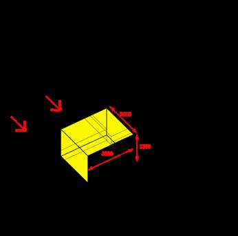
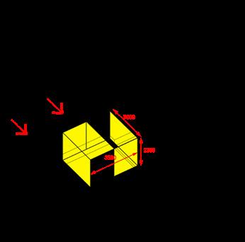
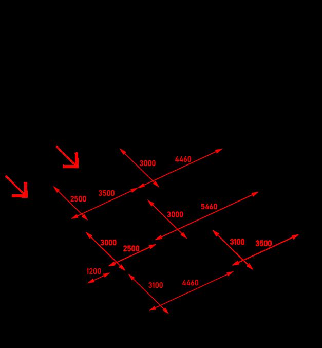
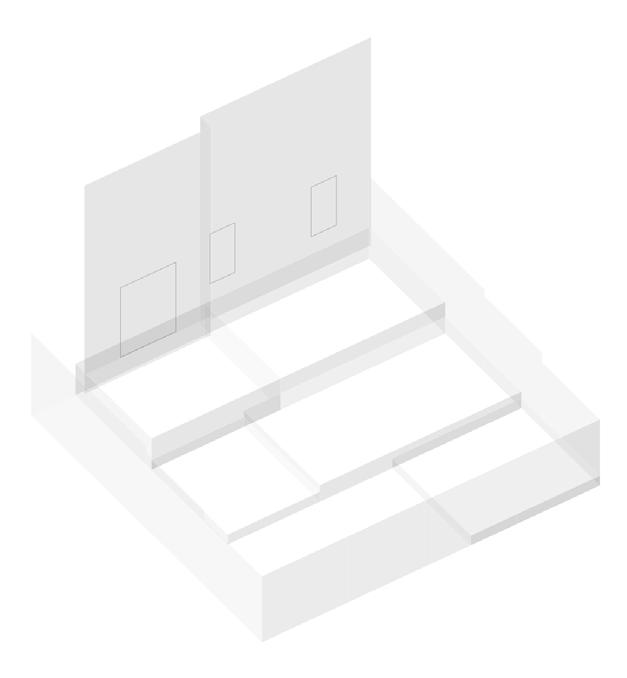
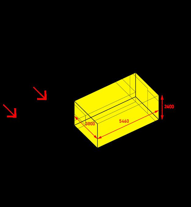
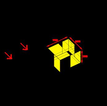
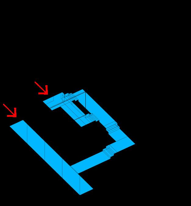
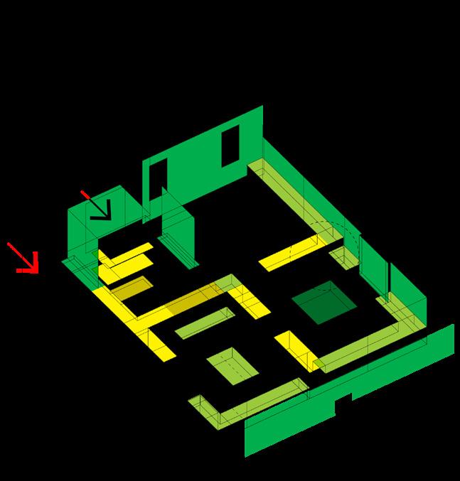
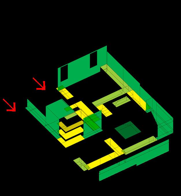
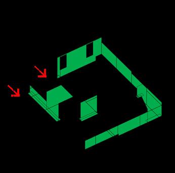
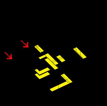
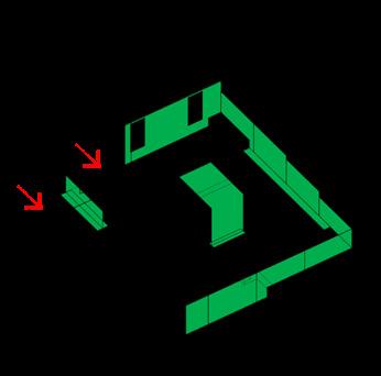
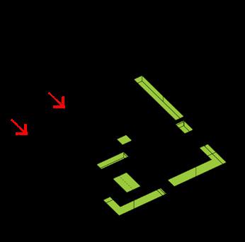
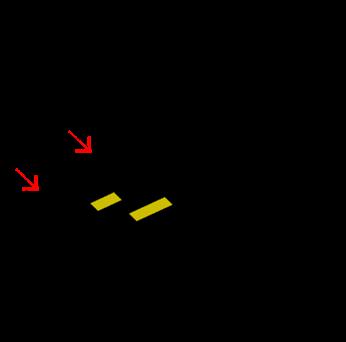
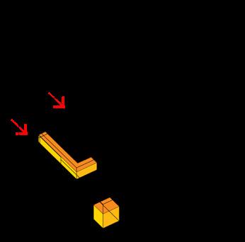
Define base wall dimension and module size
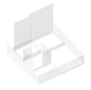
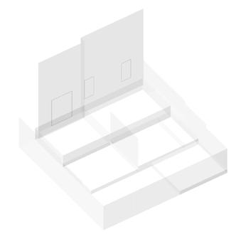
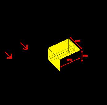
Program in site and user specific adaptations
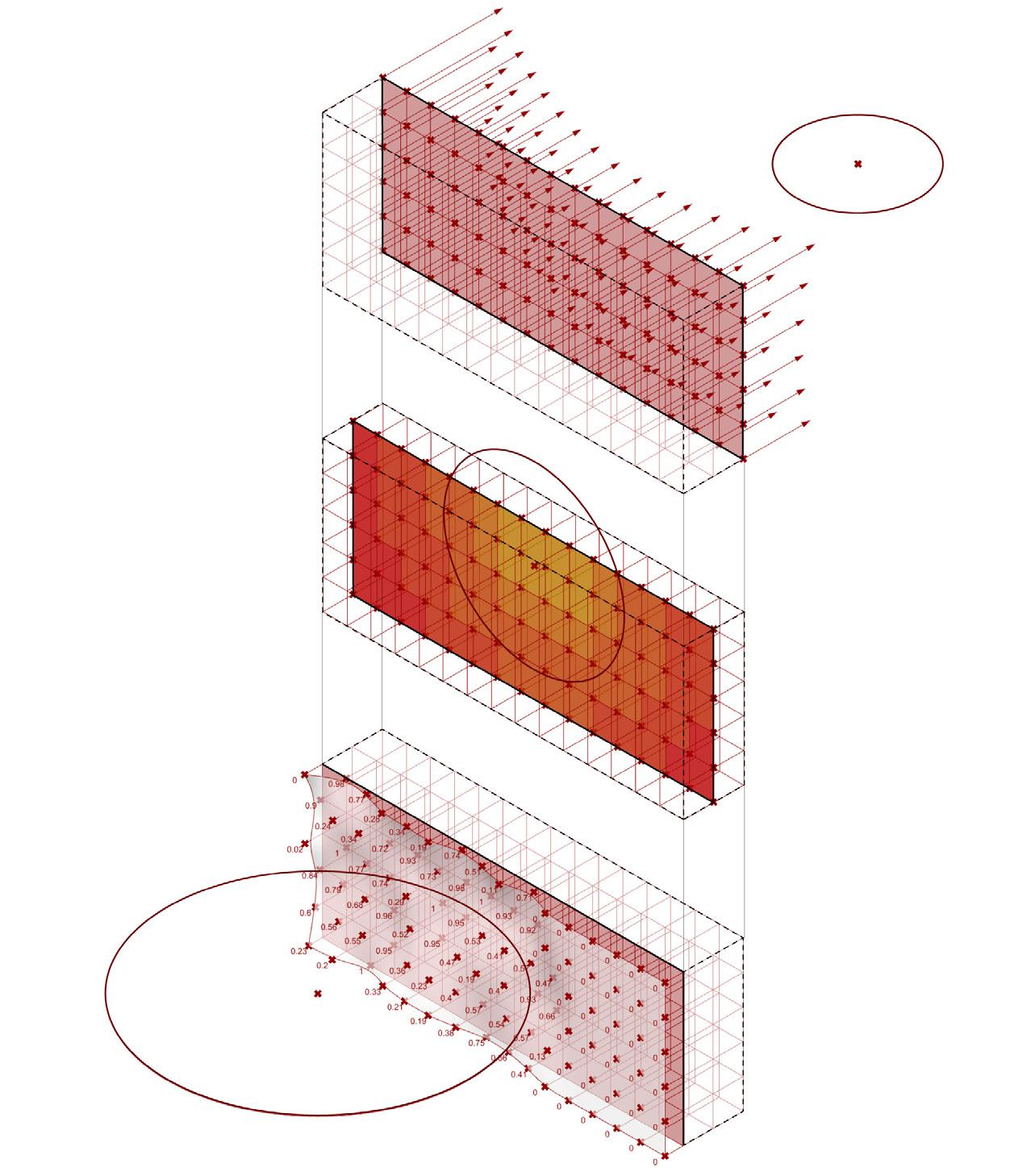
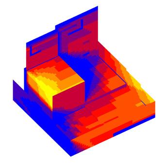
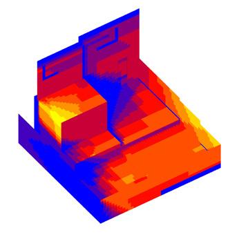
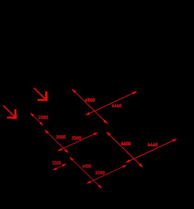
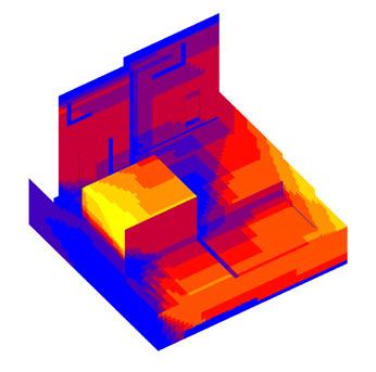
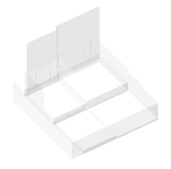
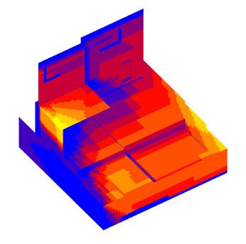
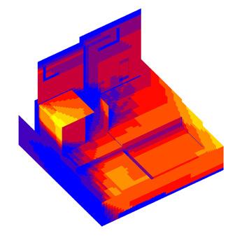
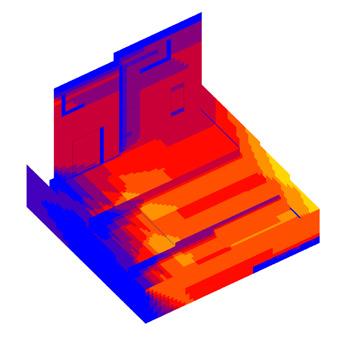
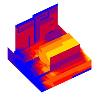
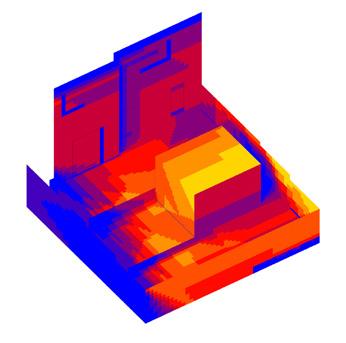
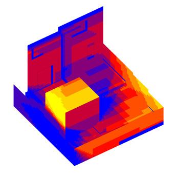
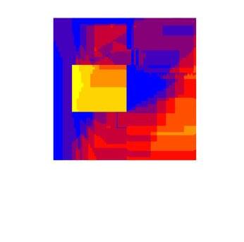
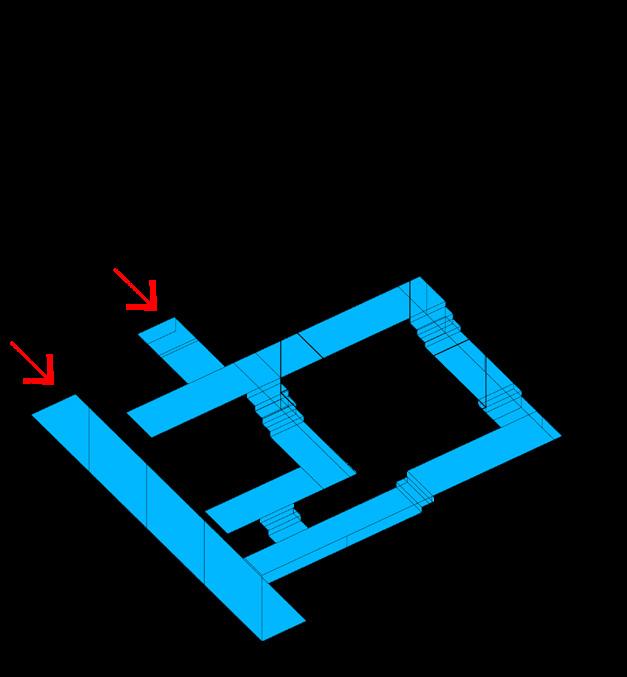
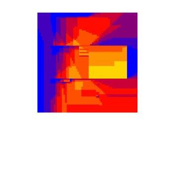
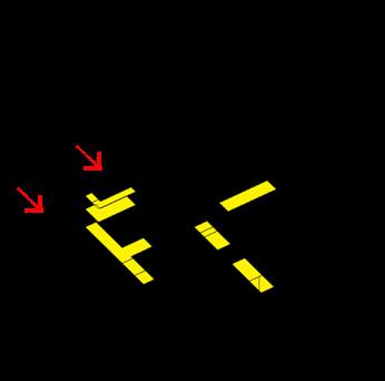
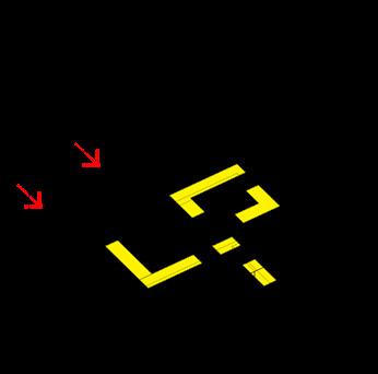
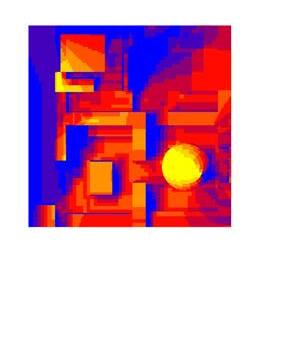
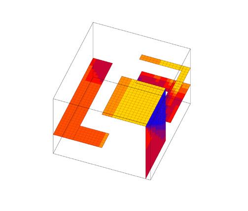
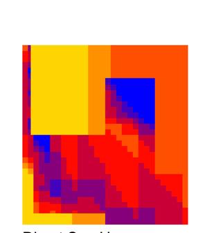
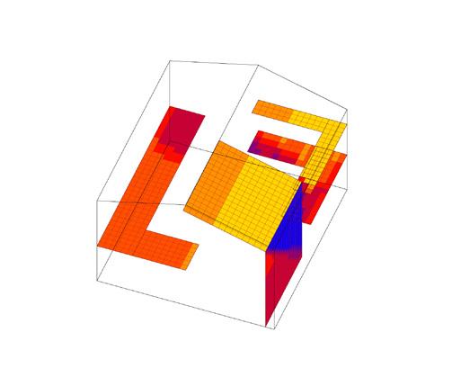
Collect environmental data at each sensor point embedded wtihin the wall at outer, mid, and inner layers
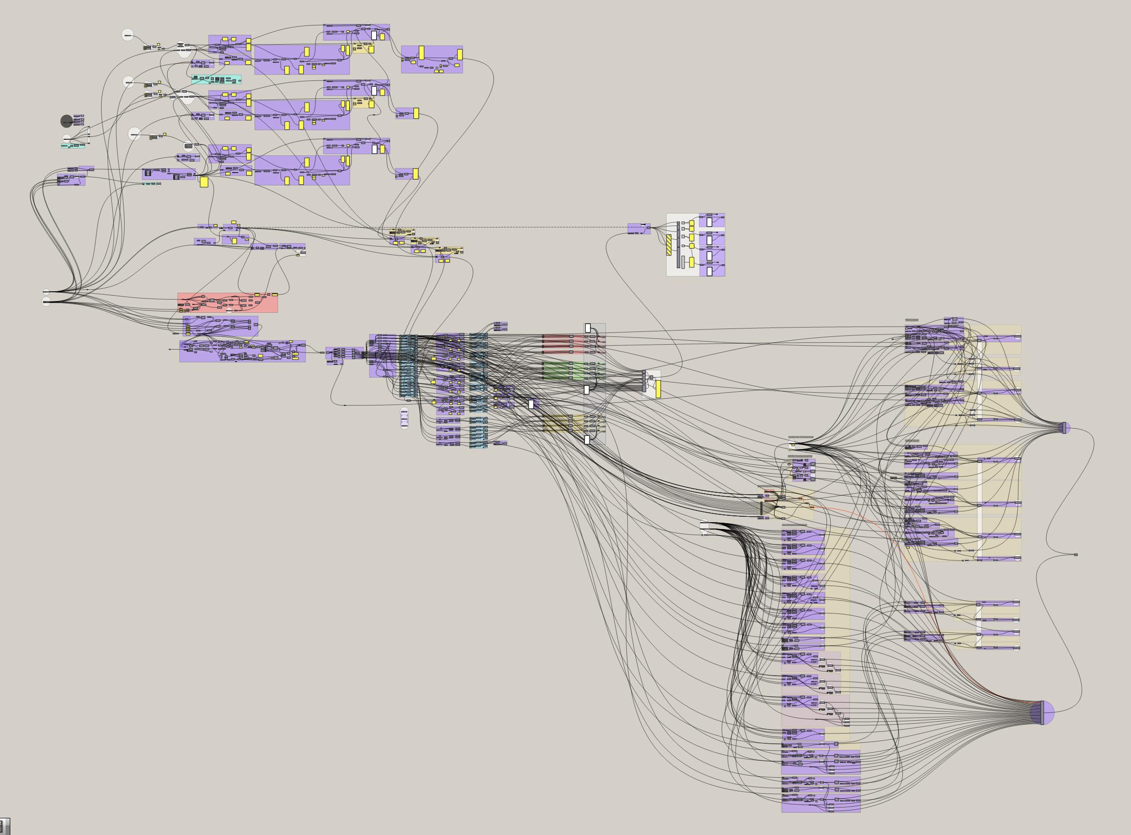
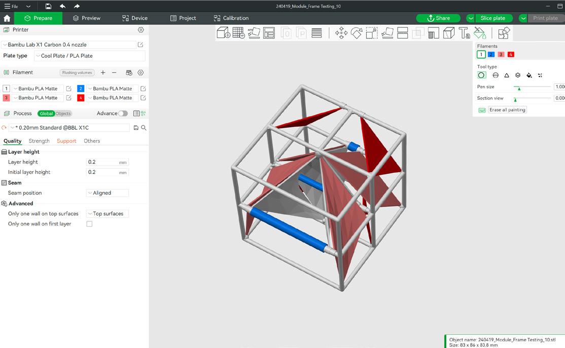
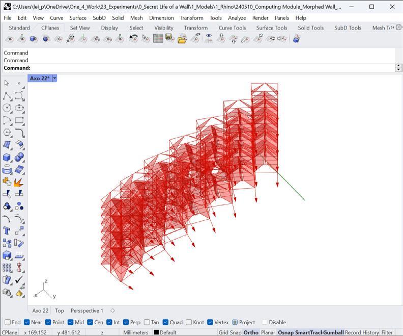
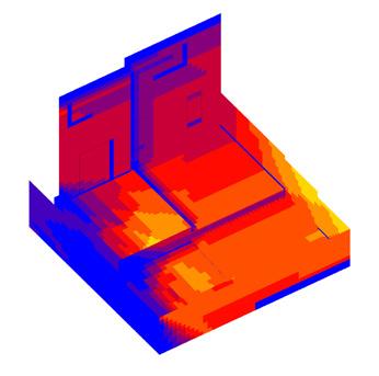
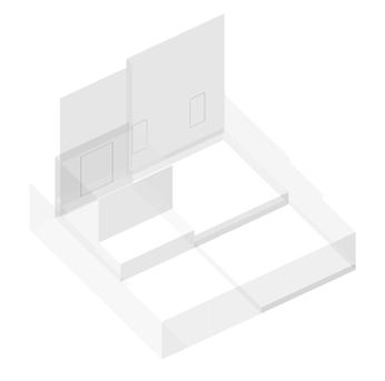
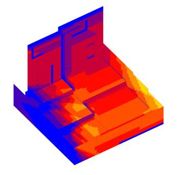
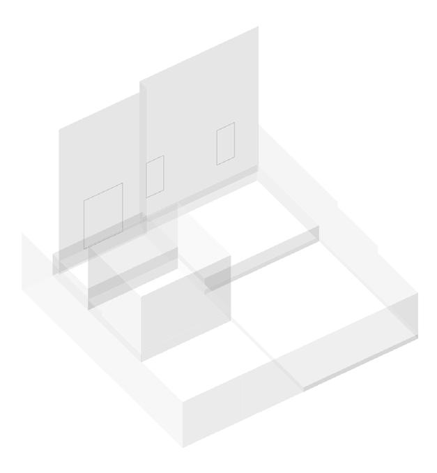
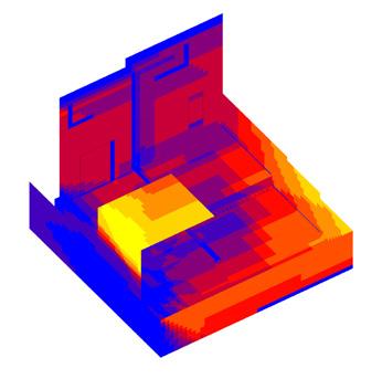
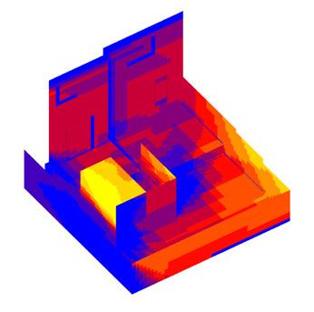
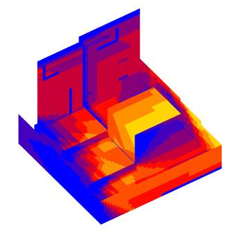
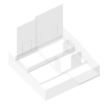
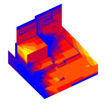
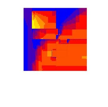
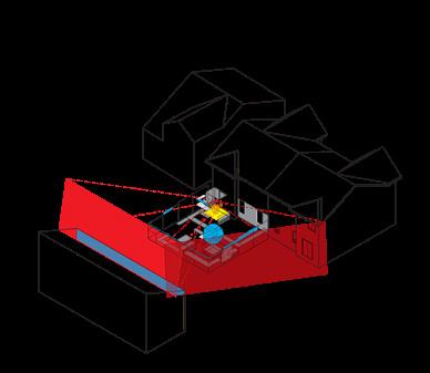
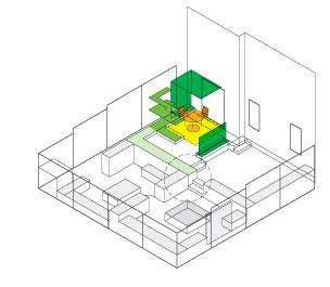
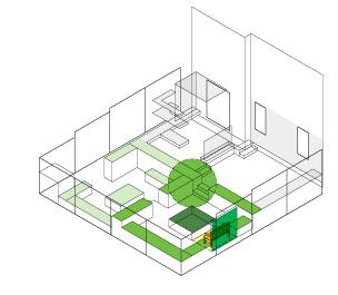
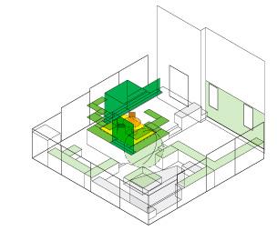
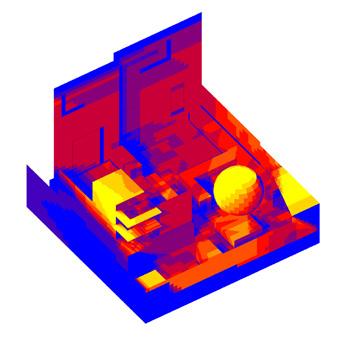
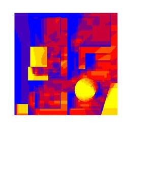
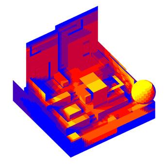
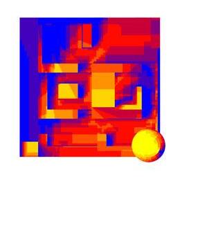
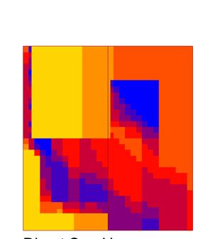
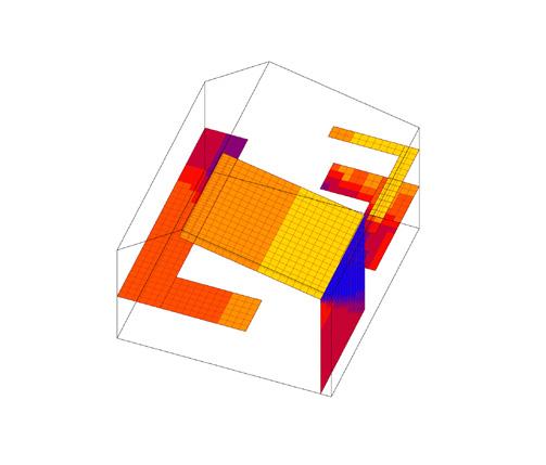
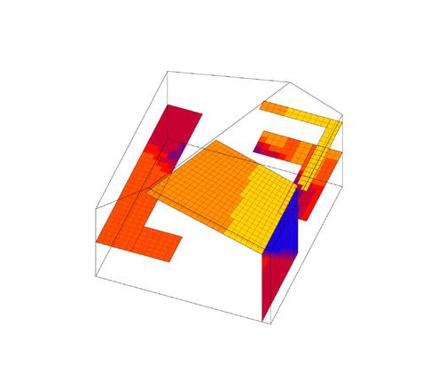
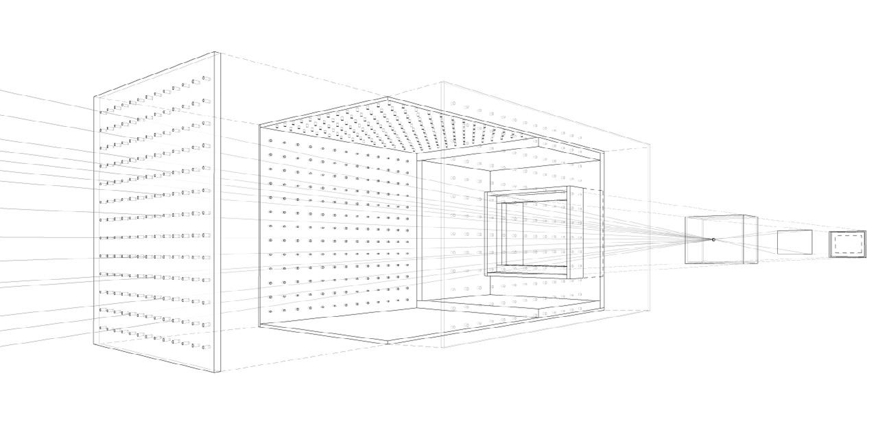
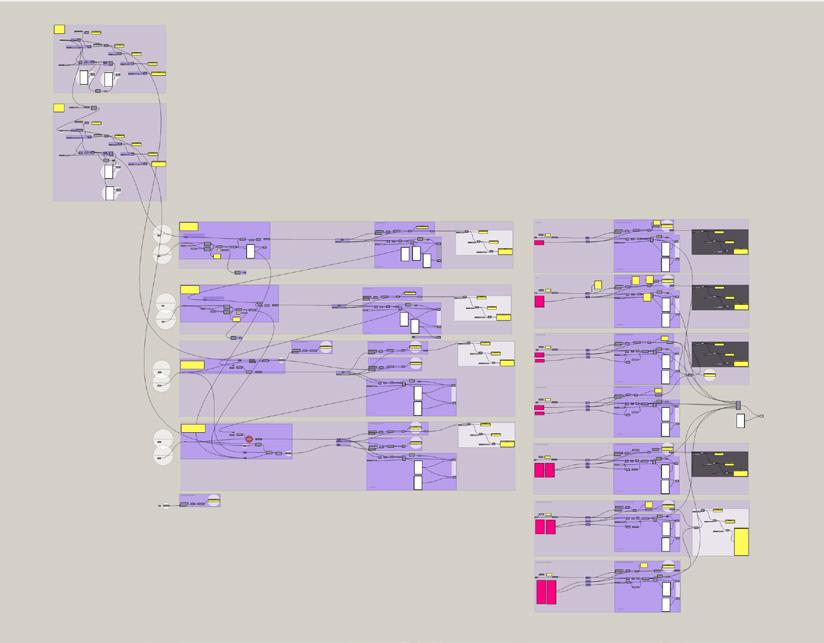
As part of the agenda of this research, the goal is to explore a circular workflow that connects sensory data collection, form generation, and 3D prototyping export through a single, live Grasshopper script. Such a workflow would allow design and prototyping to occur concurrently as the project develops. The project is modelled exclusively using Grasshopper, with Rhinoceros serving as the visualisation platform. The parametric script utilises a loop component to continuously regenerate the module output to reflect the changing sensory input. The script is set up to allow adjustments to the underlying DNA of the modules, as well as to design decisions made early on in the process, as the design develops and lessons are learnt during the prototyping and testing stage.
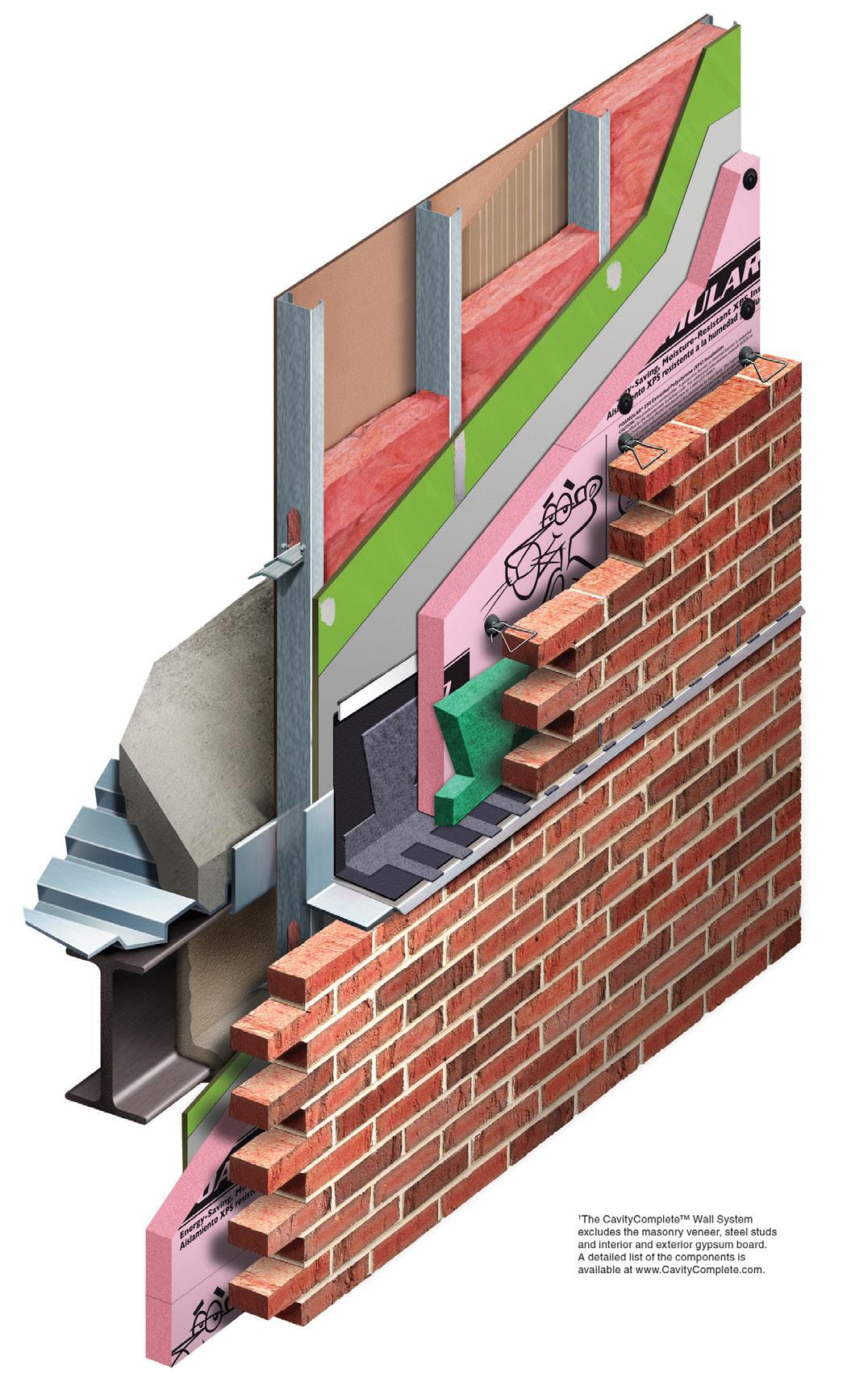
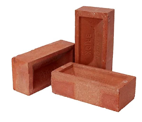
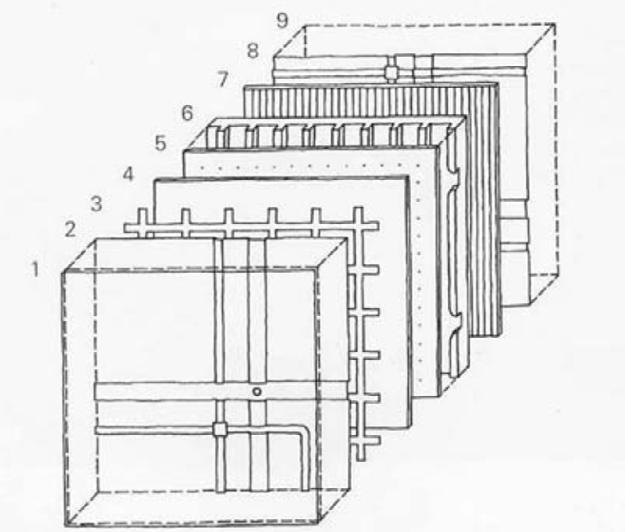
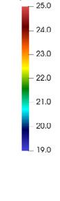
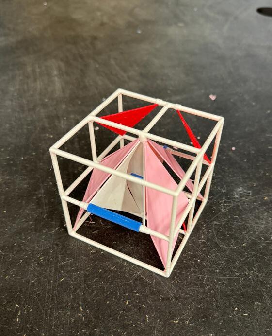
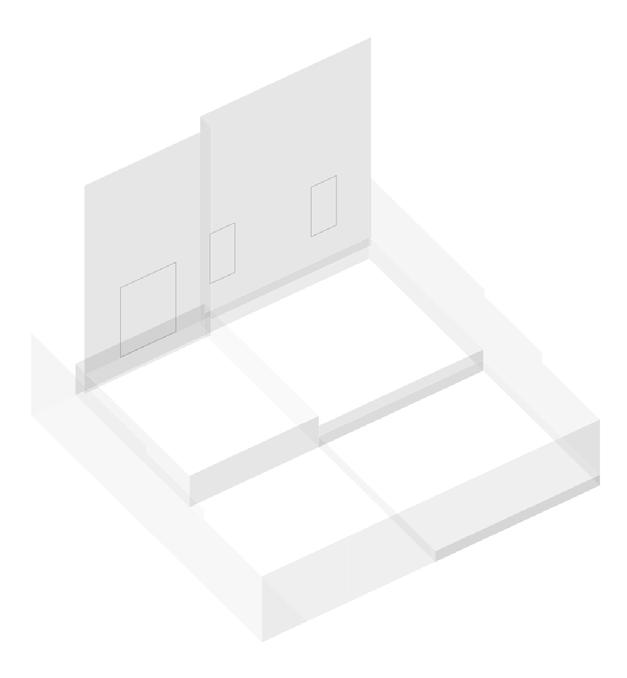
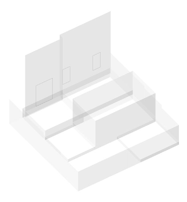
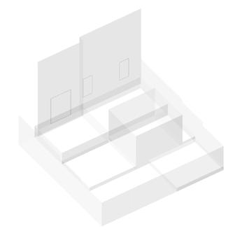
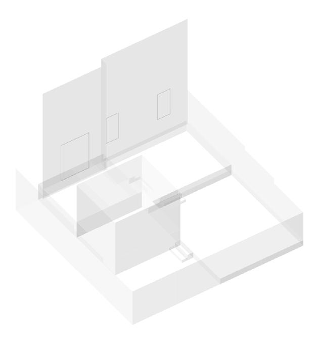
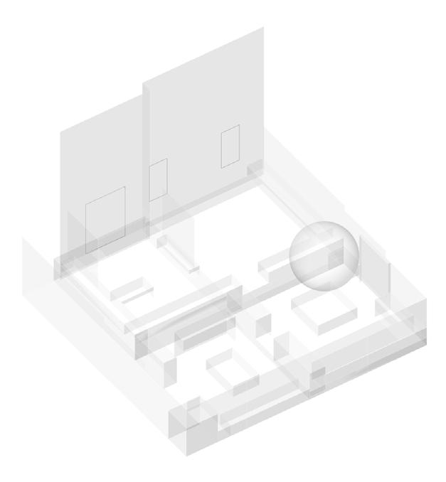
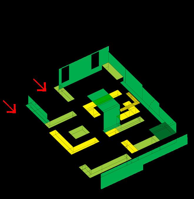
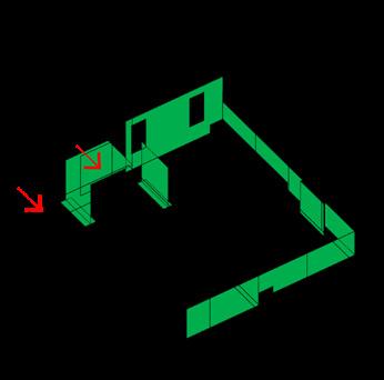
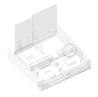
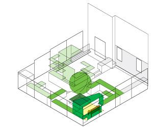
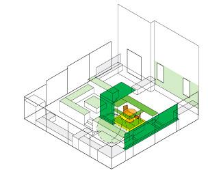
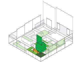
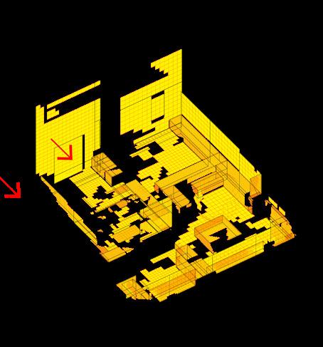
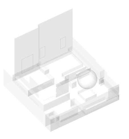
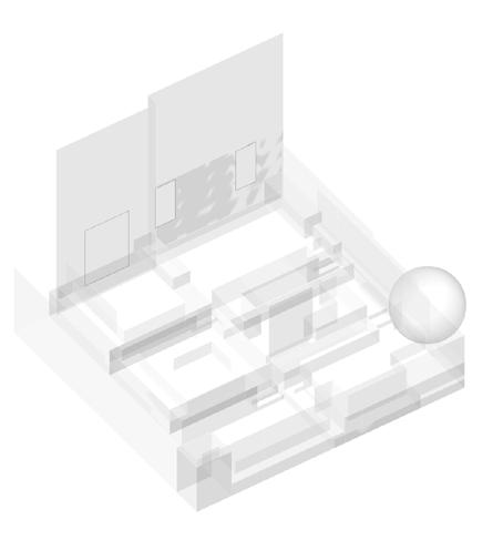
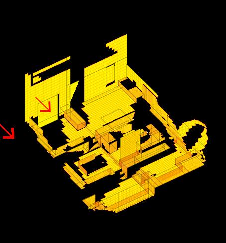
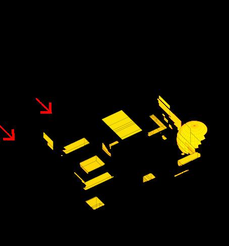
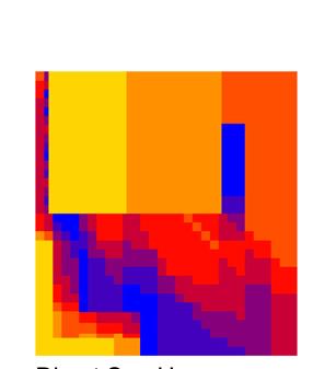
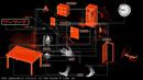
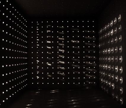
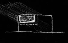
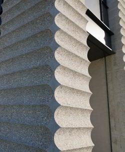
The project begins by examining the basic compositions of our typical wall systems. In specific, the functions these systems were designed to fulfil, and the basic modules created to achieve them. The next question is: what if a wall were to fulfil a different set of functions? What form would the basic modules of this system take, and how might this alternative wall behave? On one hand, this research focuses on the interpretation of our walls as the site where multiple environmental and psychological events converge. On the other hand, it explores a set of new functionalities which were made possible by the latest material technologies, such as meta and composite 4D materials. For the experiment on an alternative wall system, the functions of data collection and integration are selected, to be achieved through the use of stimuli-responsive material components.
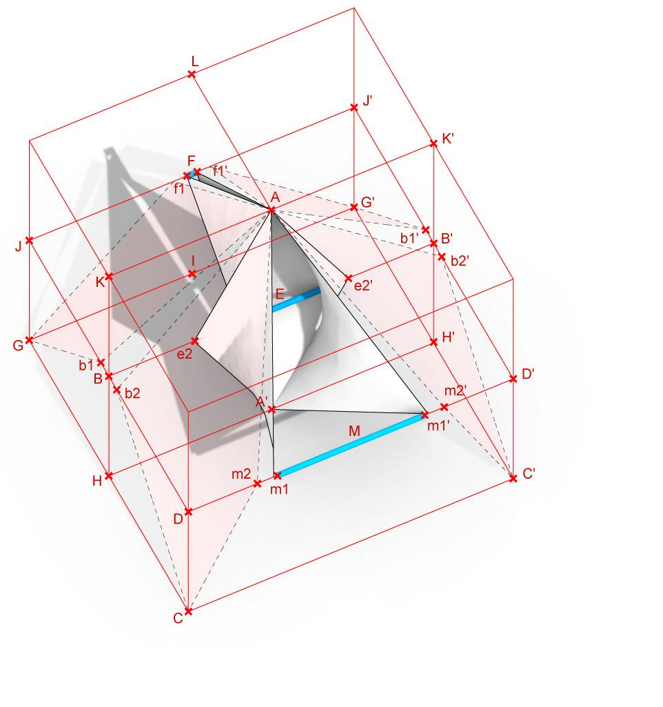
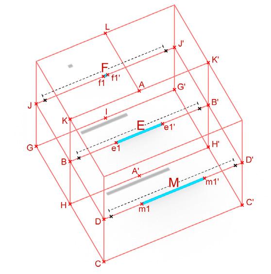
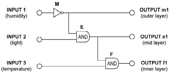
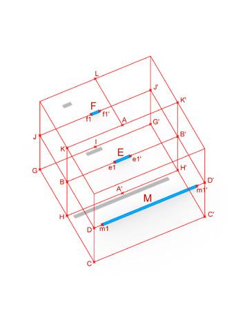
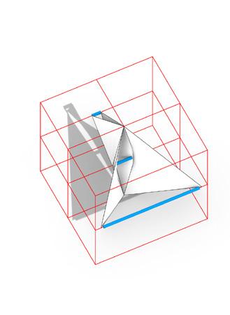
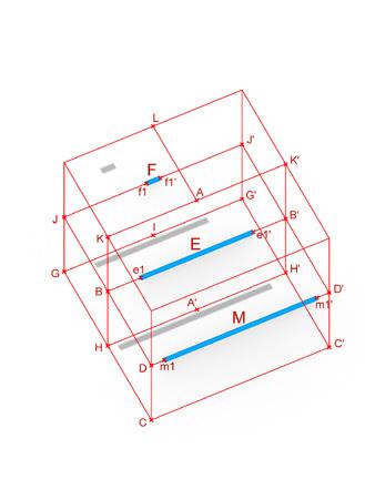
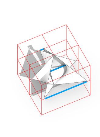
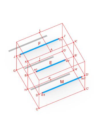
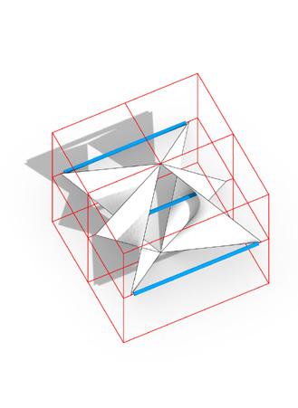
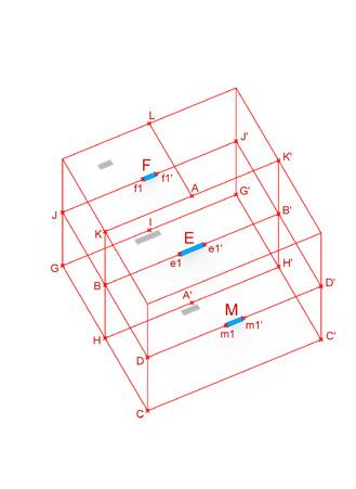
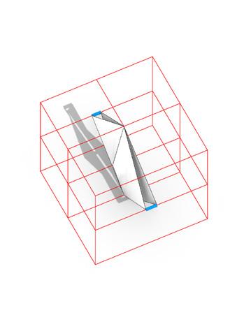
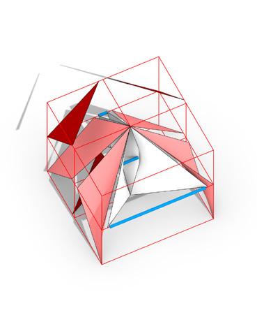
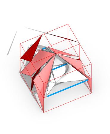
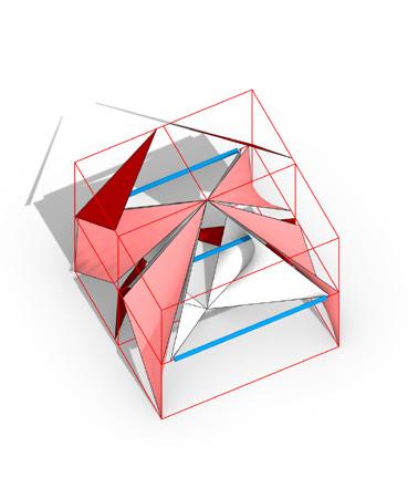
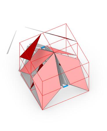

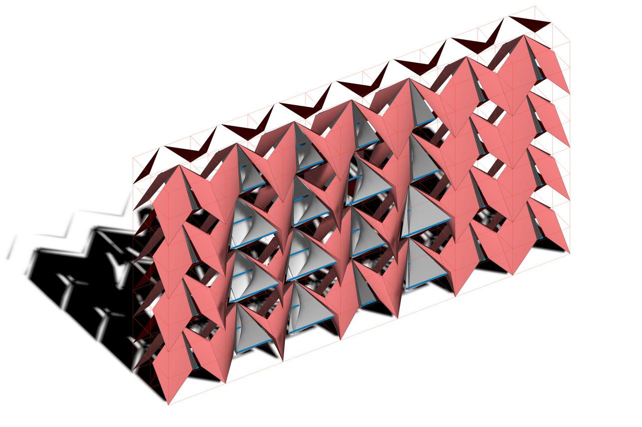
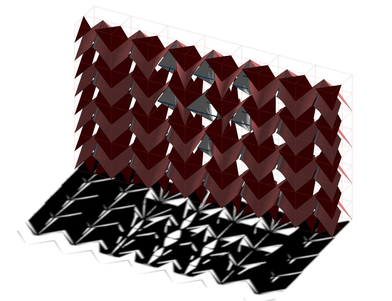
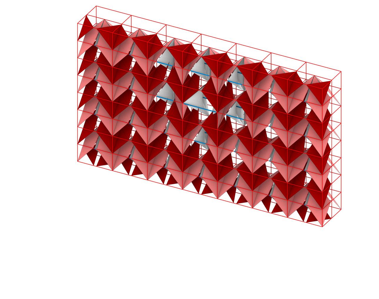
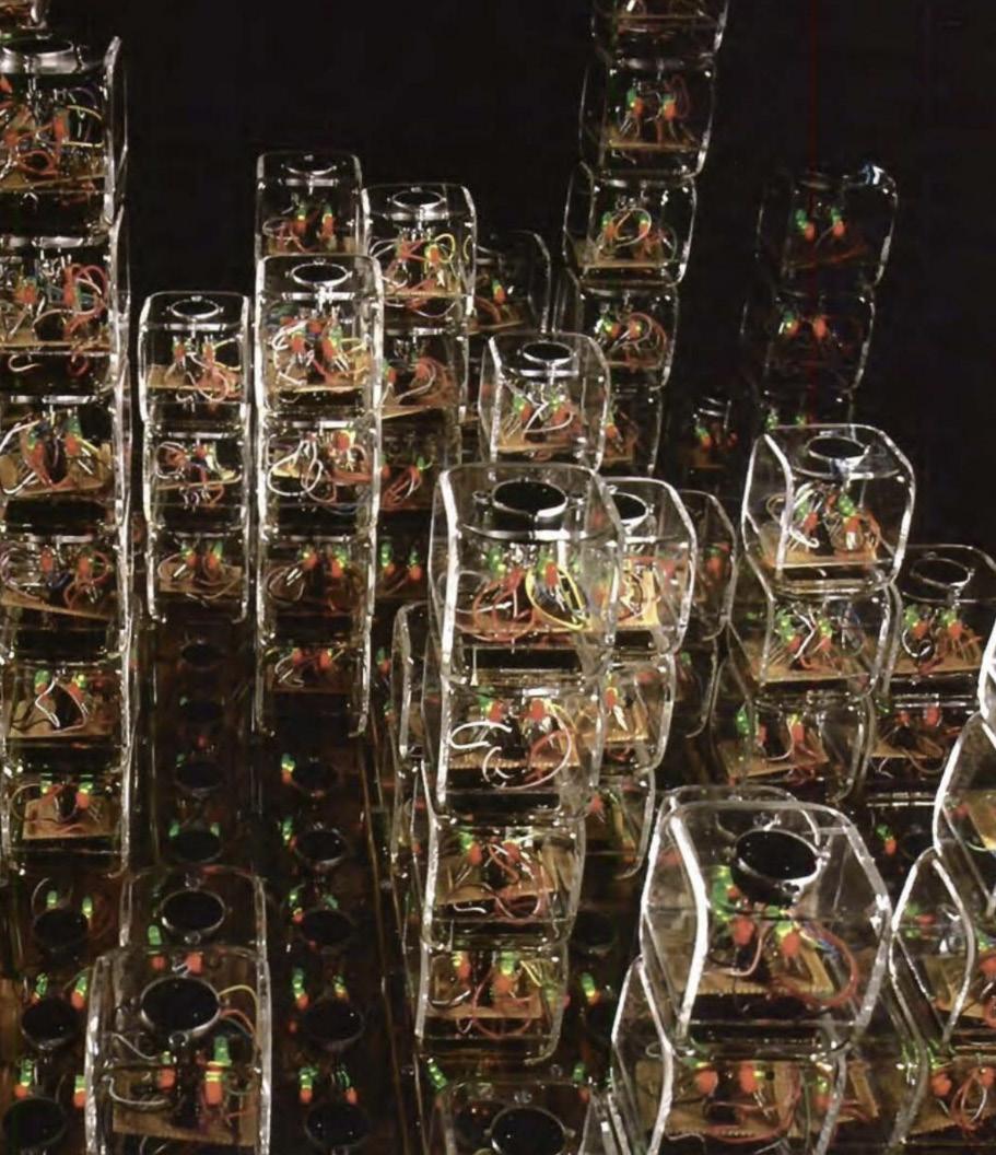
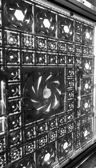
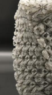
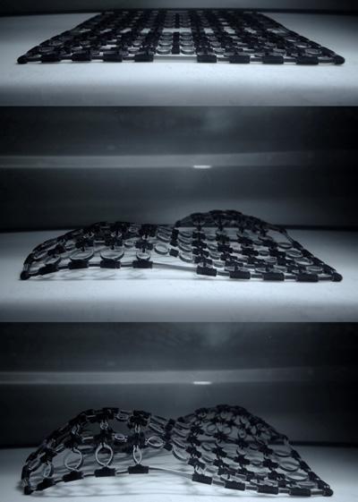
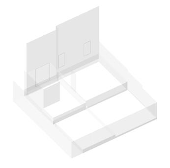
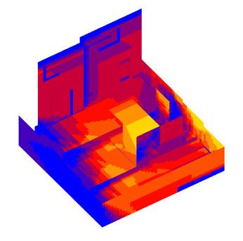
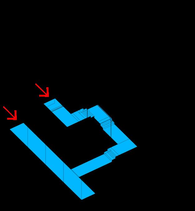
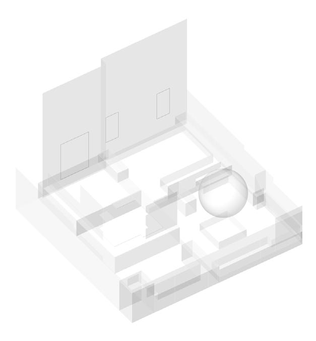
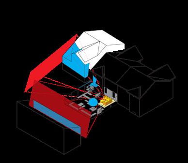
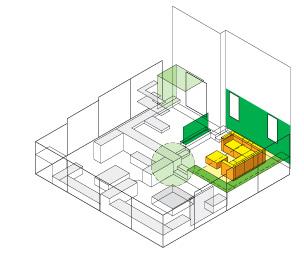
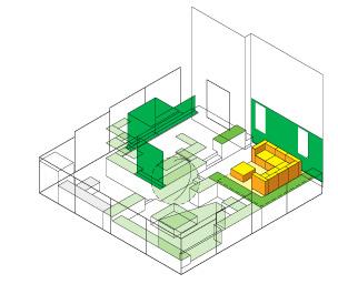
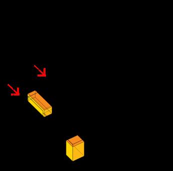
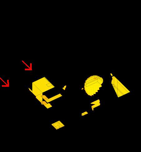
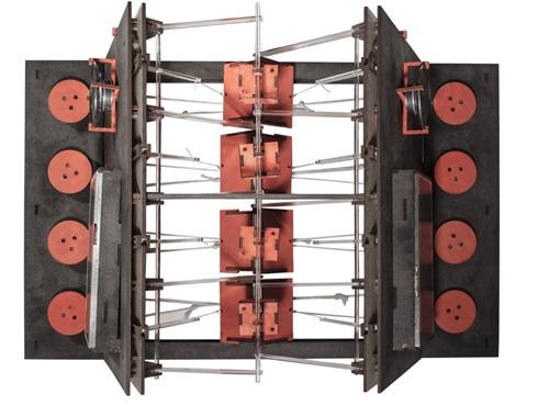
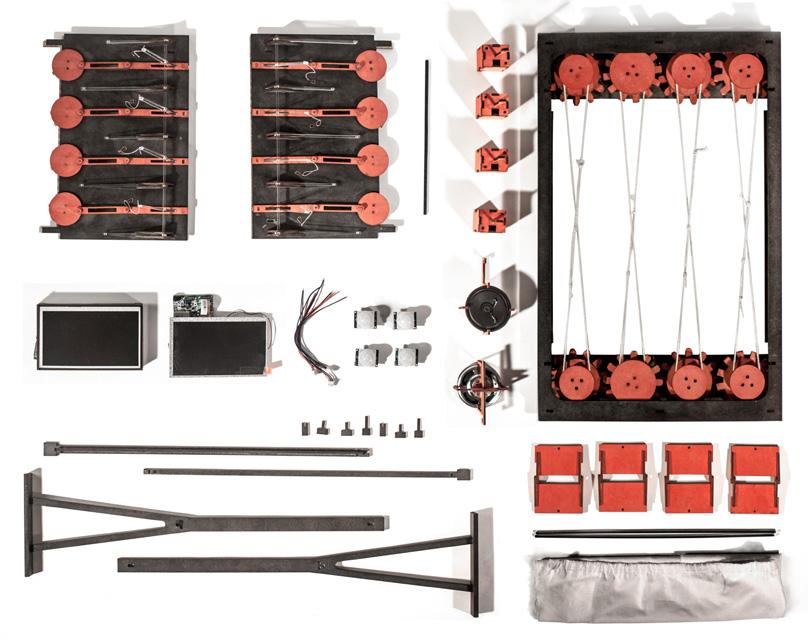
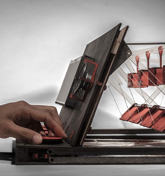
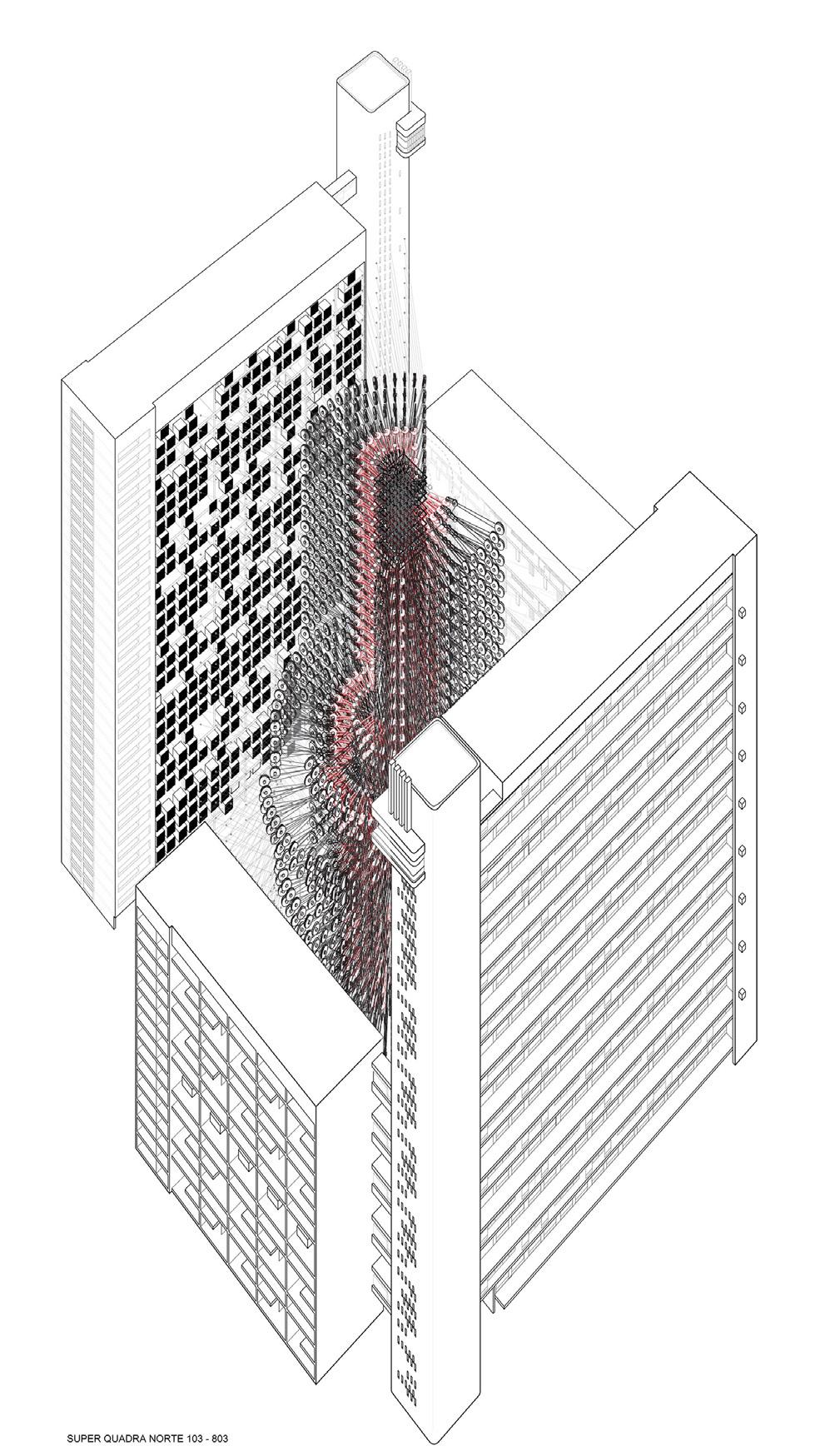
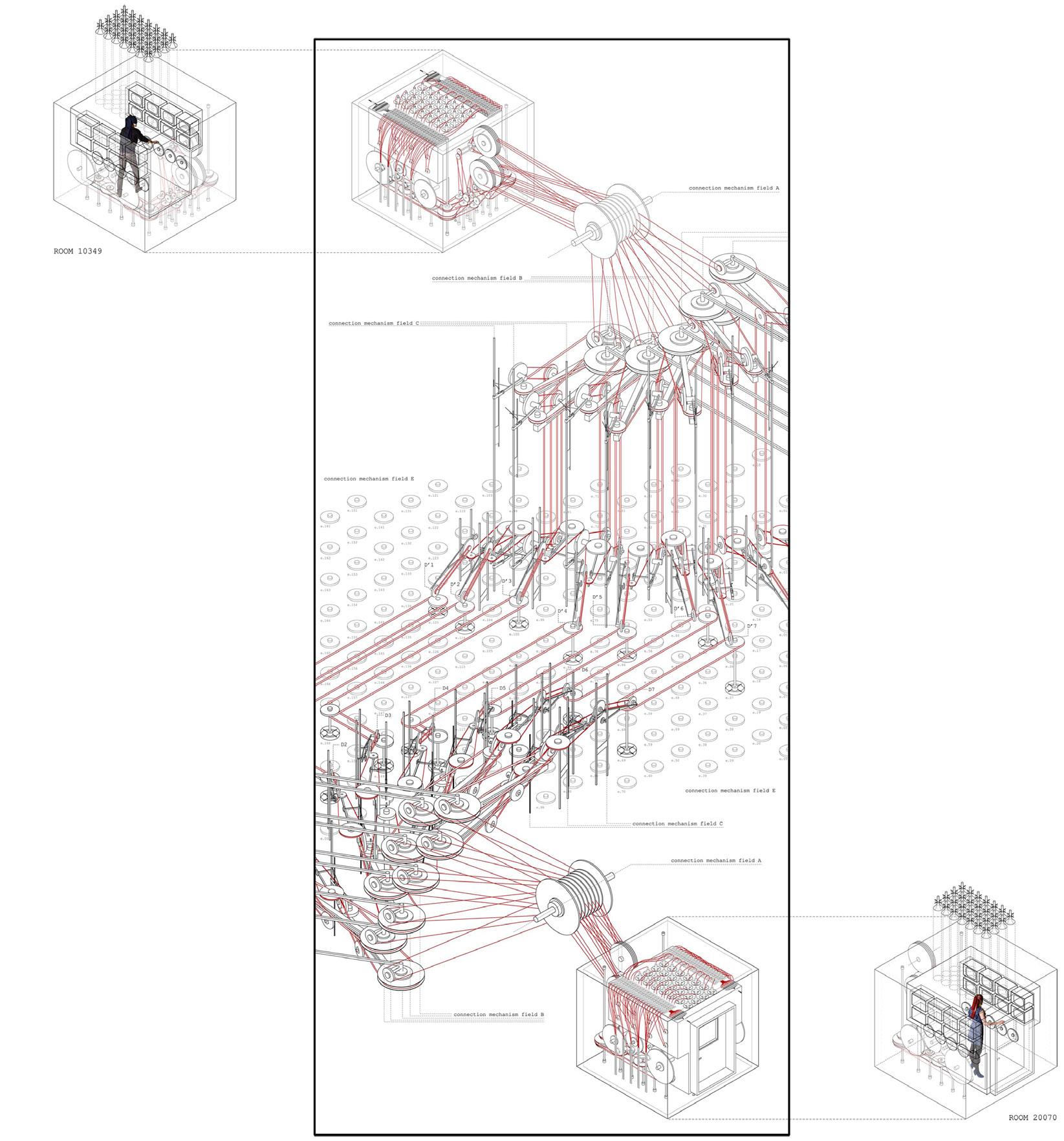
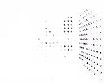
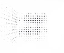
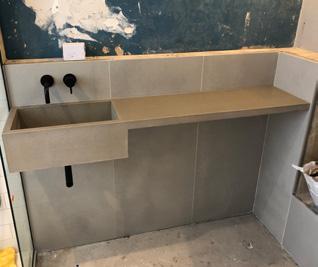
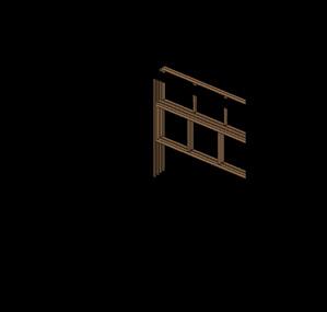
The basic unit of this alternative wall is the computing module. Data collection is achieved at three designated sensory points within each module, each composed of stimuli-responsive materials (SRMs) reacting to A selected environmental signal, such as daylight, humidity, temperature, or user-induced electric current. The transforming SRM components would then trigger subsequent changes in the shape and position of the tensile components, creating different configurations within the module, communicating the state of the surrounding environment to the observing users. Data integration is achieved when multiple modules are placed together to form a system. The transforming pattern in the wall, created by the changing positions of the tensile structure operated by the SRM components, reveals the invisible interactions between the fields of the three environmental forces.
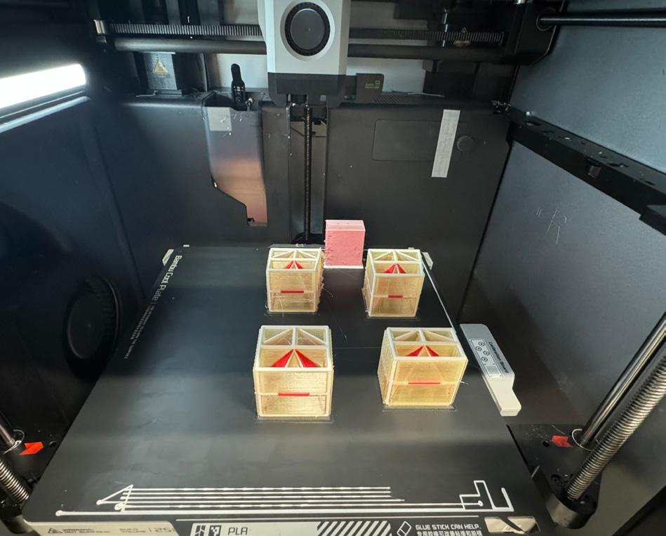
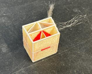
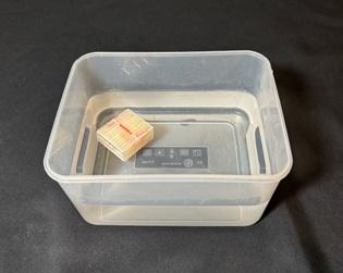
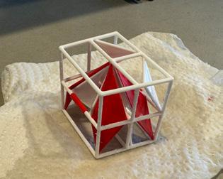
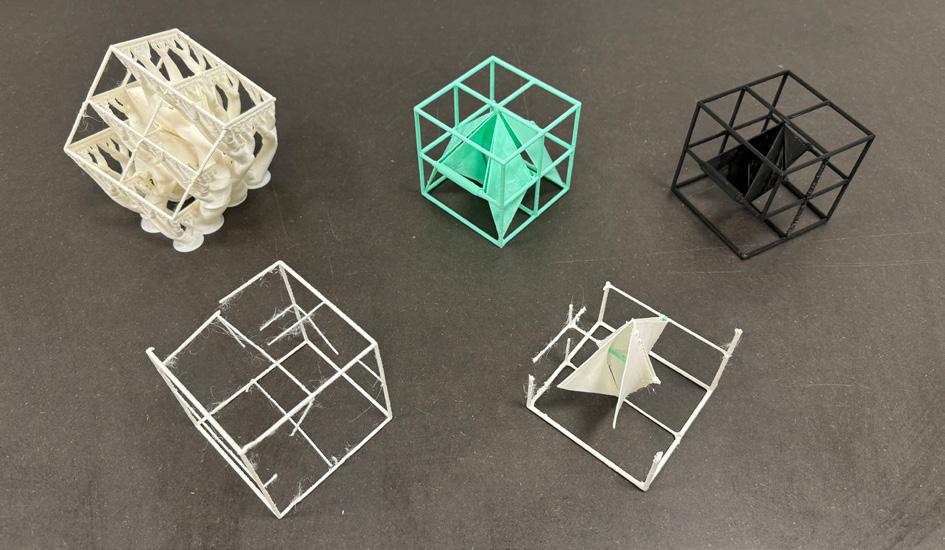
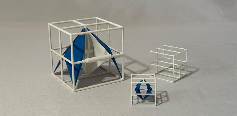
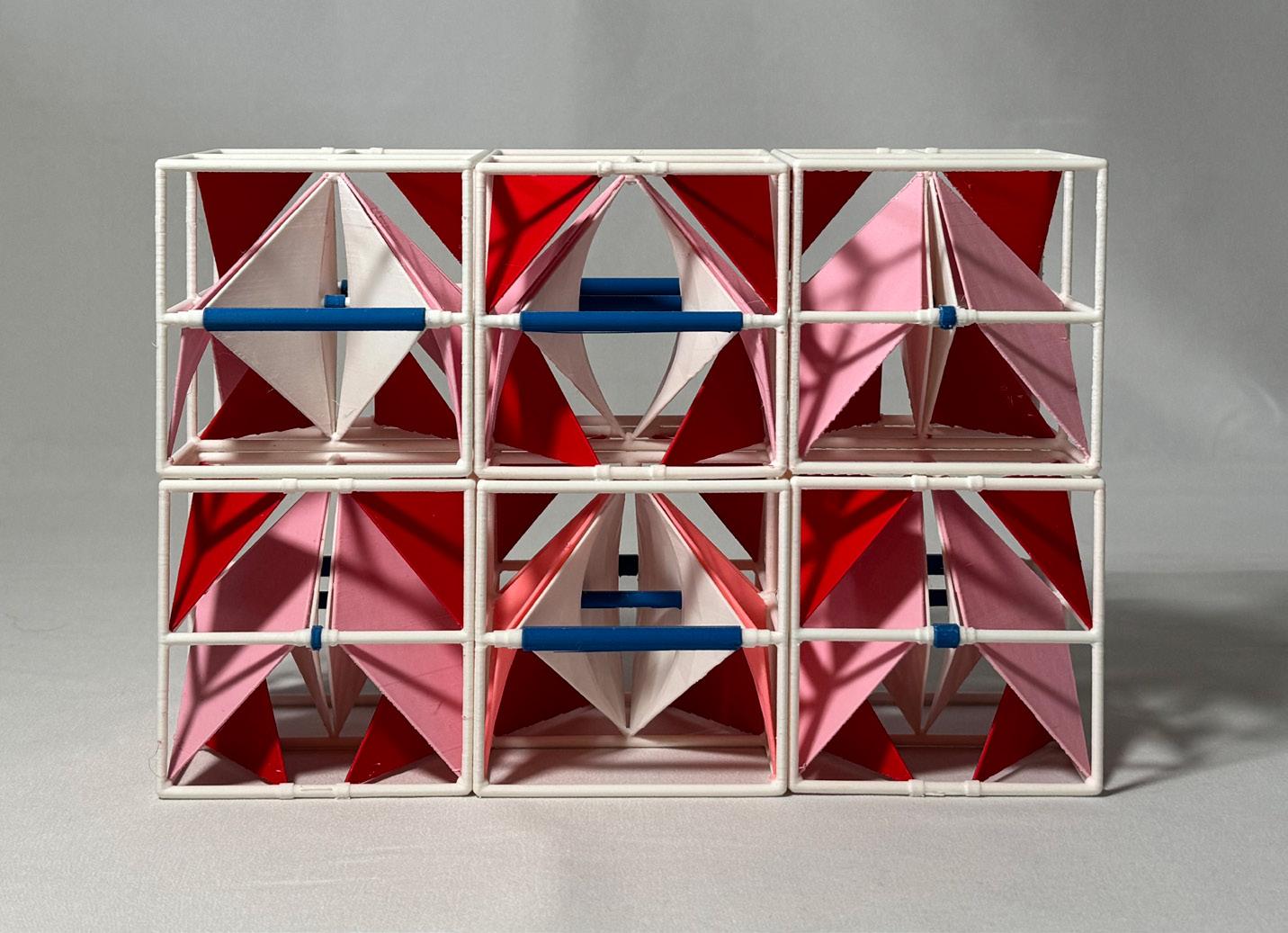
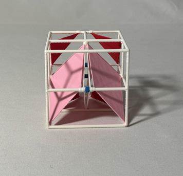
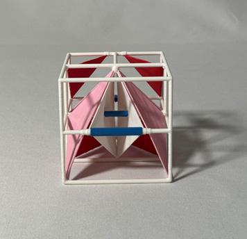
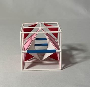
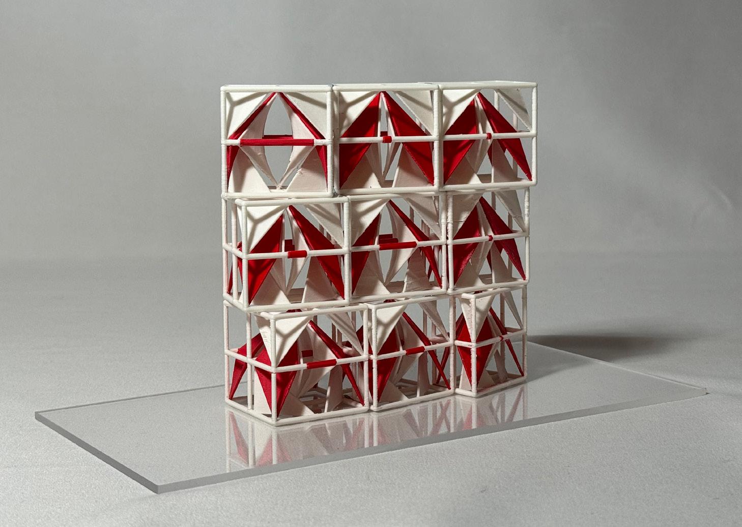
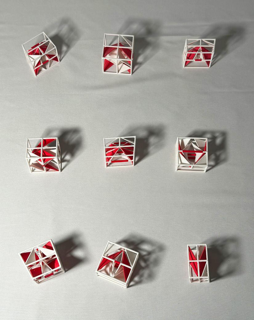
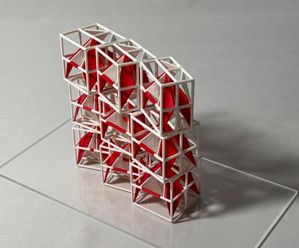
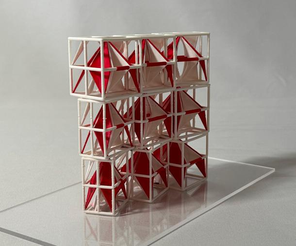
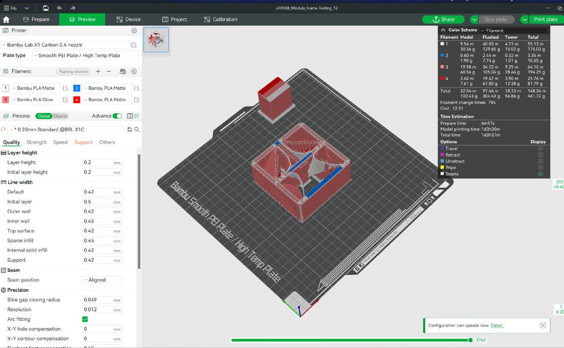
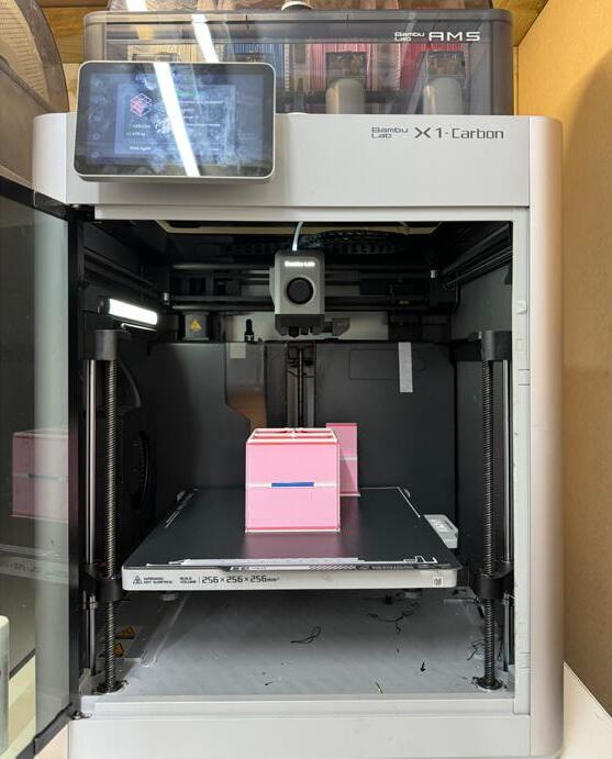
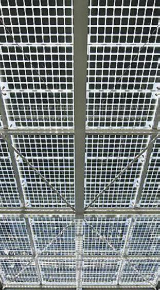
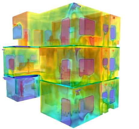
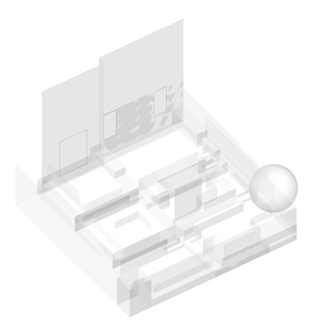
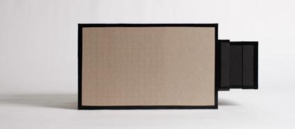
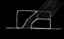
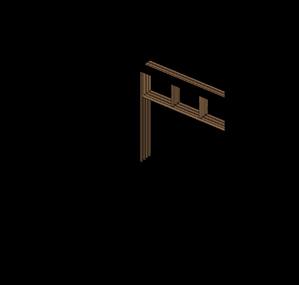
In the age of digital design, which allows us to explore complex geometric forms rapidly in a virtual environment, it is easy to neglect how these abstract planes and lines may take on thicknesses and substances. Therefore, one of the focuses of this project is the incorporation of materialisation design as part of the digital design development process. Prototypes of the modules were produced in parallel with the design of the module itself, allowing lessons learned from fabrication considerations and constraints to influence the development of the underlying parameters and algorithms early on. Early-stage prototype testing includes exploring different fabrication support methods, materials, dimensions, and internal configurations of the components themselves.
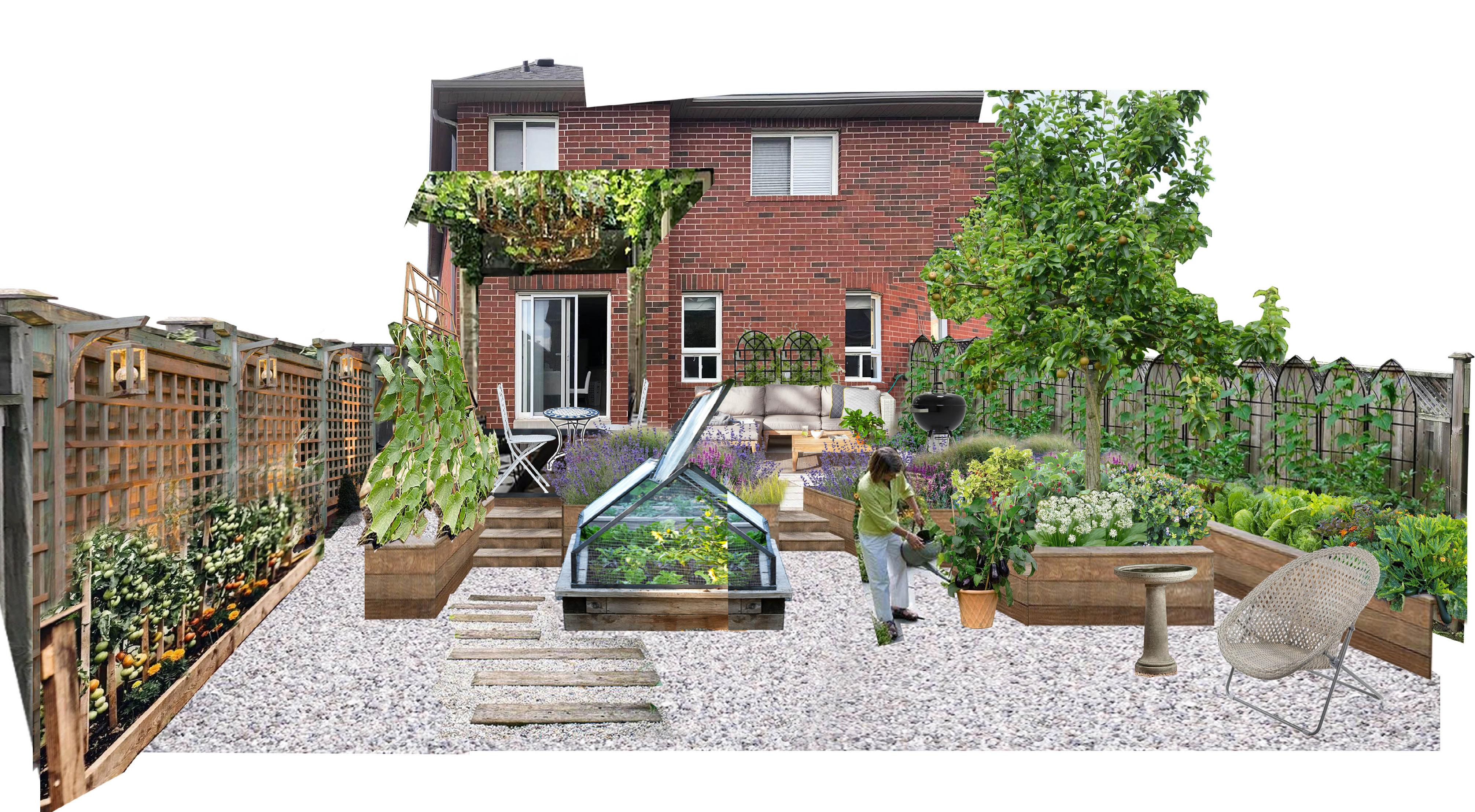
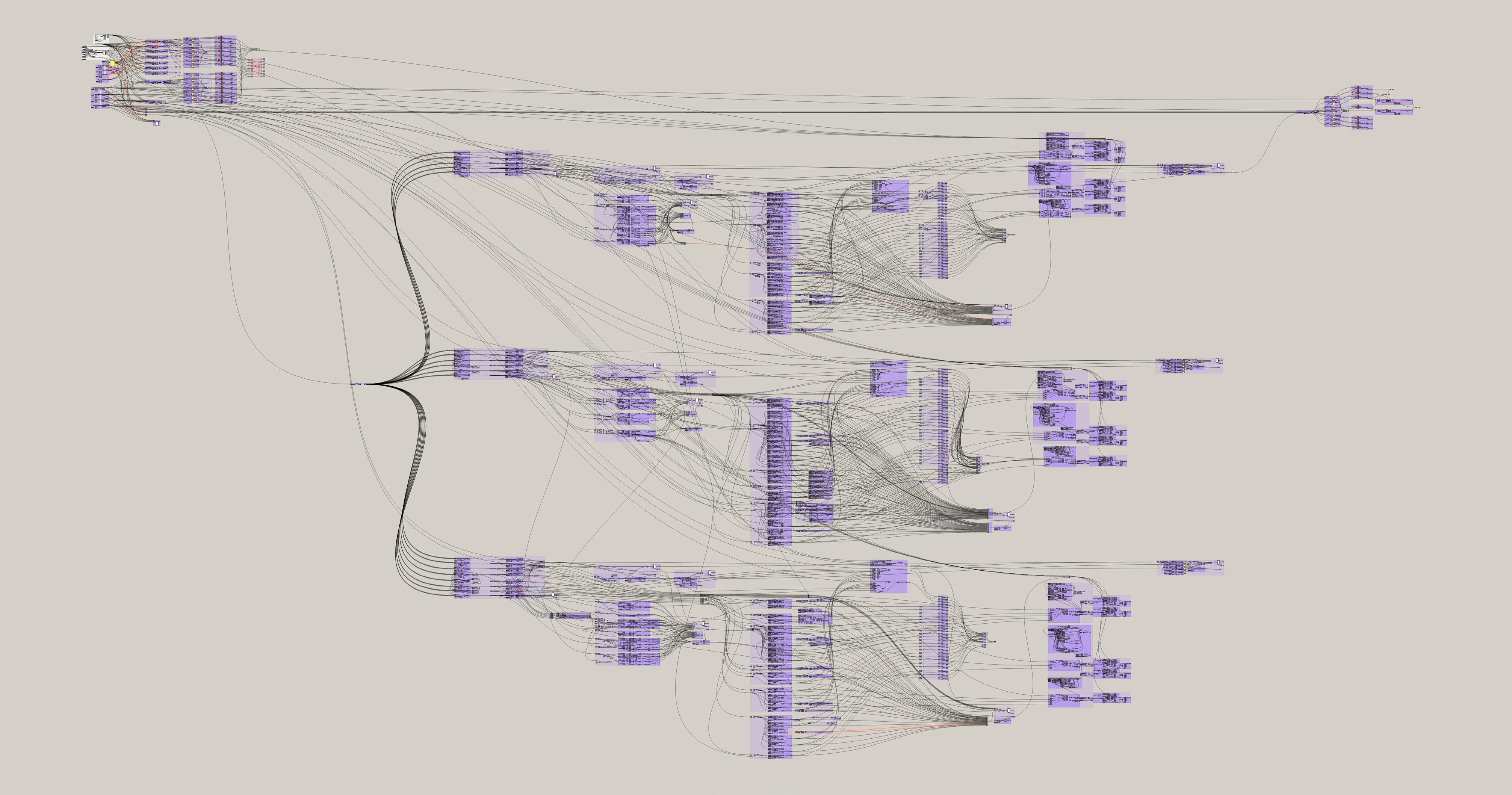
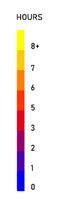
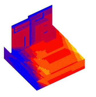
Provision of design options is a common practice in the industry. However, it is often carried out as an afterthought and executed haphazardly. This project partly serves as an opportunity to explore the incorporation of optioneering into a normal Grasshopper workflow. The project is executed in Grasshopper using the Ladybug plugin for microclimate assessment and Rhinoceros as the visualisation platform. Three potential design directions were identified at the beginning of the project. The script is set up to allow exploration of the three options in parallel using the same set of underlying project and design parameters. Performance data were collected on each key evaluation criterion for comparison at decision points. Access to sunlight, being the key criterion for a productive garden, was used as the guide for the design throughout the development process.
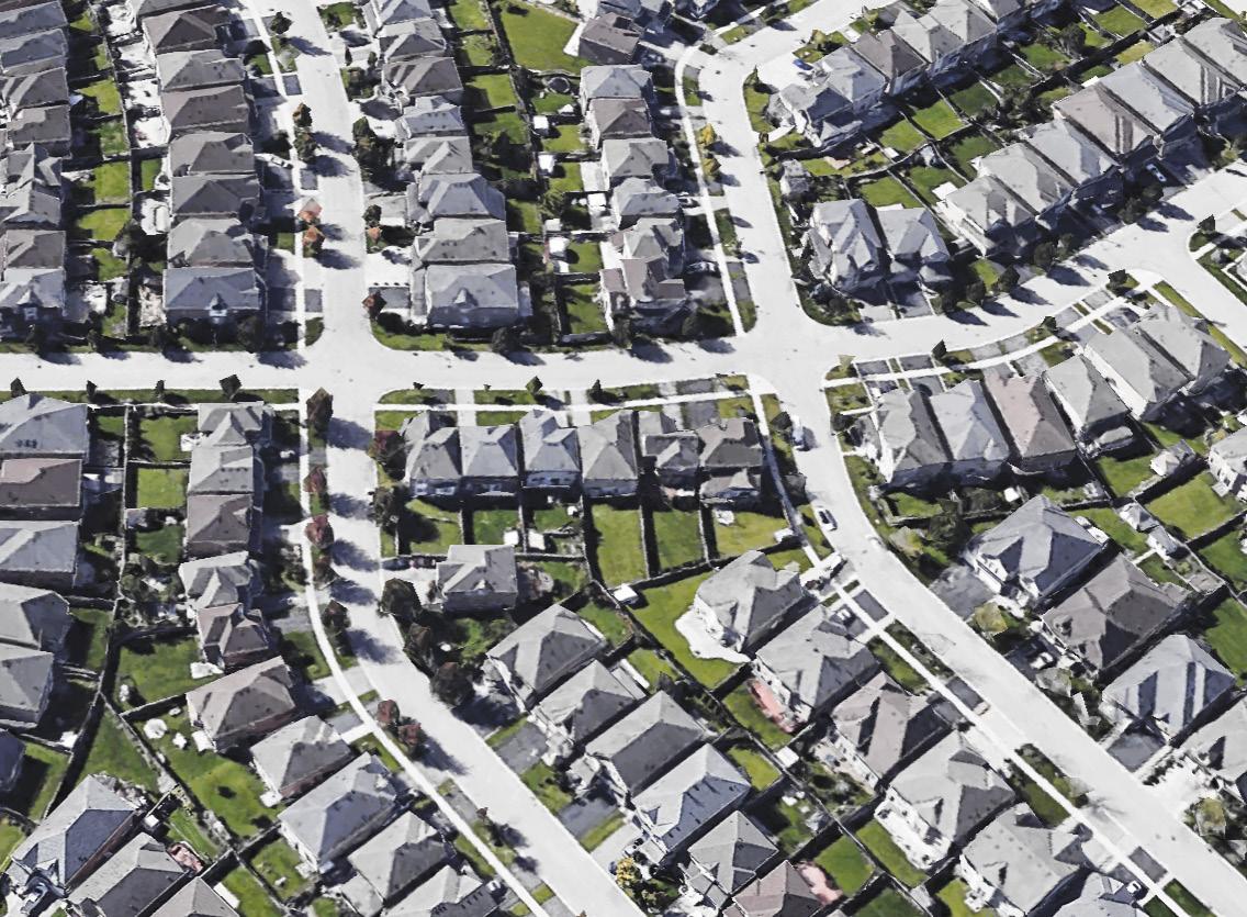

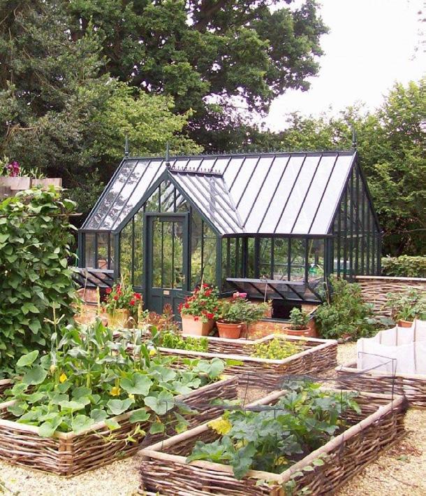
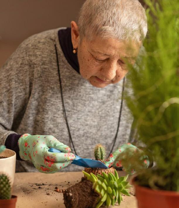
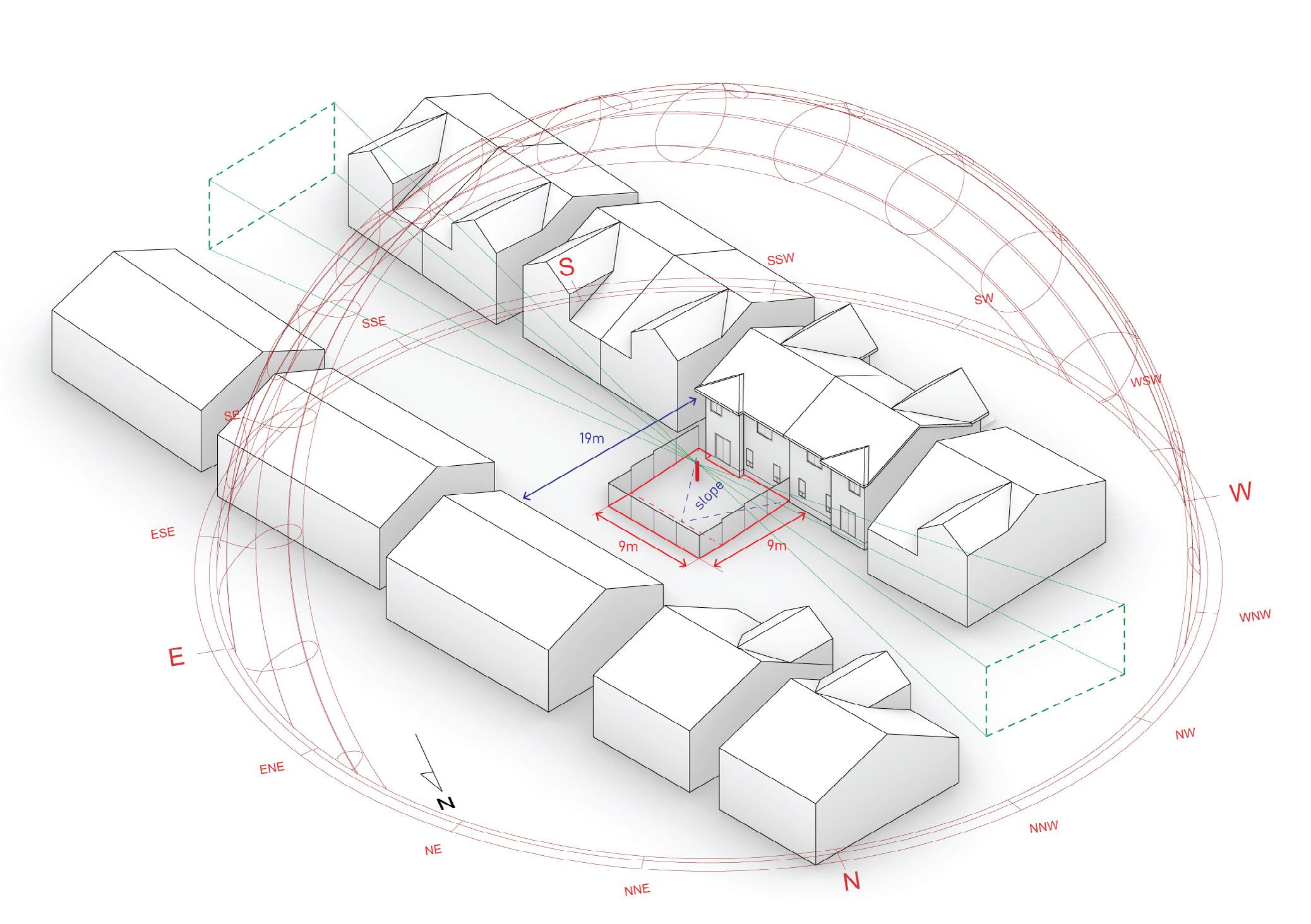

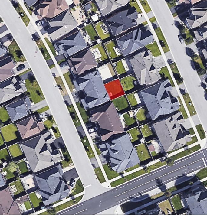
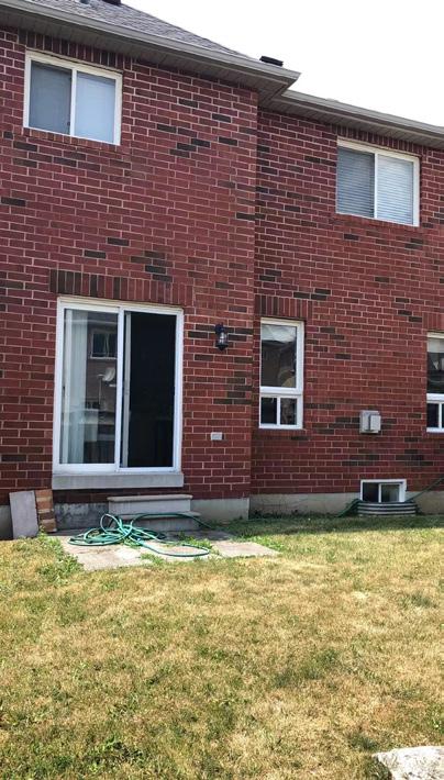
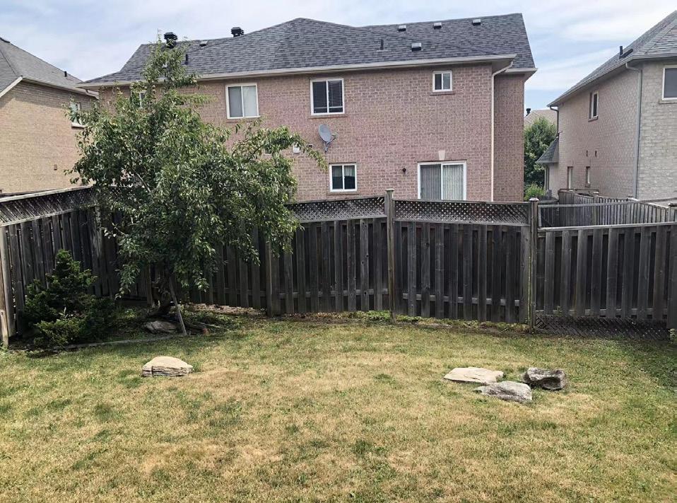
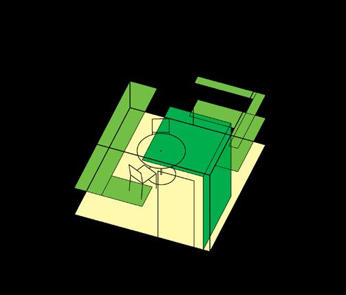
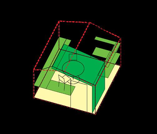
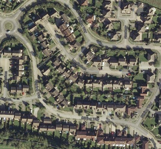
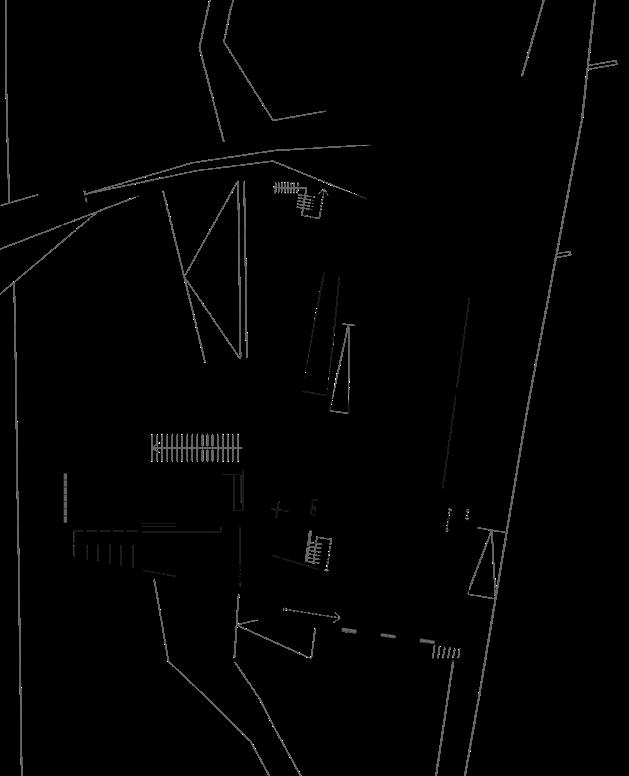
Backyards are a common feature of North American suburban living, yet they are often underutilised and non-productive. The site for this project represents a typical example of this landscape of idle greenery. This project looks at transforming the existing site into a productive garden, with emphasis on elderly-friendly garden design and use of garden features to create focal points and frame views away from overlooking neighbouring buildings. The design is largely inspired by traditional English cottage gardens. Elderly friendly garden features adopted include standing and seating height planters, covered outdoor seated gardening space, and a pebbled instead of lawned garden.


Six key design criteria or challenges were identified for the project. The design development process focuses on exploring interventions to address them. They include: 1) the existing slope in the garden, which makes it difficult to use, 2) a lack of covered outdoor seating area, 3) incorporation of a path for wandering, 4) optimization of the amount of productive planter area, 5) creation of focal interest for the activity zones and minimization of overlooking issues with neighbouring properties, and 6) maximisation of sun hours at the planting area.


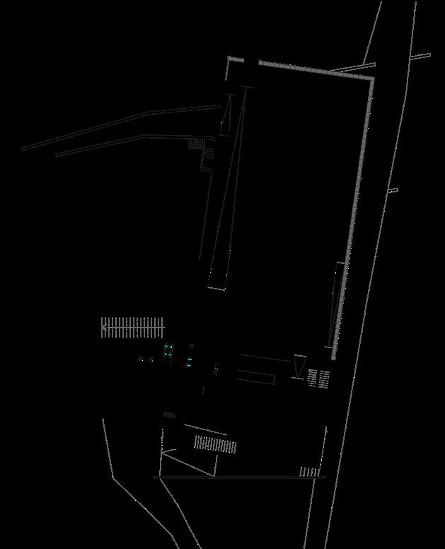
The three options selected for design development feature: 1) a three-terrace division with the pavilion attached to the main building, 2) a four-terrace division with the pavilion away from the main building, acting as a screen between the internal dining area and the neighbouring building, and 3) a five-terrace division with the pavilion located furthest away from the main building, acting as a screen between the group seating area and the neighbouring building. The design criteria were reviewed and developed for all three options in sequential steps. The Grasshopper script was composed to allow decisions made at earlier steps to be adjusted or revisited as the design develops.
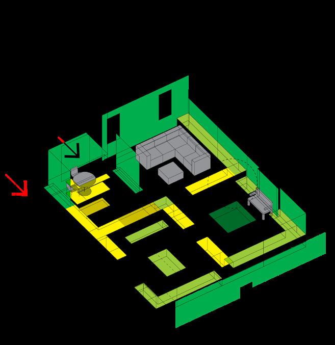

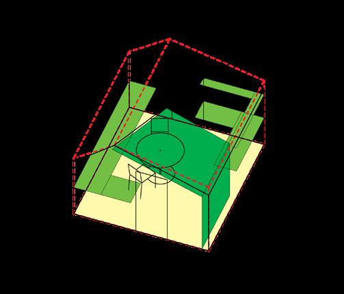
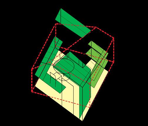
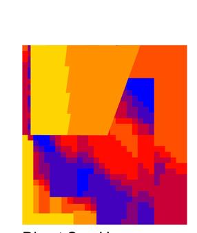
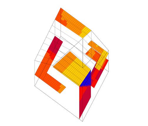
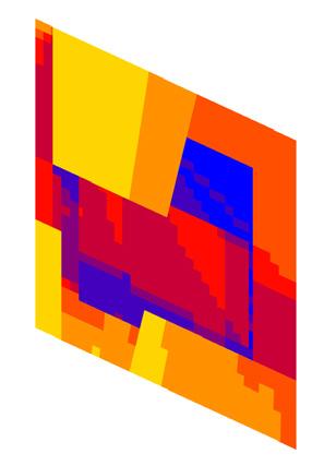
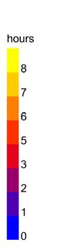
At the decision point of this design stage, the outcome and performance of each option on the six design criteria were reviewed both qualitatively and quantitatively. Option selection could be based on personal preference or project priorities. In this instance, Option C was selected due to its optimal sunlight performance in the planting areas and the client’s decision to prioritise privacy in the group seating area over the outlook. A new round of the optioneering process would then begin with Option C as the starting point for the next design stage. This project is currently at Stage 3, progressing through the design development for the feature pavilion.
<< Click to view video via browser
2014 - CURRENT FIVE YEAR PROJECT (AA SCHOOL OF ARCHITECTURE)
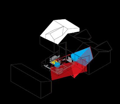
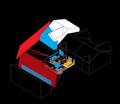
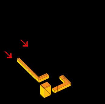
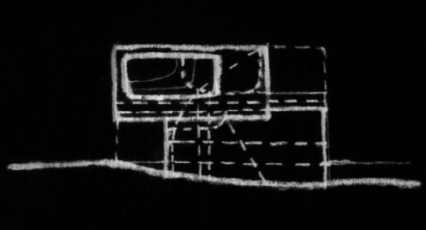
The site of this project is the standard houses in which the majority of the population lives. By understanding what actually happens inside these homes, this project attempts to rethink how a flexible and adaptable standard house should be defined and how it might look.
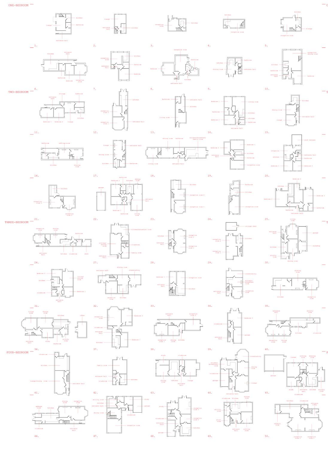

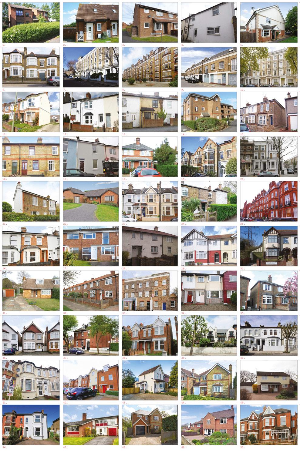


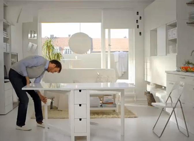

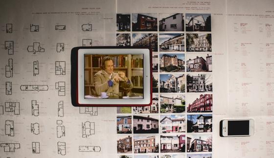
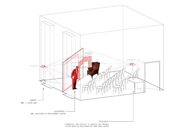
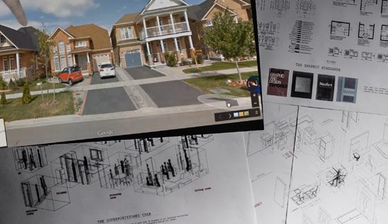
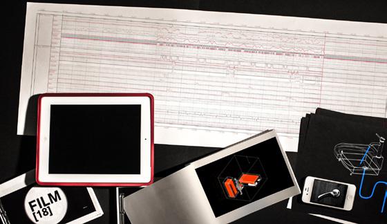
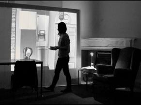
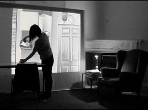
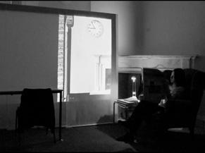
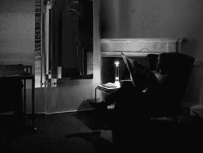
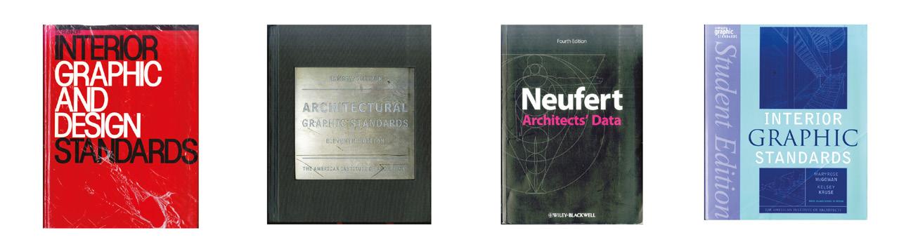
This project begins by asking, ‘What kind of houses do we live in nowadays? What do they contain? And how are they arranged?’ An examination of 50 houses on the market reveals a landscape of standard houses generated from the rules of our housing design guides and graphic standards. To adapt these inflexible standard houses into personalised living environments, smart technologies and makeshift furniture are used to adjust the built environment to the occupants’ bespoke situations and fluctuating needs. The question is, ‘is it not possible to have a ‘flexible standard house’? To explore the time- and userdependent behaviours of our physical environment, film sets and projection installations were utilised to discuss, challenge, and reimagine the idea of a standard house.
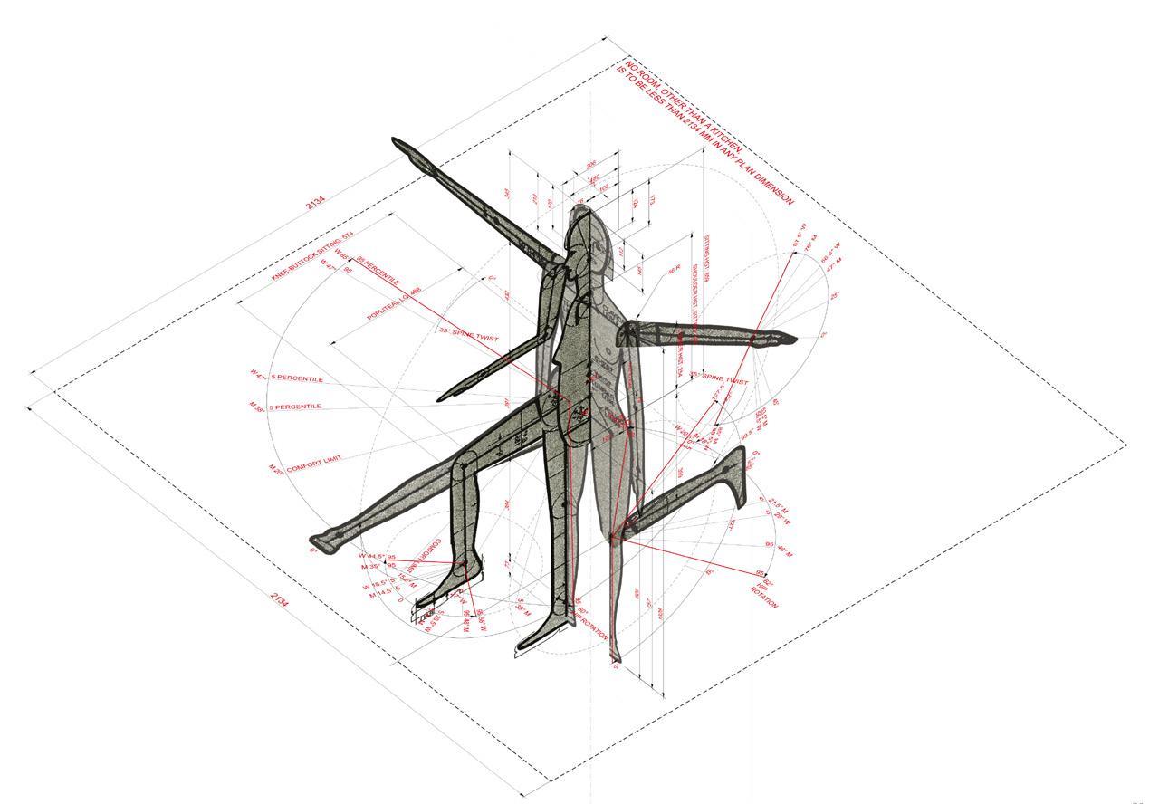
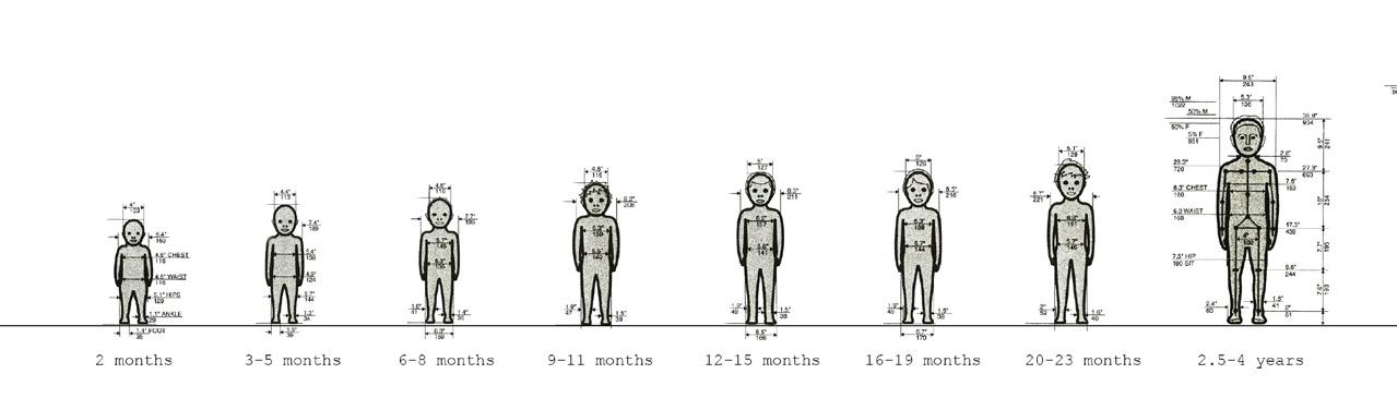
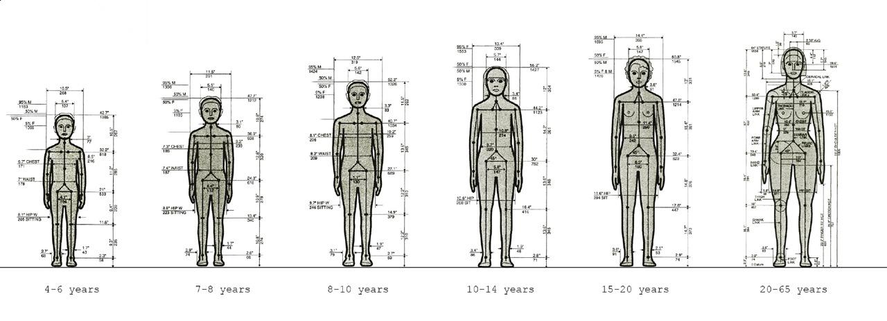
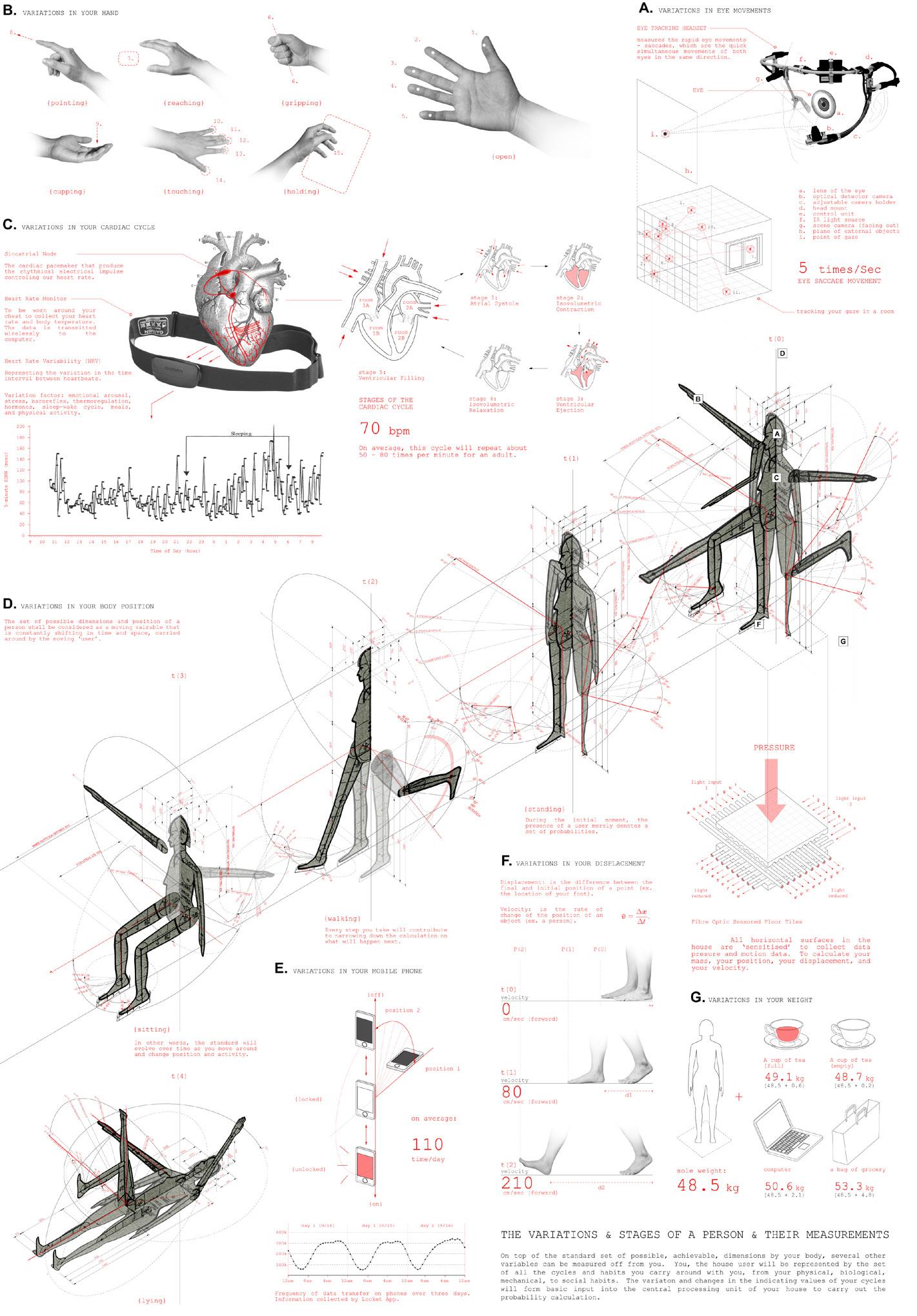

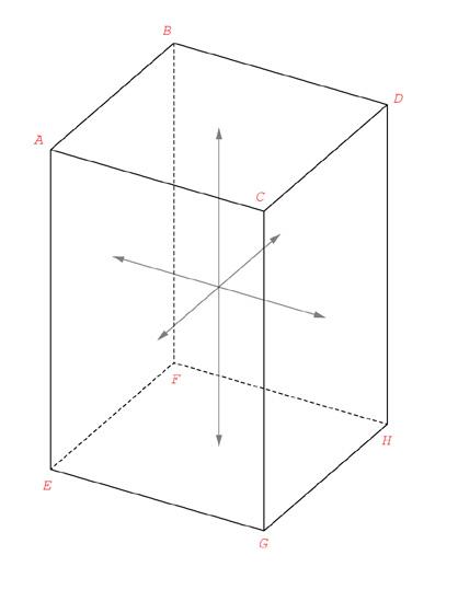
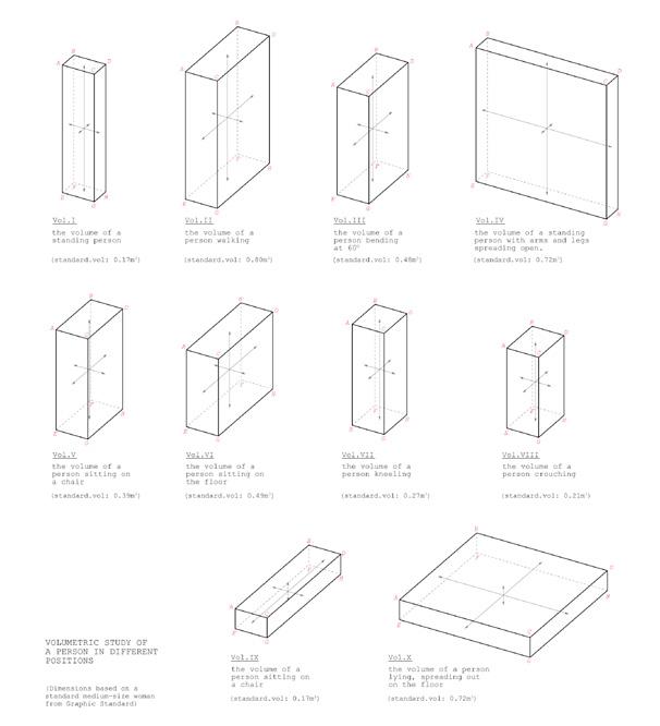


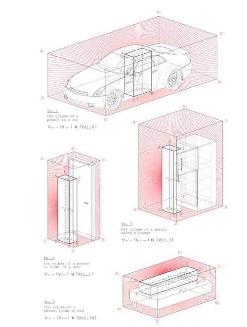
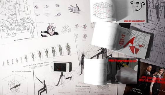
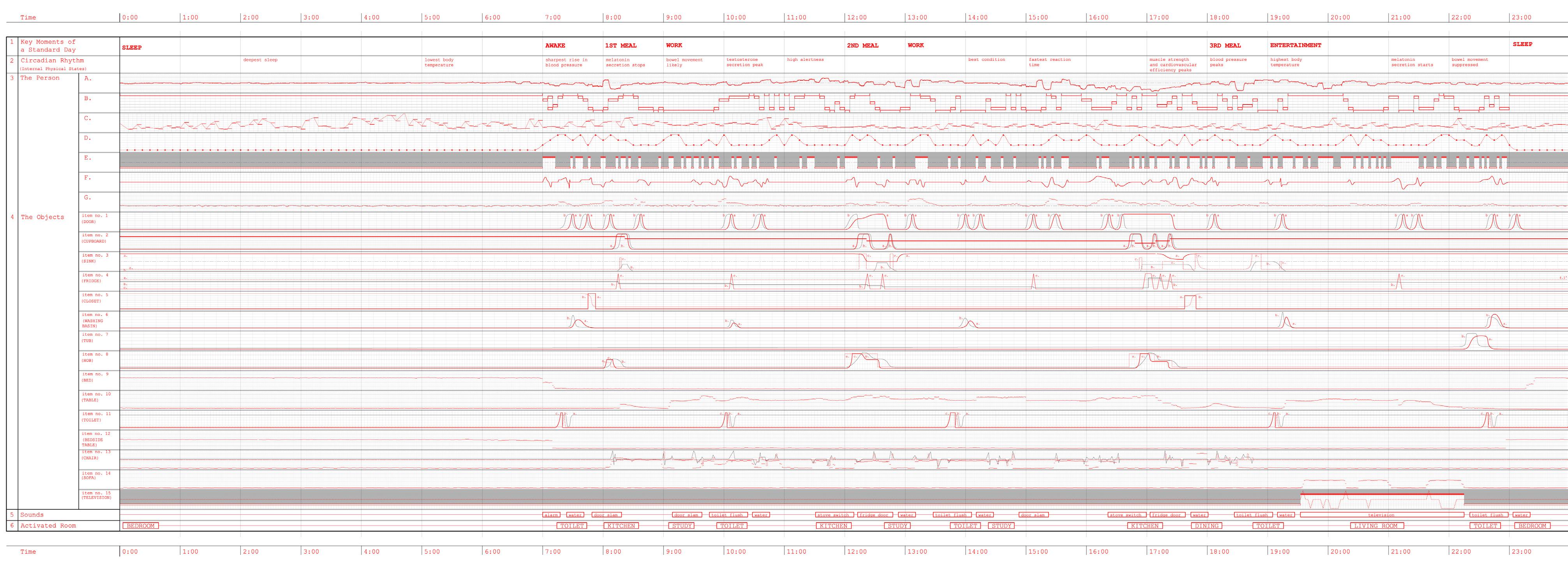
As the definition and organisation of a standard house are fundamentally set to meet the parameters of a standard user, my re-drawing of a standard house begins with the redrawing of a standard person. The current definition of a standard person is derived from statistical data on the measurements of our physical bodies. However, bodily dimensions are not the only system upon which we can define an individual. We live in a world where our activities and living patterns can now be constantly measured and recorded. This behaviometric data provides an alternative definition of an individual. Furthermore, by establishing the relationships between objects in the house and the individual’s
pattern, we can translate the individual’s behaviometric pattern into a
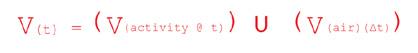
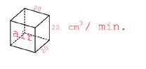
in the form of volumetric
over time.
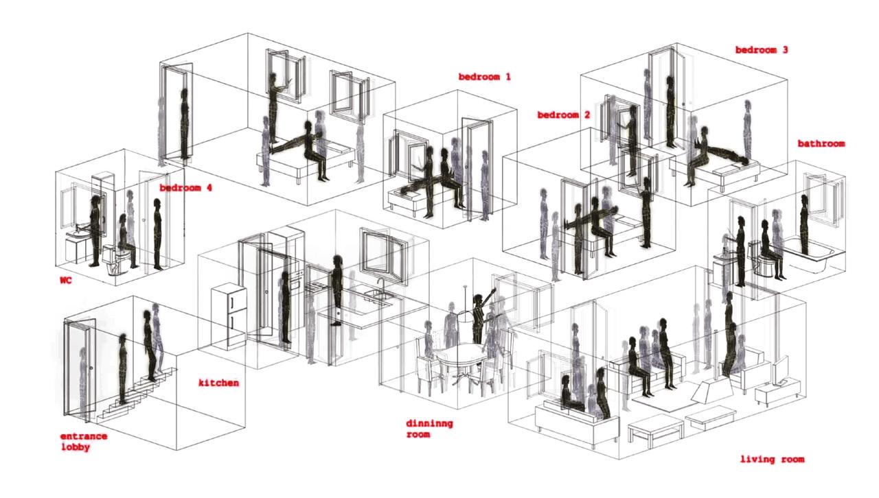
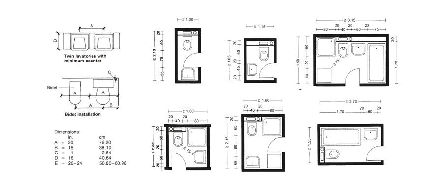
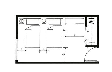
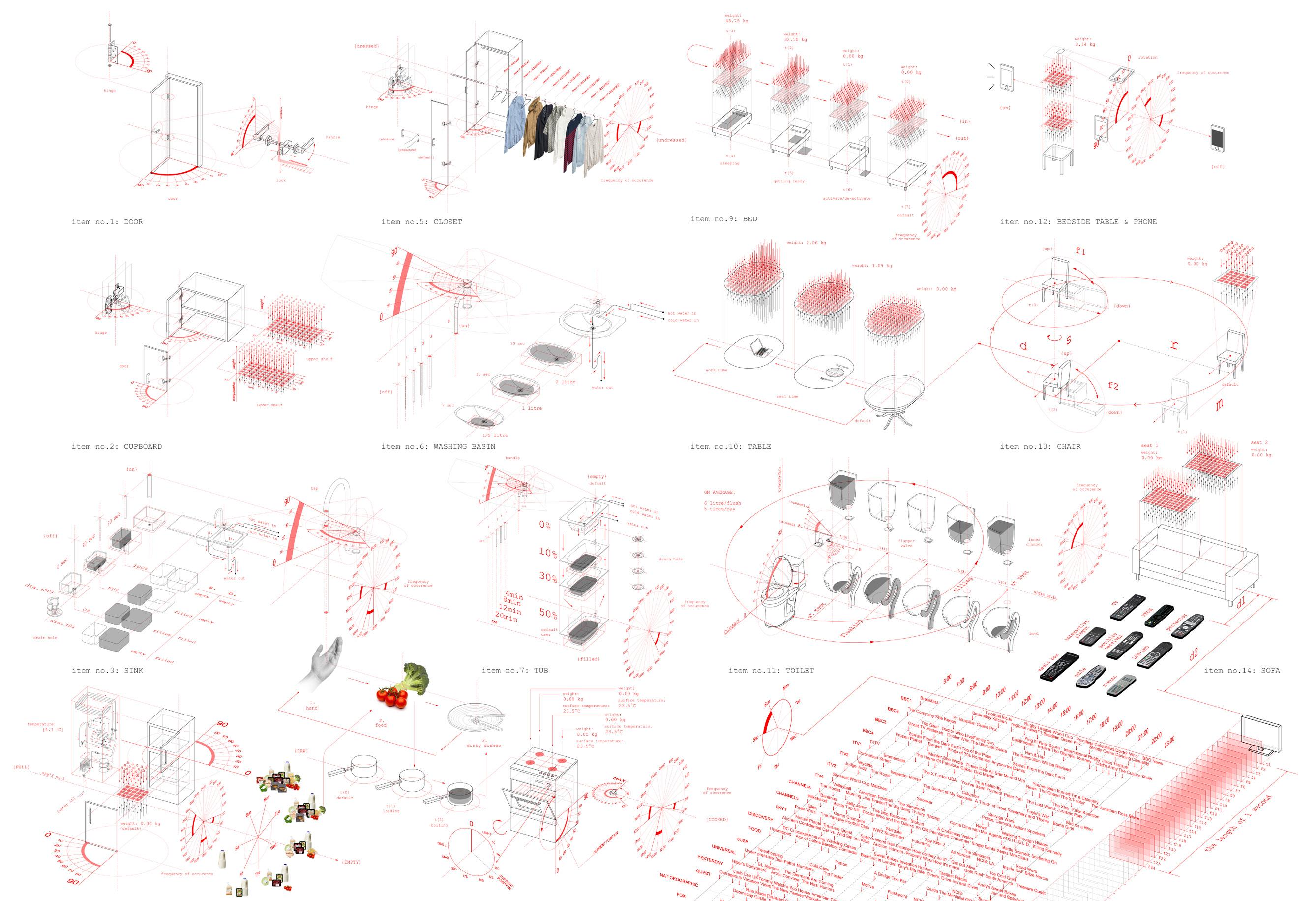
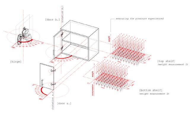
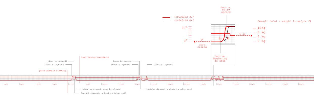
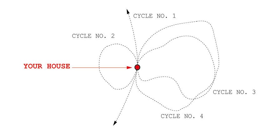
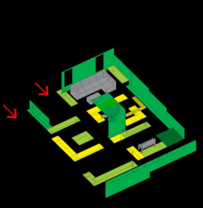
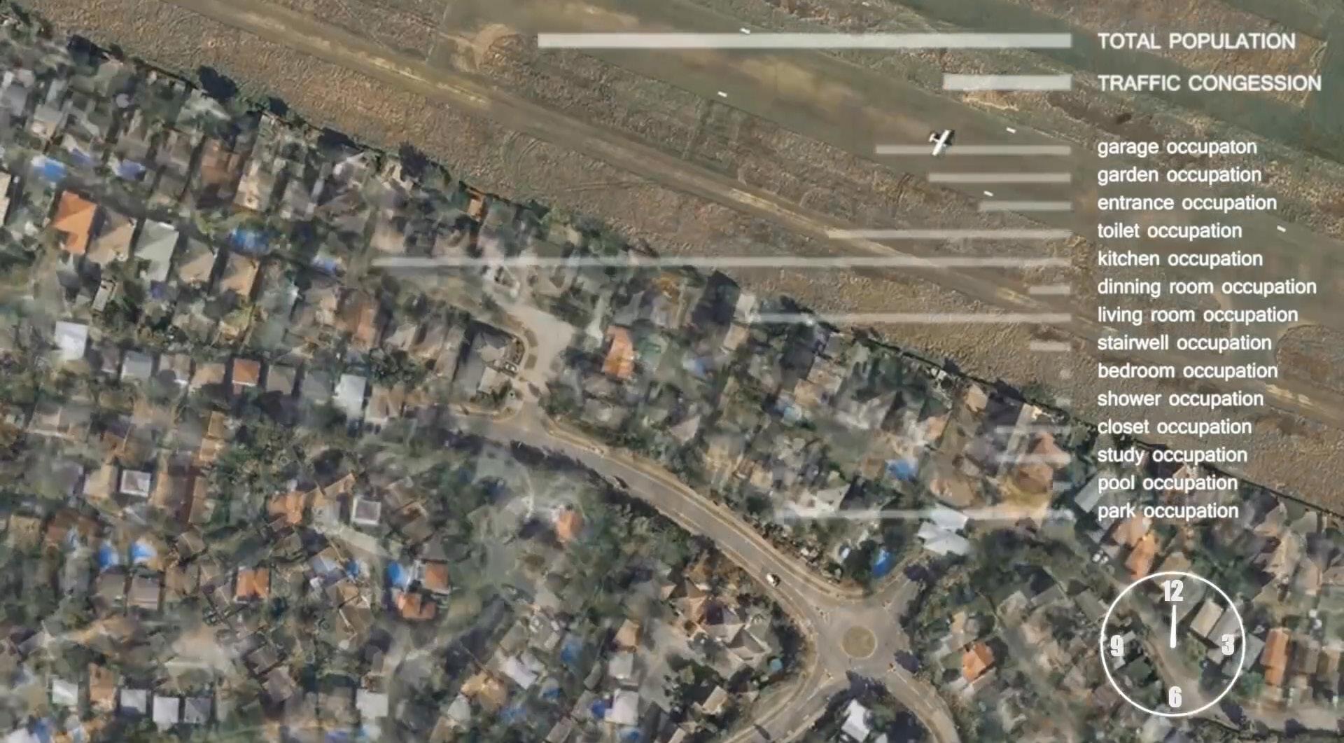
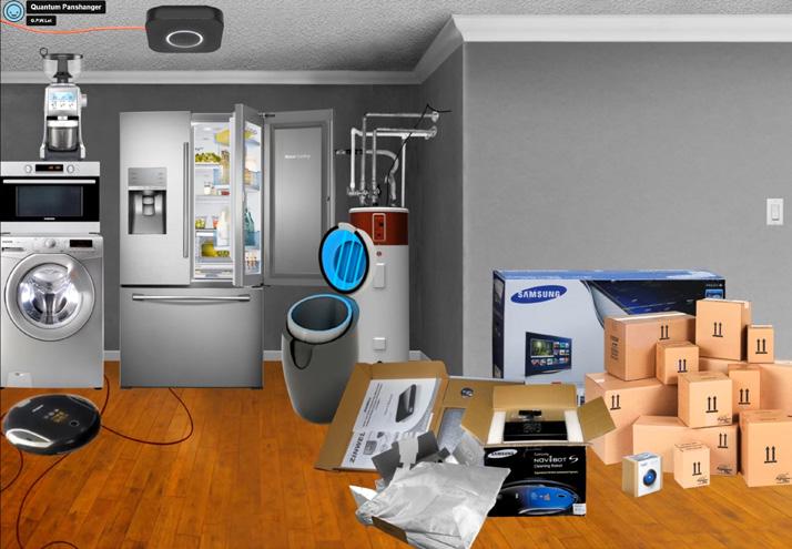
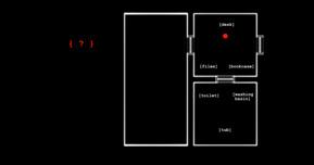
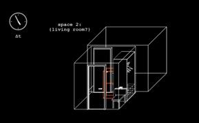
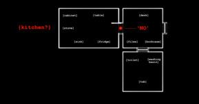
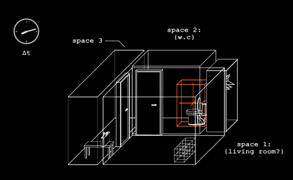
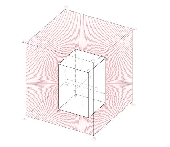
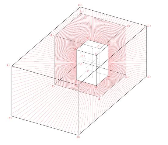
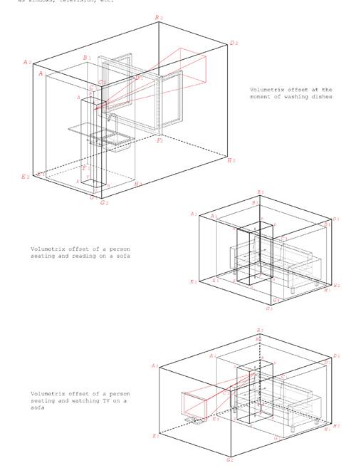
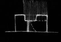
The current definition of a standard house is based on the set of rooms it contains. The spatial requirements are governed by the standard dimensions of these rooms, which are based on statistical measurements of a standard person and the typical objects found within each room. The layout of the current standard house assumes all rooms are occupied at all times. However, if we were to re-draw the standard house based on the user’s activities, a very different spatial manifestation would emerge. A map of the user’s activities can be traced through the fluctuations experienced within the house, from the rotation frequency of doors to the changes in weight on various horizontal surfaces.
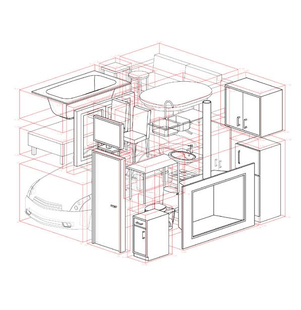
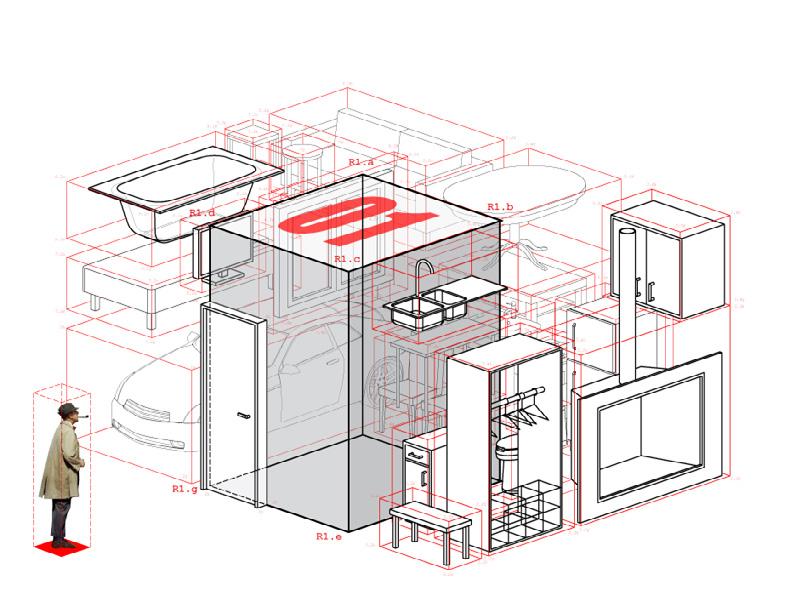
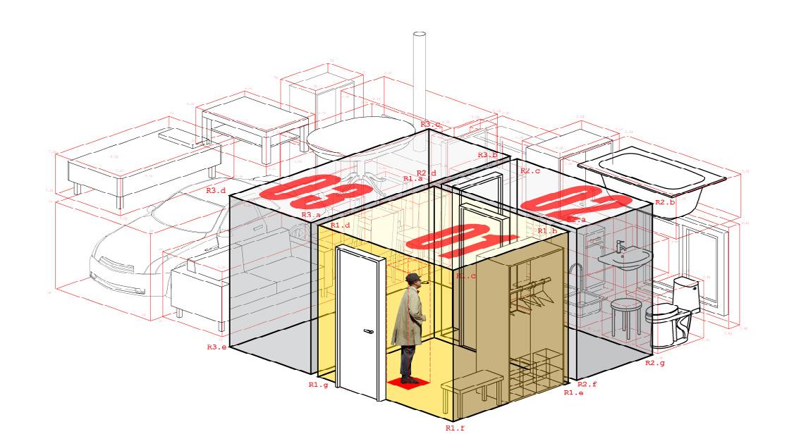
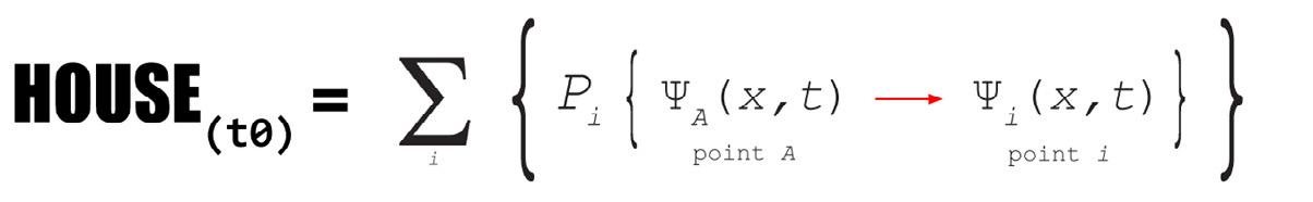
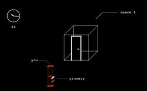
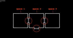
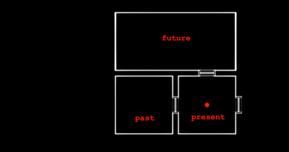
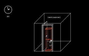
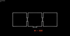
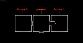
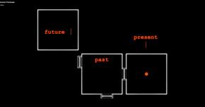
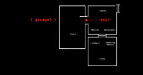
This alternative standard house, referred to as a ‘quatamic house’, is defined by the total volume of all the objects it contains, the users within the house, and the volumetric offsets of the rooms engaged. The plan of this house will be encoded in the form of a chart, recording the established behavioural patterns of its objects and users. When engaged, this house will expand to contain three rooms, representing the ‘past’, the ‘present’, and the ‘future’ of the user’s activities. The ‘past’ and the ‘present’ are determined, while the ‘future’ is calculated based on probabilities established by past events. Fluctuating between these three states and taking feedback from the user’s reactions, this house will constantly learn and relearn the shifts in the user’s behaviour and adapt its future responses accordingly.
2013 FOURTH YEAR PROJECT (AA SCHOOL OF ARCHITECTURE)
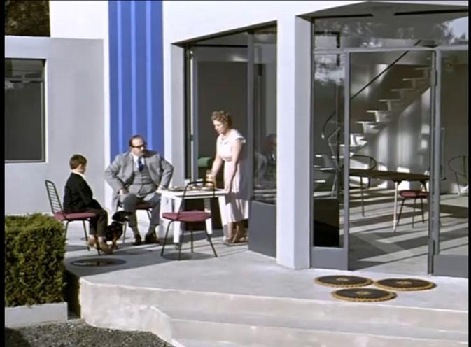
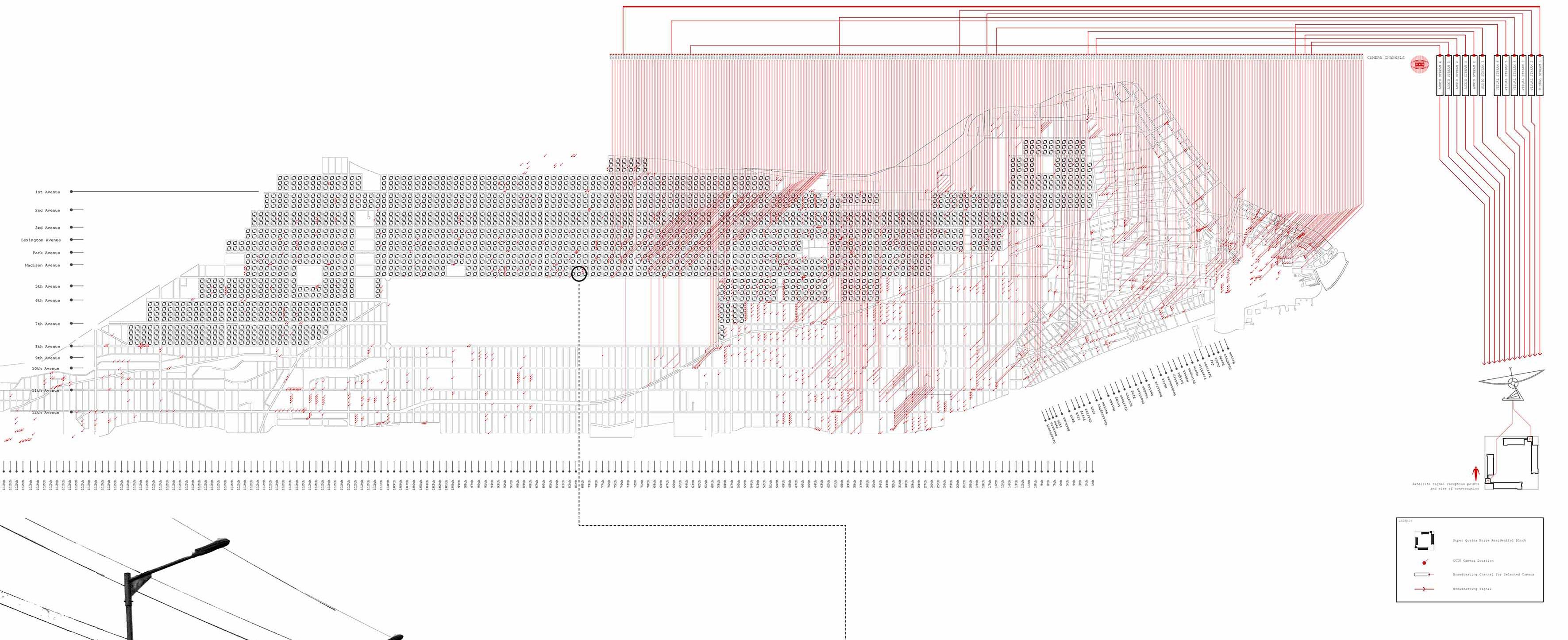
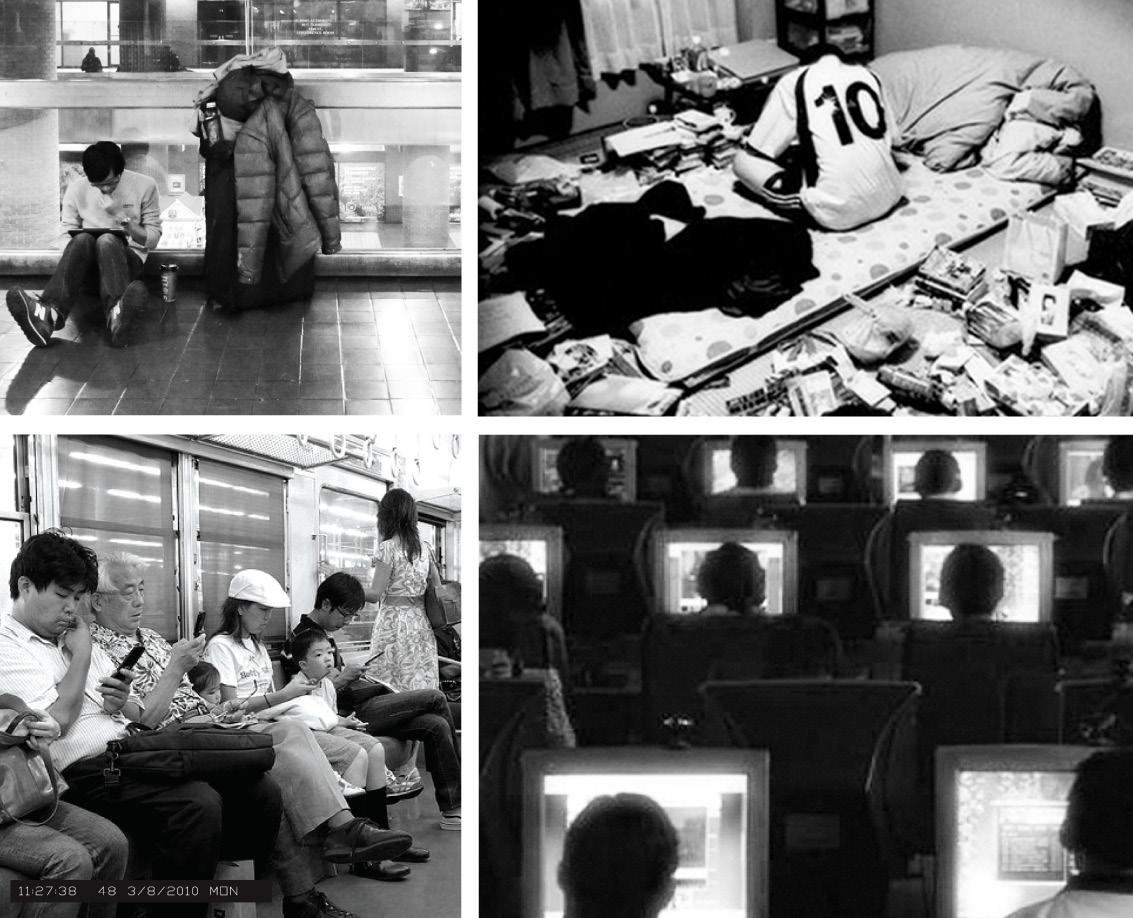
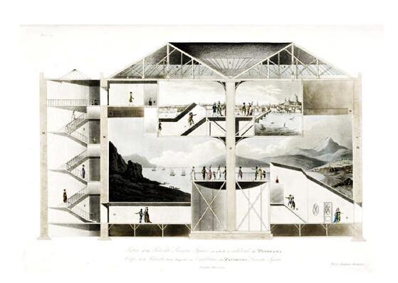
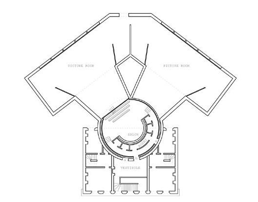
This project explores the topic of human communication (or the lack thereof) and architecture as a form of communication device. By situating the site within a satirical, fictional dimension, this project examines metaphorical architecture as a means to question and challenge the absurdity within our own reality.
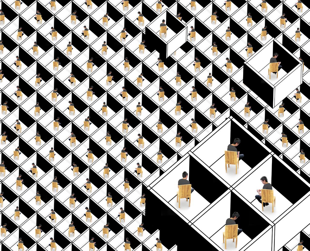


ARCHITECTURE FOR COMMUNICATIONS
HOW SHOULD WE EXPERIENCE EACH OTHER? CONVERSATION?
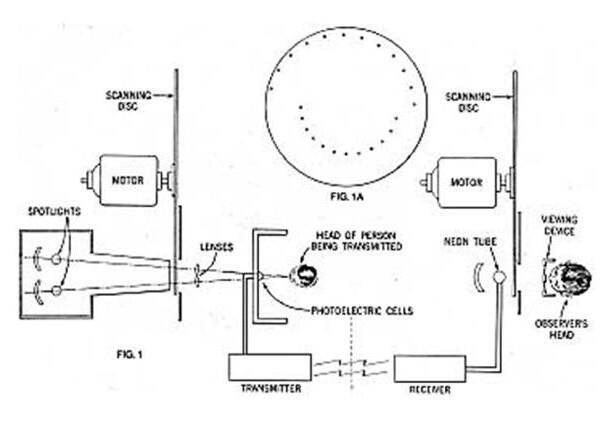
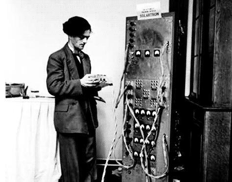
Looking at the phenomenon of collective individualism enabled by our portable devices, which connect us to a world of digital information, this project explores communication infrastructure that conveys a different kind of knowledge: the subjective, physical sensation of another human being. Continuing the path of using architectural setups as a means to create collective understanding of a single event through structured perspectives, this project explores architecture that acts as an interface between the subjective worlds of its participants. Metaphoric architecture is adopted as a method to frame a discussion on a social issue.
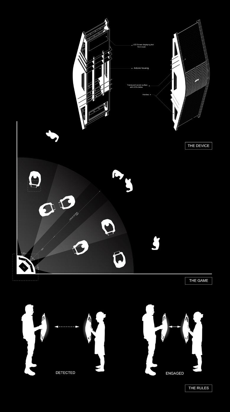
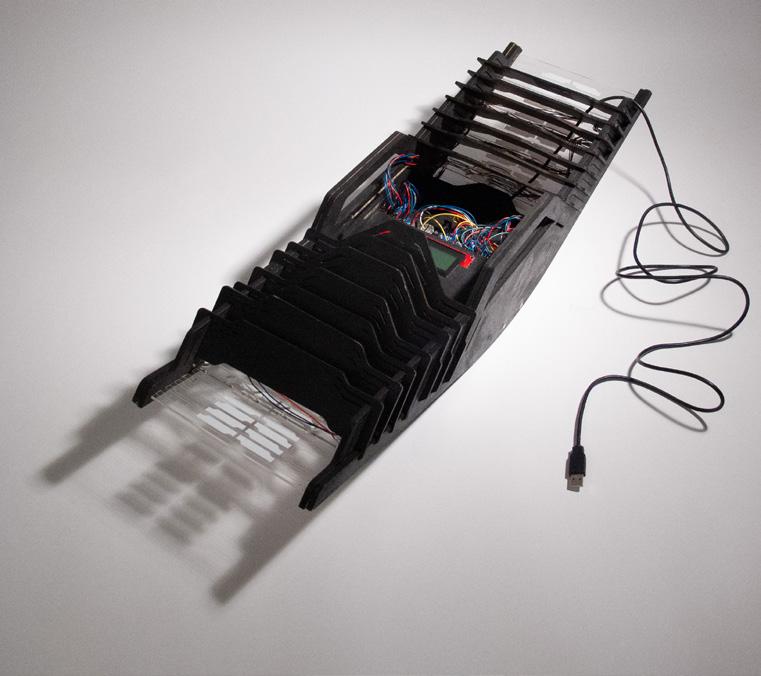
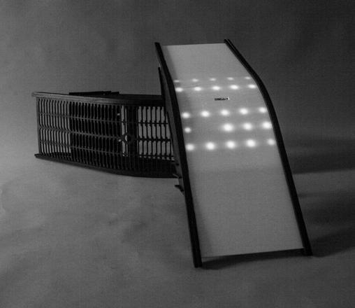
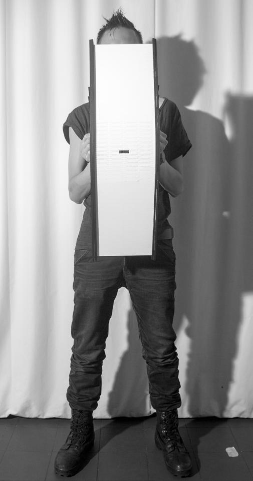
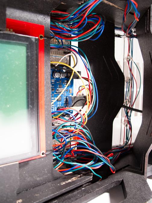
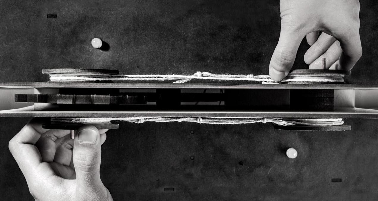
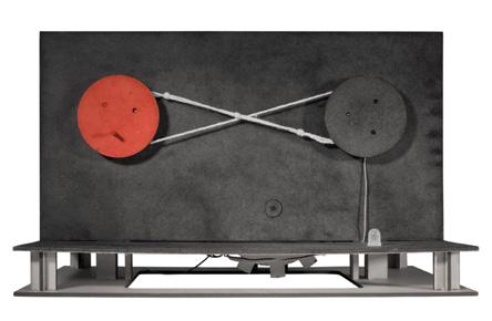

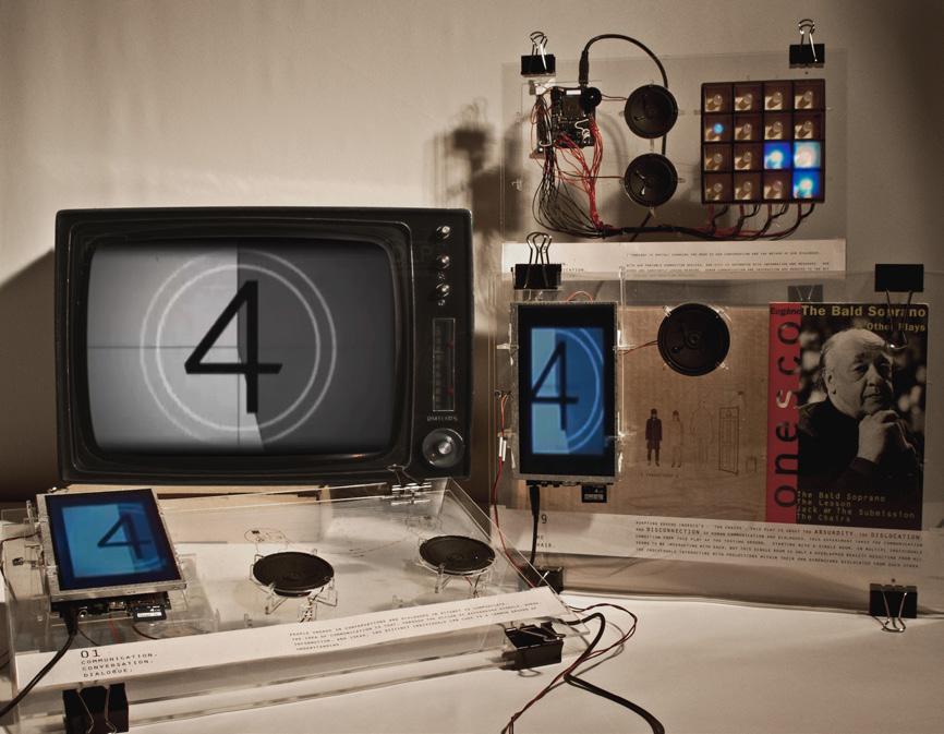

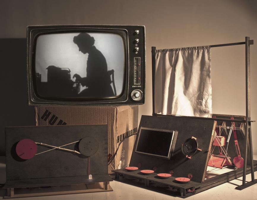
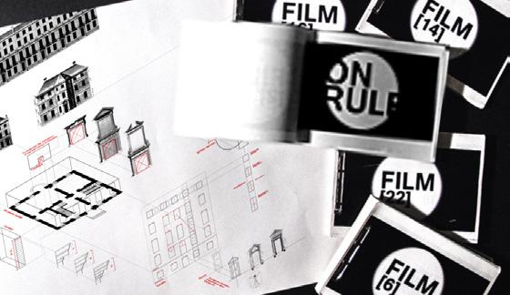
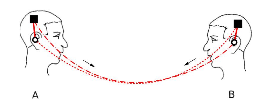
Exploring the structuring of human communication through an interactive game, the Tongue is a device that shields the players from each other. Communication is established by negotiating with another player to pair the devices and control the relative speed of messages being displayed on an internal screen. Moving away from devices that communicate digitally to explore the dimension of physical sensations communicated through analog means, the Toys were created as artefacts from a fictional world controlled by a totalitarian government. Propaganda films were created to convey the government’s philosophy on communication and to educate its citizens on the idea of ‘experiential conversation’.
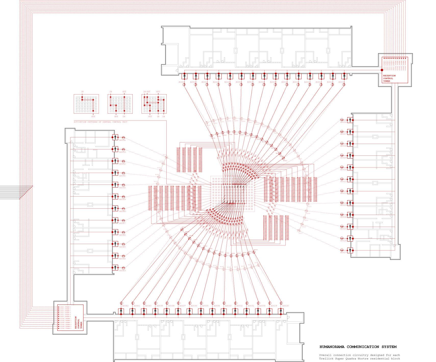
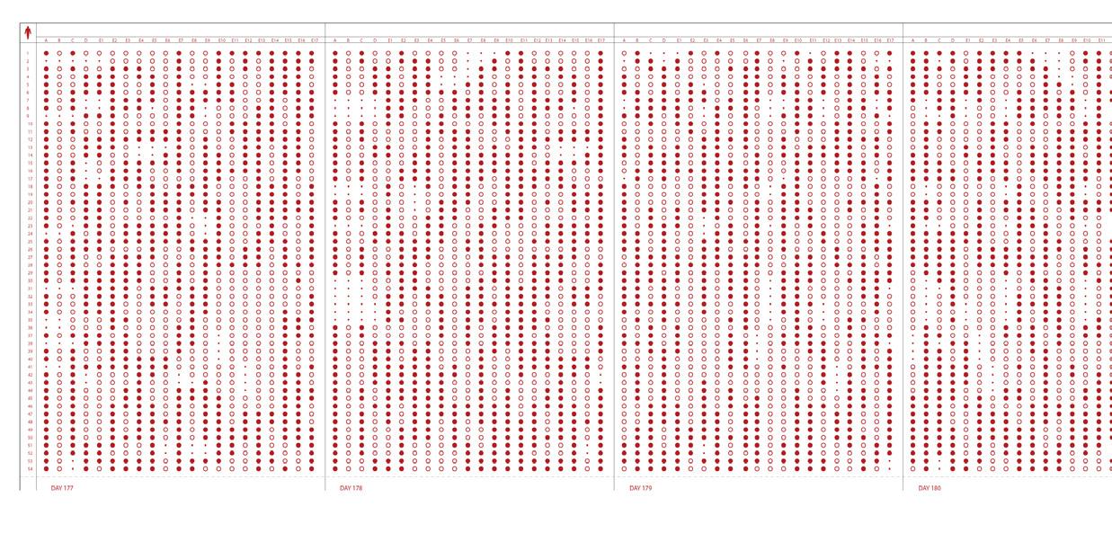
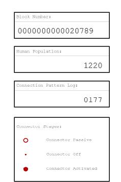


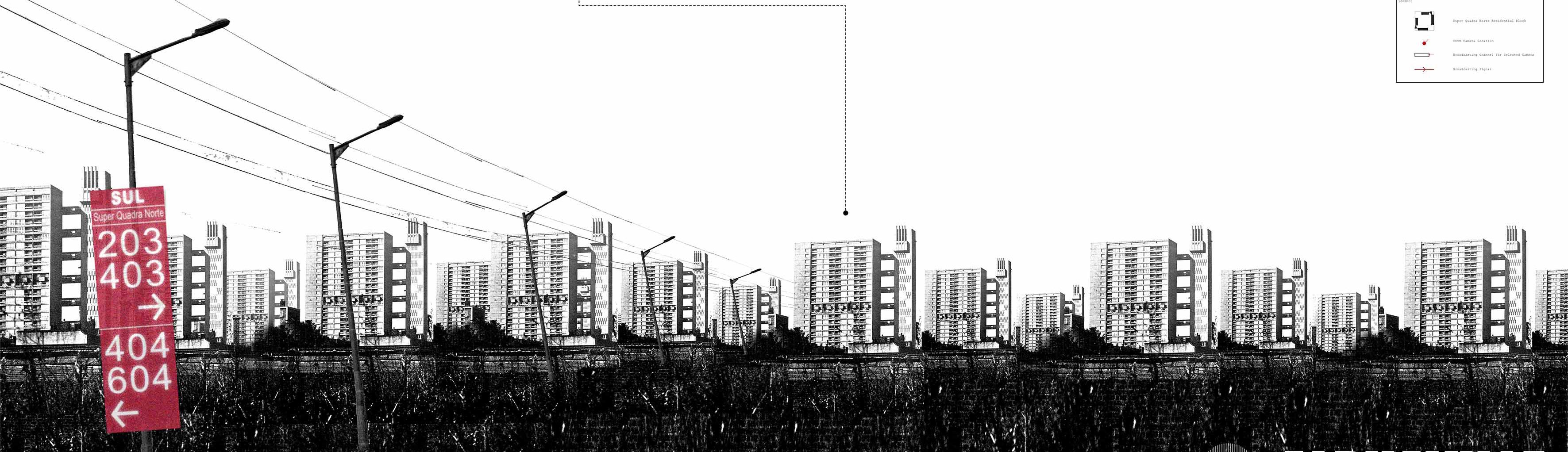
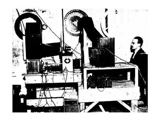
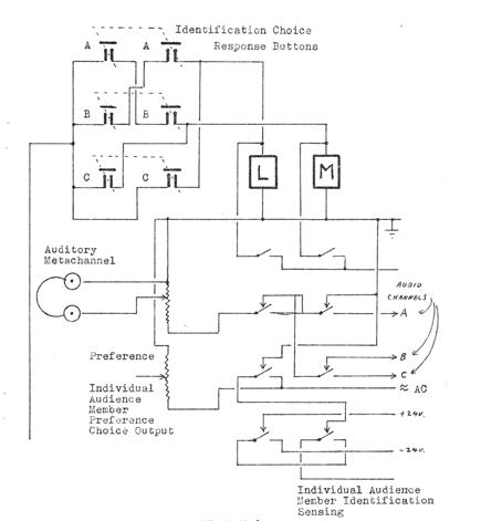
In the city of Alphaville, each individual now lives in their own separate pod, with daily life carried out in the virtual world. To remind its citizens of the reality of other human beings, the government mandates participation in a daily collective event where citizens engage in an hour of experiential conversation with another person in the conversation chamber of a mega analog interaction infrastructure known as the Humanorama. However, as the concepts of love and emotion are not permitted by the government, the contacts are established indirectly and anonymously, with participants blinded to the identity of the person they are engaging with.
2009 FOURTH YEAR PROJECT (UNIVERSITY OF WATERLOO)
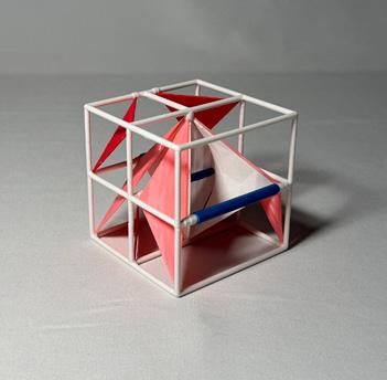
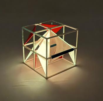
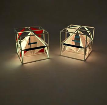
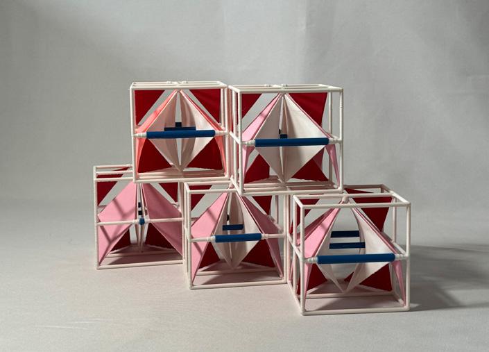
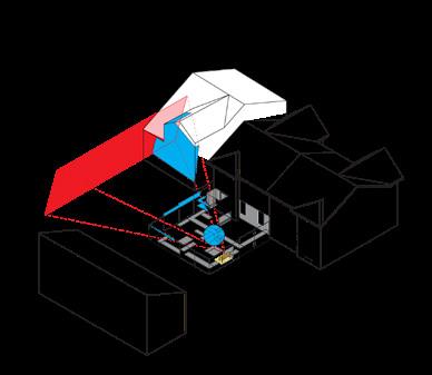
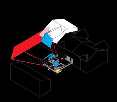
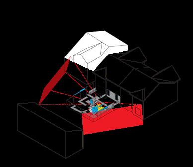
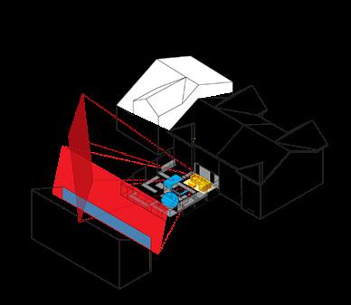
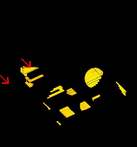
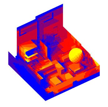
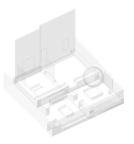
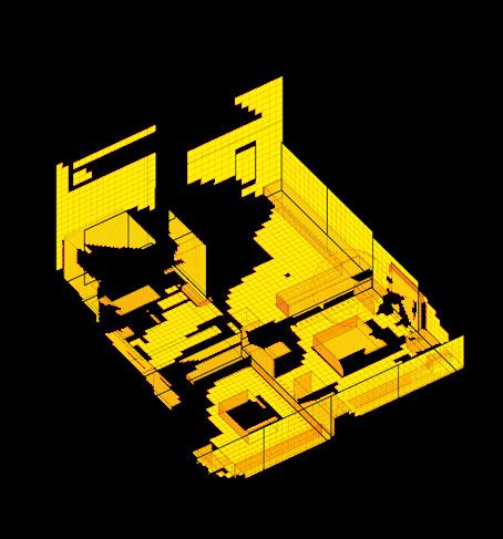
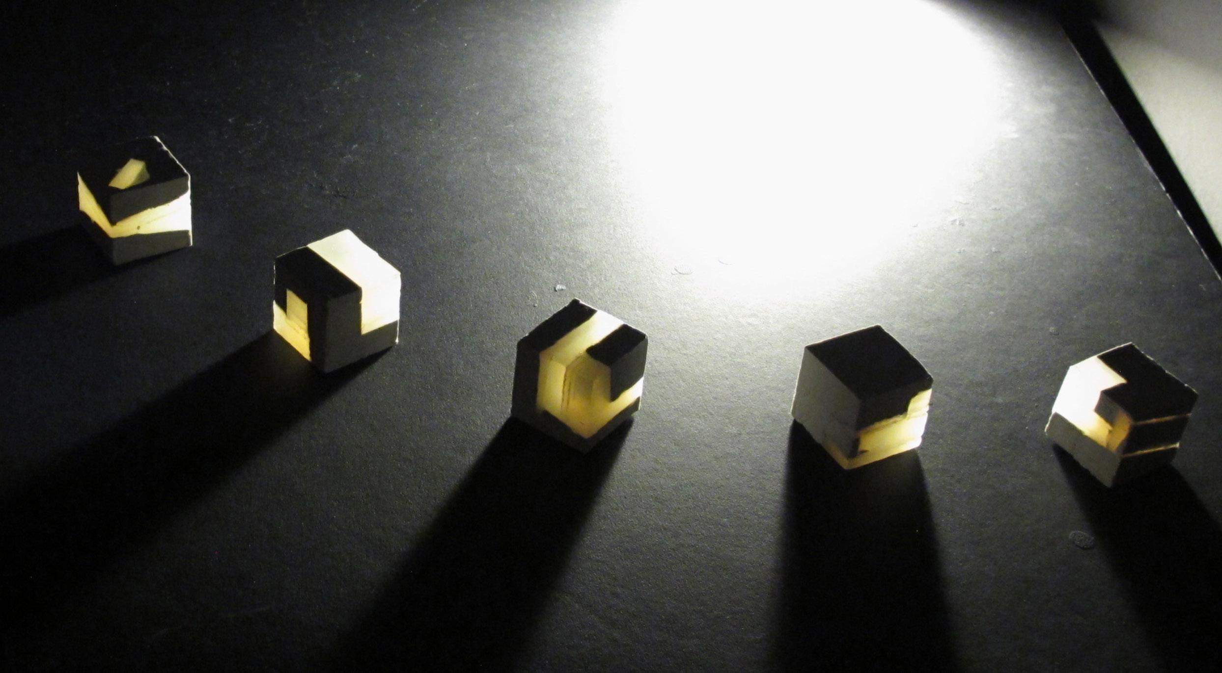
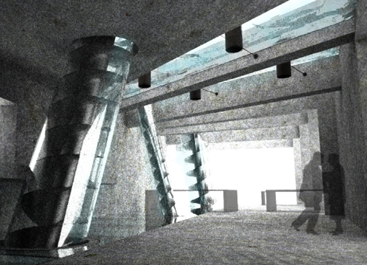
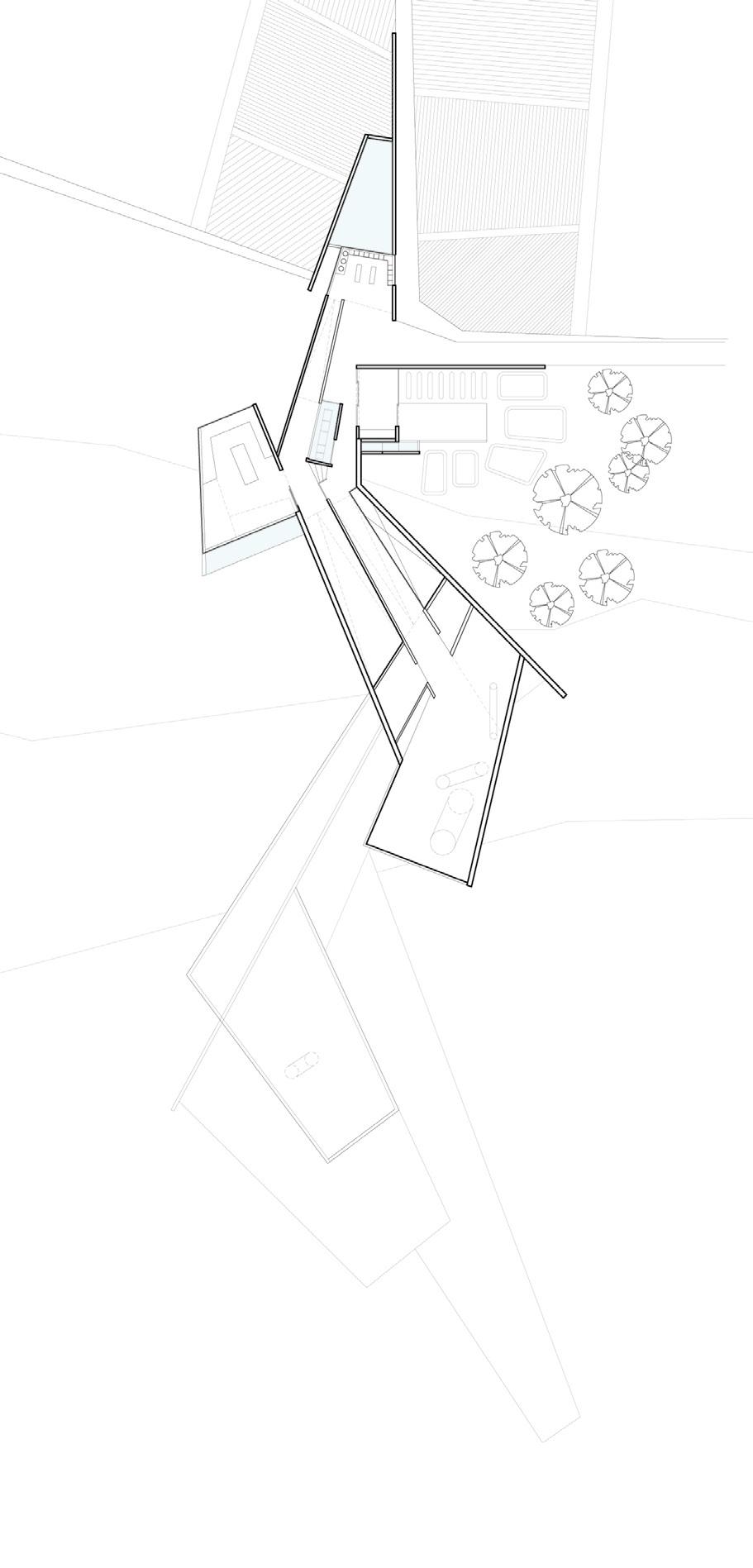
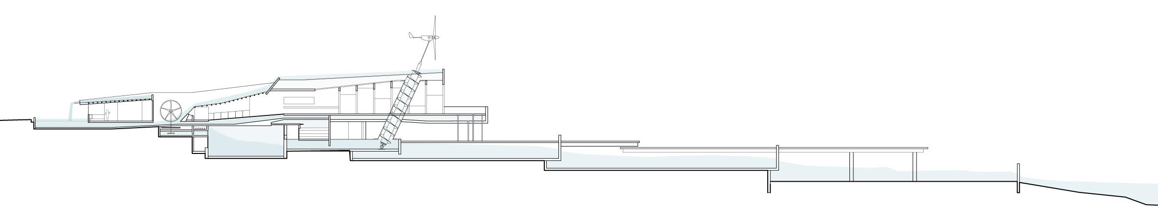
Underlying this project is the intention to incorporate sunlight as an integral component of the building envelope and as part of its building material, rather than solely as an external environmental factor to be protected against.
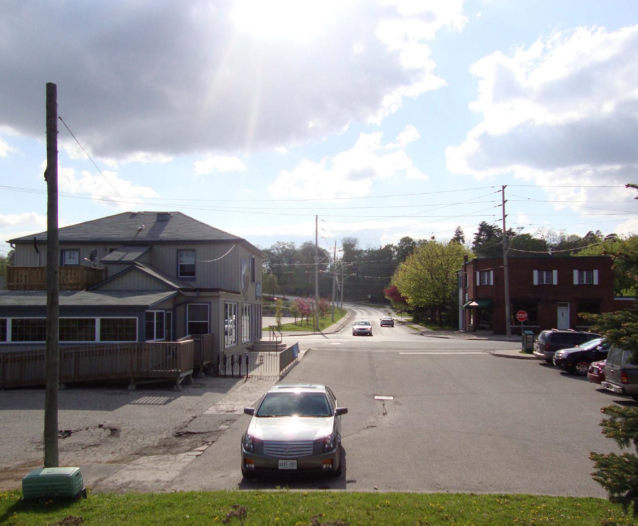


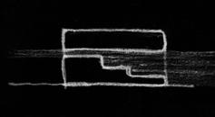
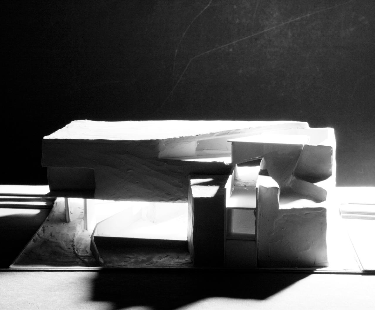
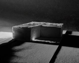
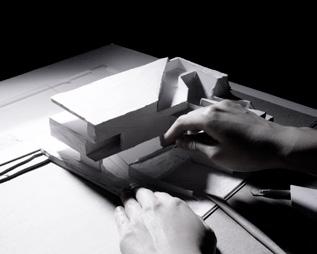
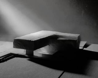
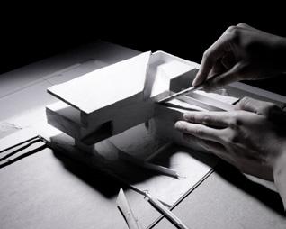
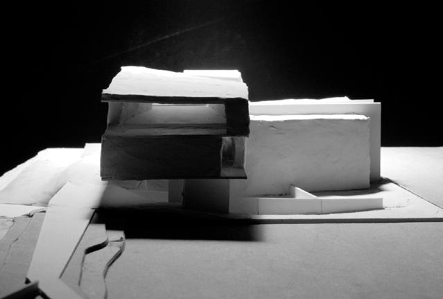
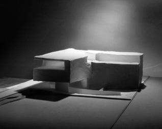
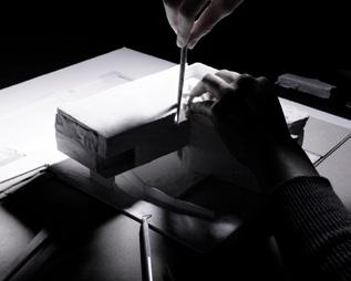
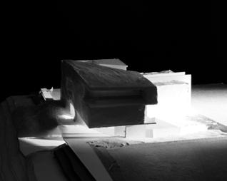
Inspired by the blinding sun conditions at the site, in a landscape otherwise lacking in defining context, the intention is to create a building that provides contextual experiences for the passing observers and transforms with the sun throughout the day. A sun-filter camera was created to distil the abstract quality of the sun on site from other surrounding contexts and map the light quantitatively, treating it as an object by itself. To translate the quality and direction of the captured sunlight into a formal composition, negative spaces were carved out of a solid mass to create tunnels that would be filled with sunlight at different times of the day.
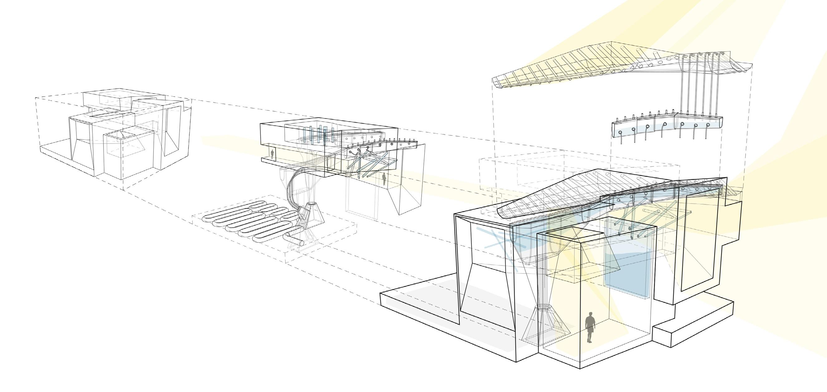
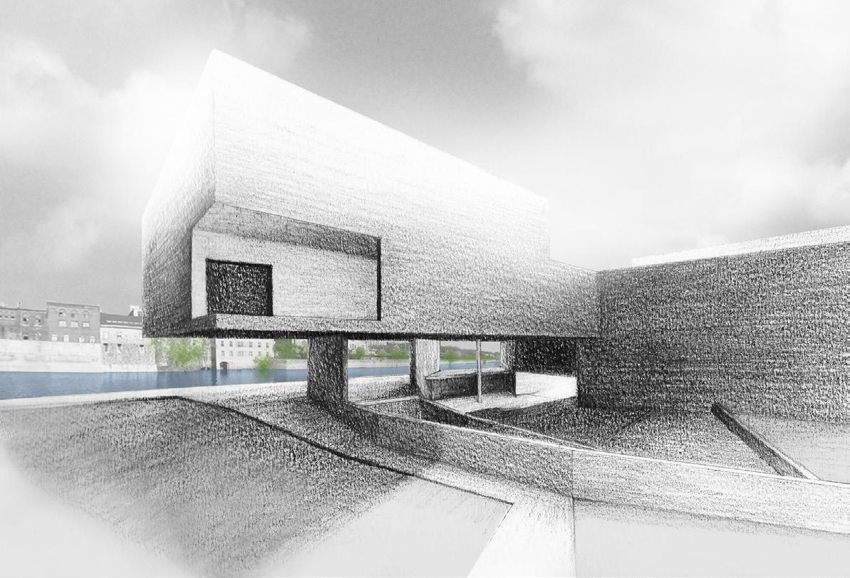
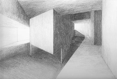
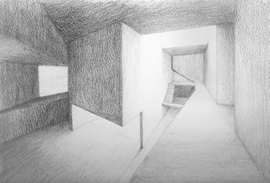
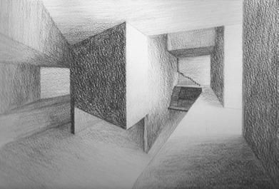
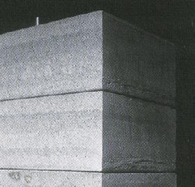
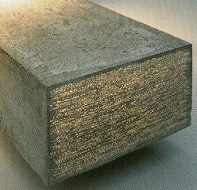

The sun is captured in two ways: experientially and functionally. As the sun moves into different positions relative to the building, different pockets of the building would light up. Working together with a building envelope composed of transparent concrete bricks that allows light to penetrate, the building would transform over the day, creating a changing experience for observers both internally and externally. Functionally, a series of mechanical contraptions are integrated spatially into the building. The intention is to utilise the sun’s heat to deliver 80% of its heating and cooling functions directly, using a mechanical system based on the principle of absorption and desorption of lithium bromide dissolved in water to generate a cooling effect.
2006 SECOND YEAR PROJECT (UNIVERSITY OF WATERLOO)
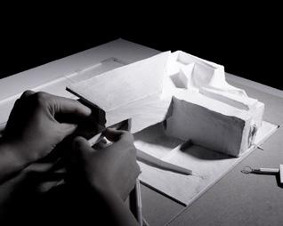
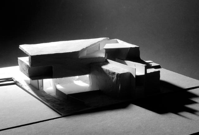
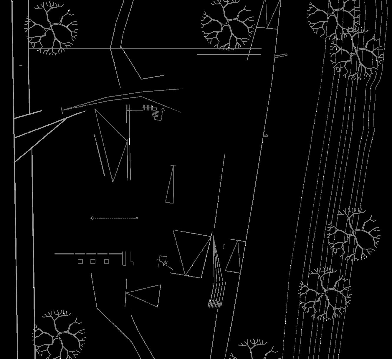
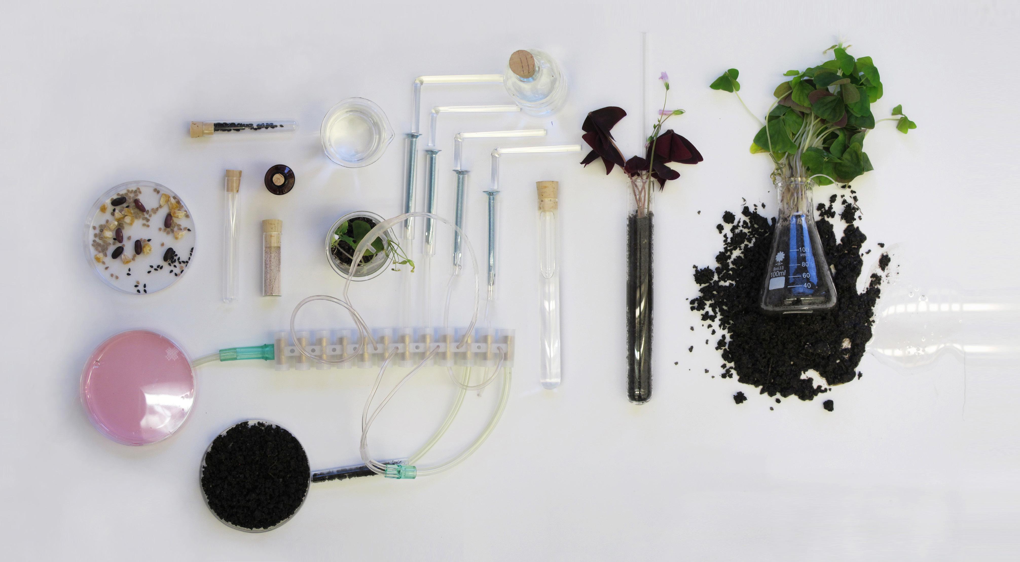
This project explores the idea of architecture which, in addition to fulfilling its spatial requirements for its occupants, also serves as a self-sufficient infrastructure that cleans up after itself and processes its own wastewater.
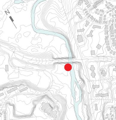
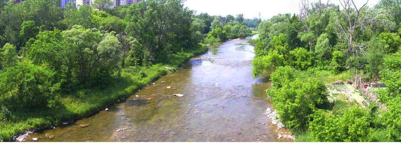
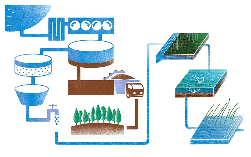
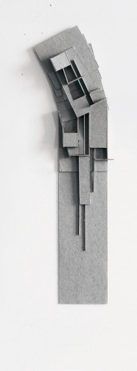
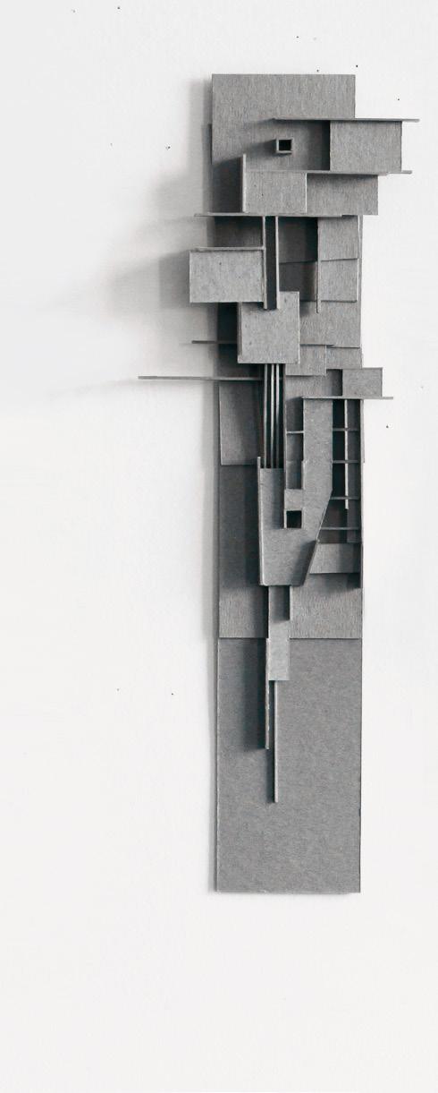
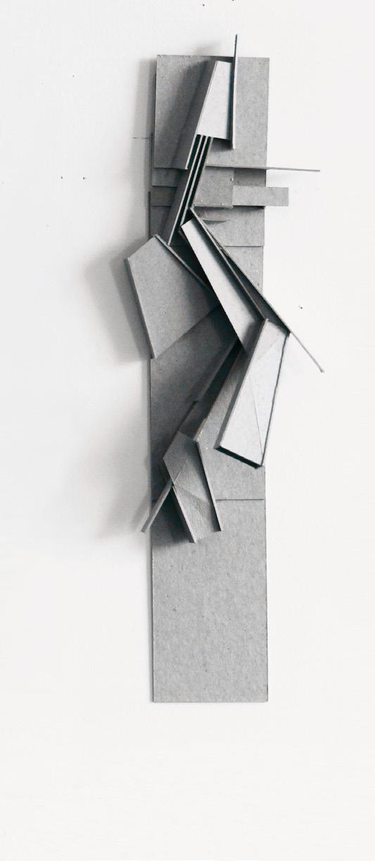
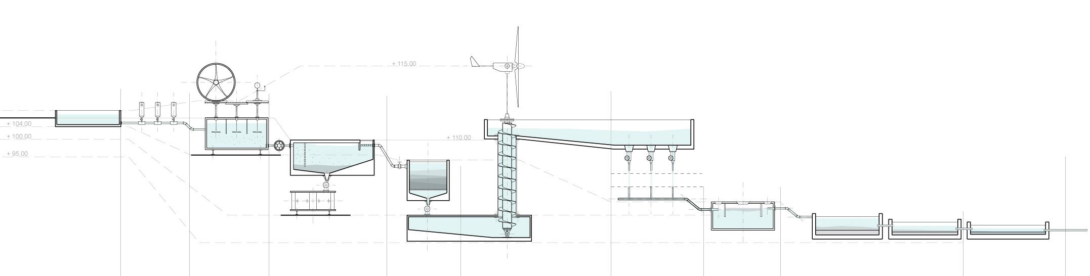
The brief is for a new agricultural community centre at a site along the Humber River in Ontario. The activities of an agricultural centre involve the consumption of a large quantity of water. Therefore, the project aims to incorporate water treatment as an integral part of the building’s program use. The form of the building is driven by the organisational principle of entwining the activities of water with those of people, as well as the level changes required to circulate the water throughout the building to perform the treatment process before it is released back to the river.
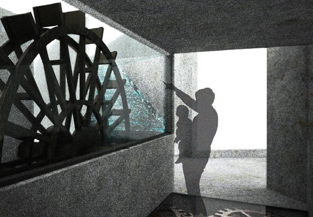
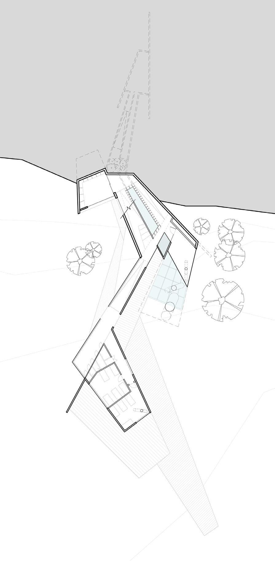
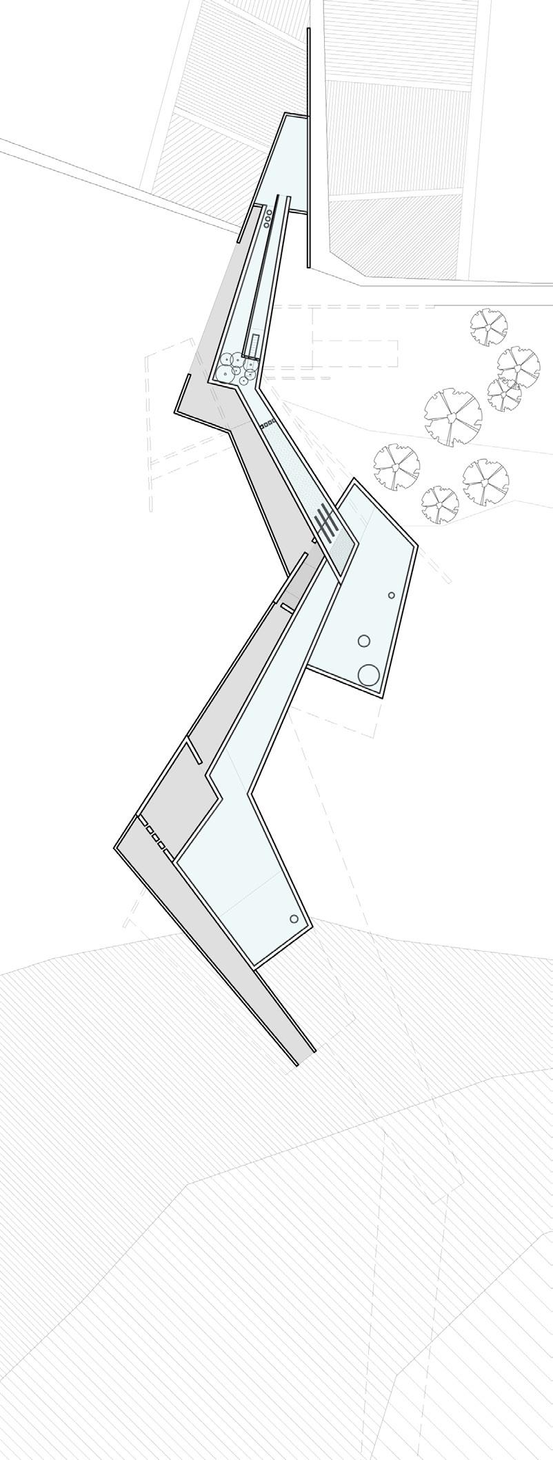
The activity of water, driven by gravity, is mapped out as a continuous slope that runs through the twisting form of the building, with different activities of the agricultural centre wrapping around it. At intersection points, moments of the water treatment mechanism and the activity of the water itself are revealed to users and become part of the space, reminding them of the parallel life of the building’s other occupants.

of
The outline application is comprised of a framework of documents which establish a set of design rules and parameters against which future Reserved Matters Applications will be assessed. It builds in flexibility to enable RMAs to respond to changing social and economic contexts.
Outline Application
The remaining landscaping and access in addition to the design of all buildings will be subject to approval at the Reserved Matters Applications (RMA) stage.
Design control documents are submitted for approval as part of the outline application. The mandatory aspects of the Design Code will be conditioned and RMAs will need to comply with them.
1.2.2
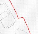
All future RMAs must demonstrate conformity with the parameters, principles and control clauses set out in the design control documents (Figure 3). At each RMA stage, there will be opportunity to assess and consult the community on the detailed proposals.
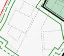
The in spatial and quantitative terms. This includes the extent of where the buildings should be set out on the scheme, maximum heights, site levels and the application boundary. The parameter plans are fixed, and the illustrative masterplan shows one way in which the scheme can be delivered within the parameters.
– The Development Specification sets out the design principles in quantitative terms. It prescribes the minimum and maximum quantums for the parameter plans, illustrative land uses, parking parameters and the tenure mix.
– The Design Code sets out the qualitative approach to the design of the scheme, including the mandatory rules, requirements and guidelines around architectural and landscape features such as appearance, materials, landscape, frontages, deviations and set-backs.
1.2.3 Supporting Application Documents
This document, the ‘Design and Access Statement’, sets out the masterplan design intent and principles, explaining the reasons for design decisions and how the design has evolved. The illustrative scheme is used throughout this document to explain the masterplan and demonstrate an approach to how the key design principles could be addressed.
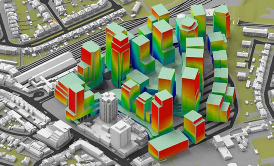
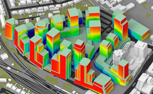

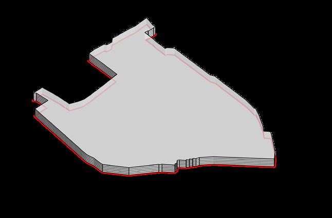
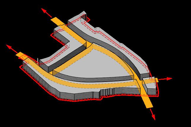
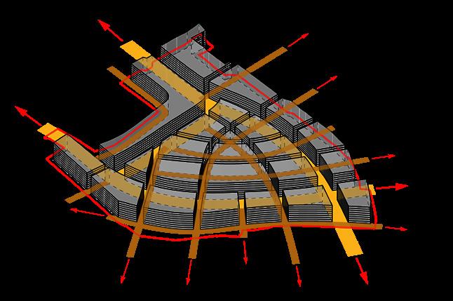
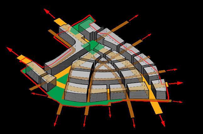
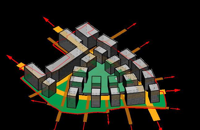
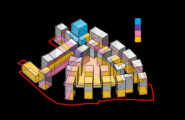
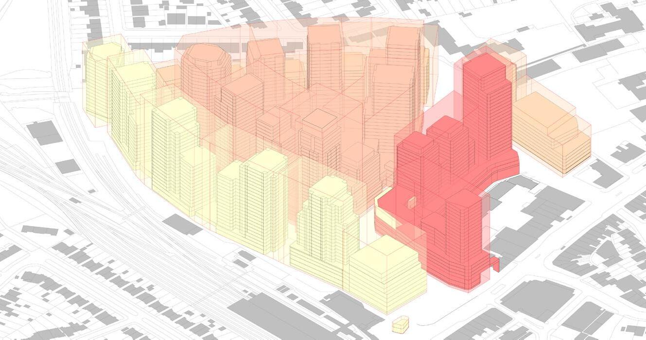
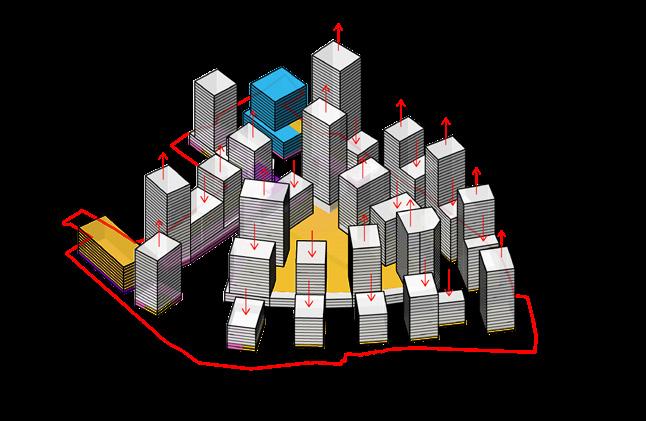
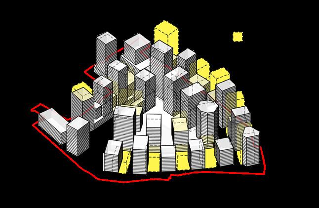
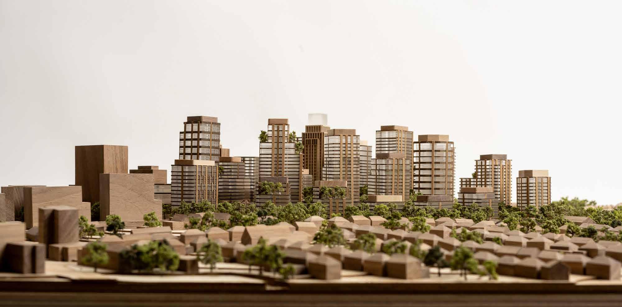
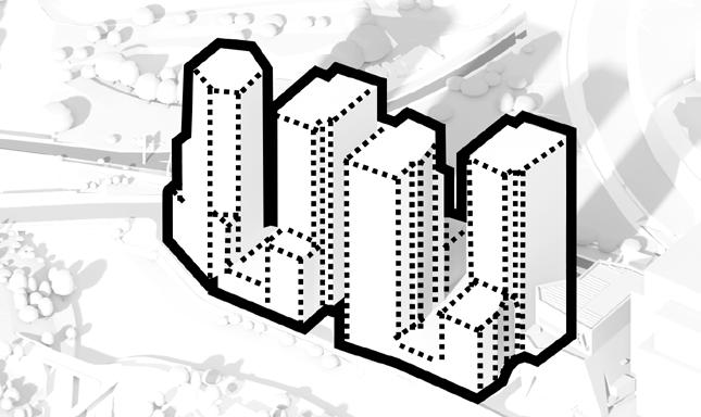
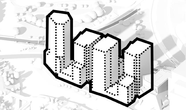
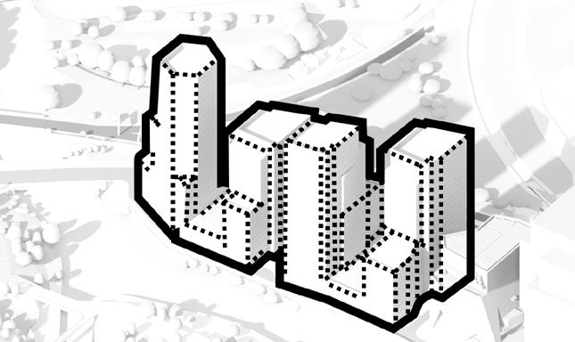
The proposal is to be submitted in the form of an Outline Application, with the goal to agree on the general design principles and maximum development parameters for the site. This includes arrangement on access and road connections, development plot sizes and locations, maximum quantum for each use and open parks, as well as maximum building heights. The massing optimisation study takes the London Plan’s allocation of 4,000+ homes for the site as the starting point. Maximum building heights required to achieve the allocated capacity are established after implementing all supporting infrastructures and uses. Final adjustments are made to the massing to meet the residential quality standards required. Following the optimisation
and
of


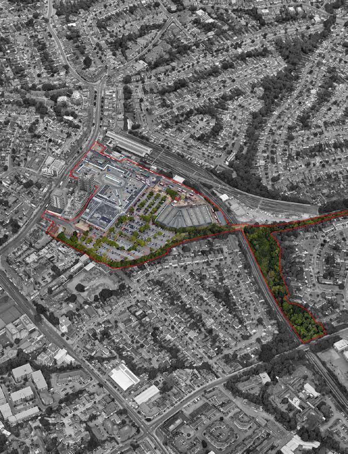
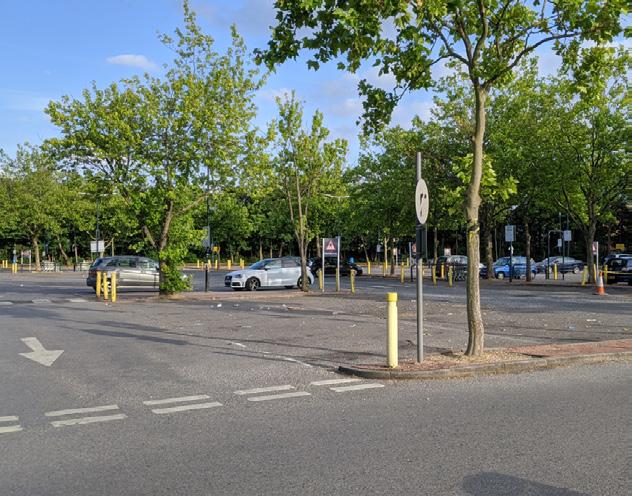
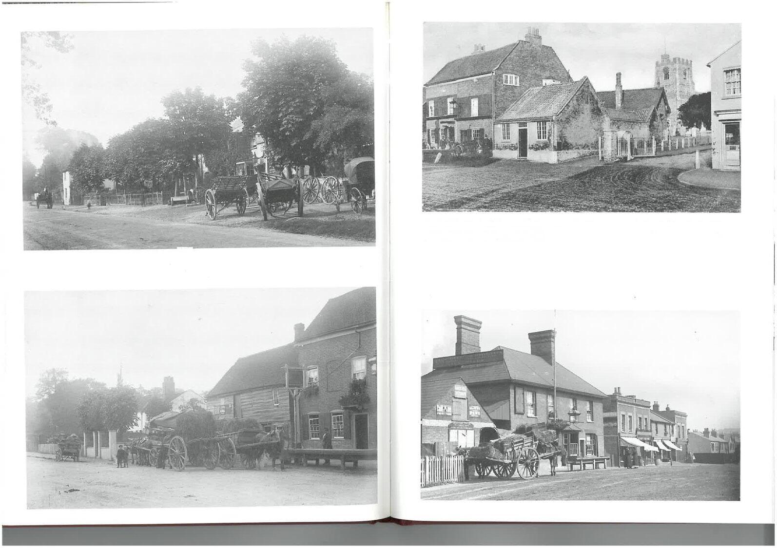
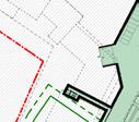
A set of key objectives was established early in the project's development which responded to the aspirations of the Edgware Growth Area SPD, site analysis and stakeholder consultation. These objectives have been consolidated into a vision for Edgware Town Centre.


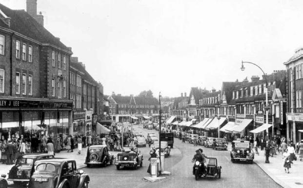
Enable the transition of the vehicledominated town centre into pedestrianfriendly public realm by modernising the transport interchange and introducing new public realm and greenery. Enhance and enrich the retail experience of Station Road by introducing diverse and complementary retail and commercial offers.
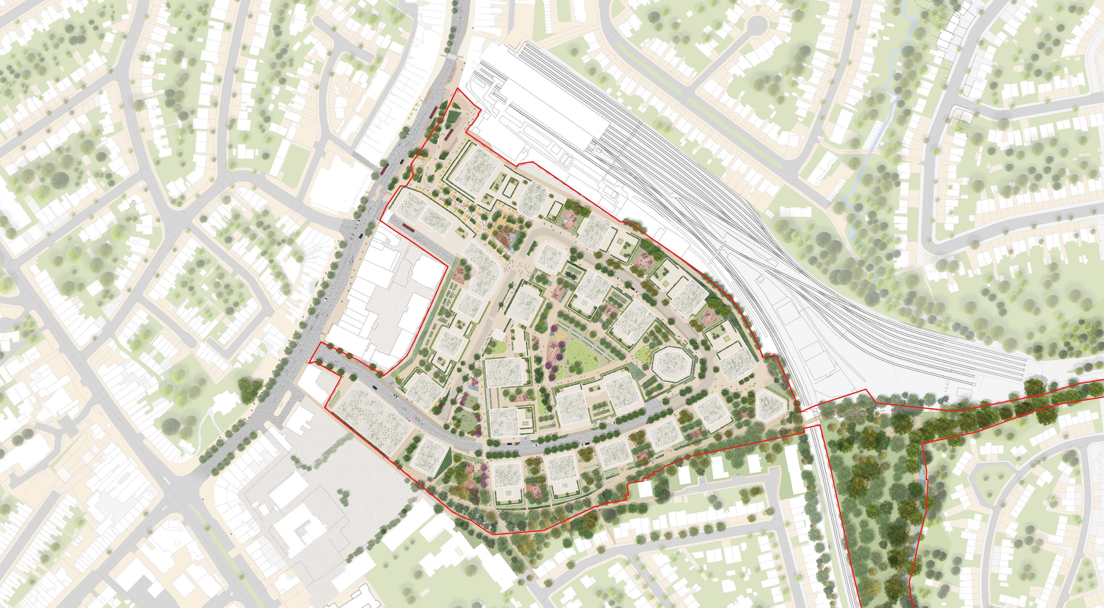
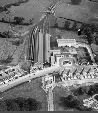
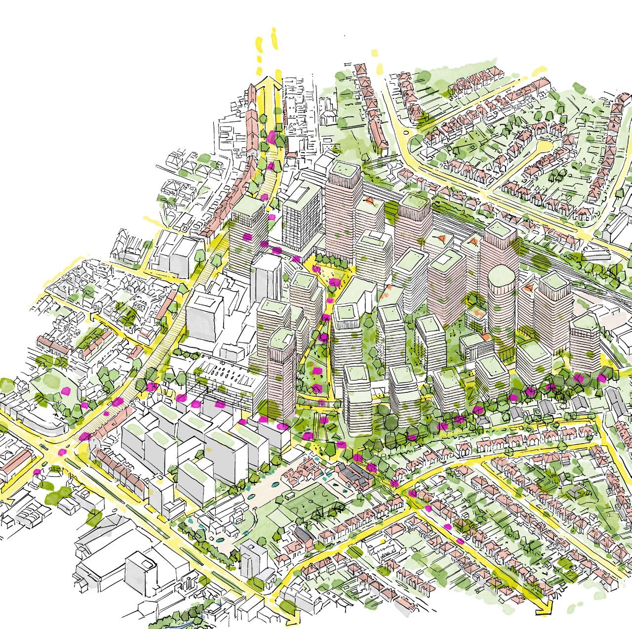
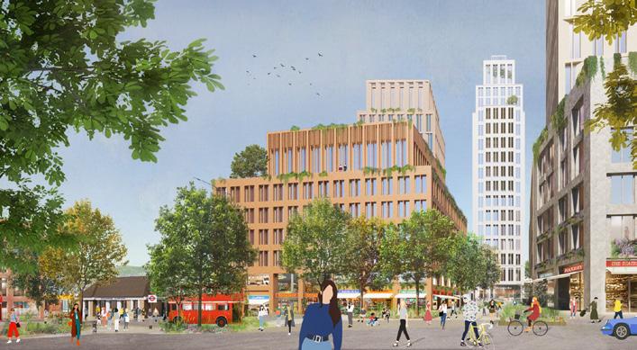
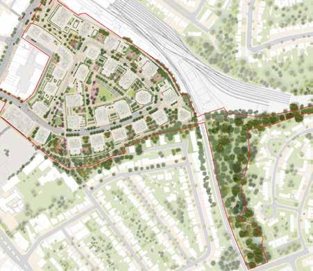
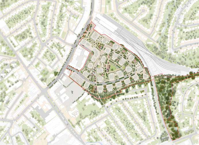
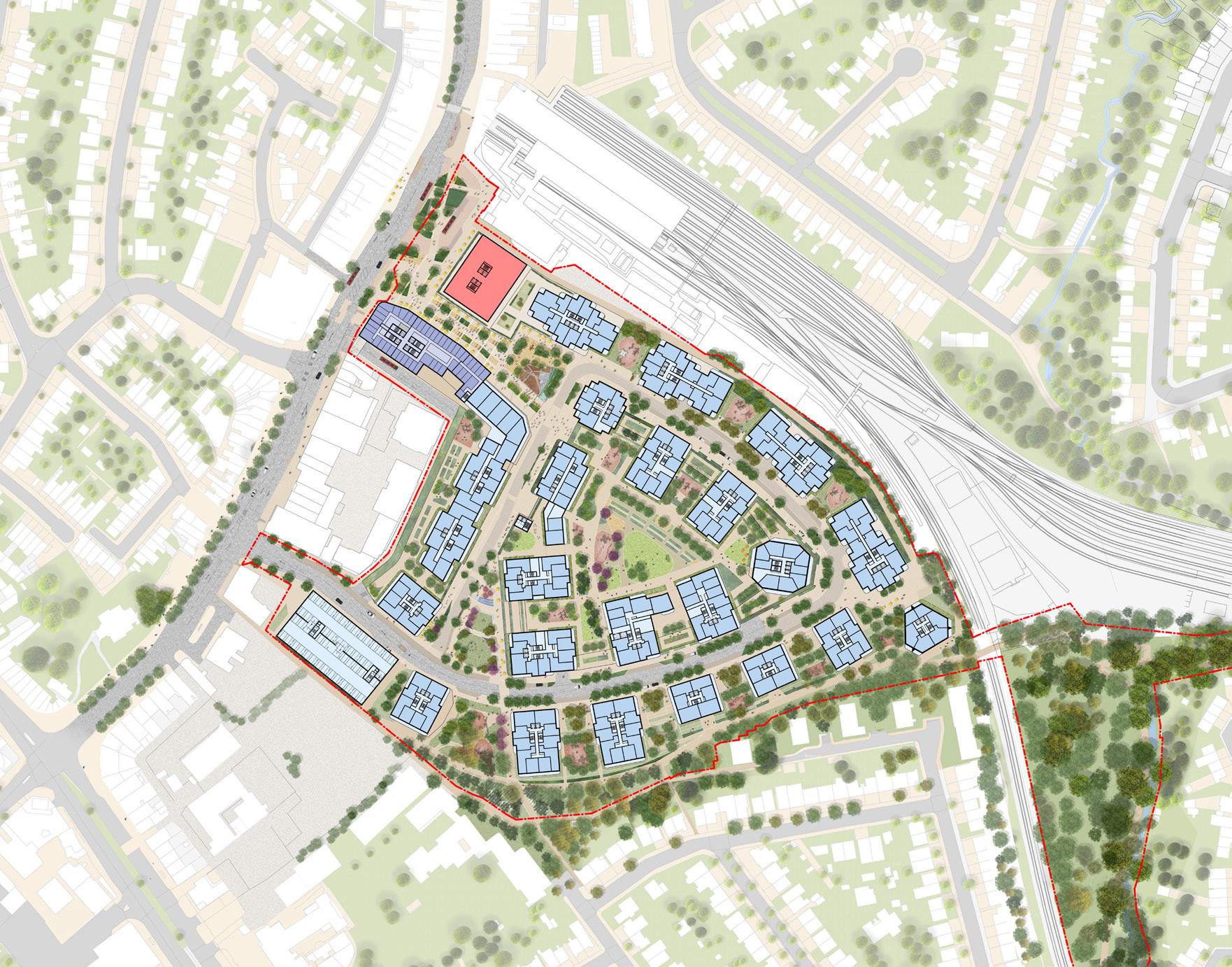
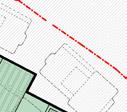
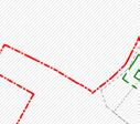
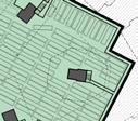
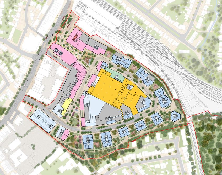
The Edgware Town Centre masterplan transforms the site into a permeable network of walkable streets which delivers thousands of new homes, accessible green space, public open space, new retail and cultural destinations, and an elegant and sustainable transport interchange.
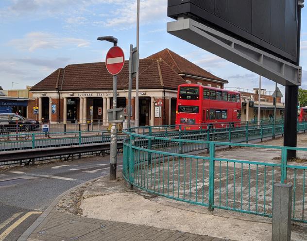
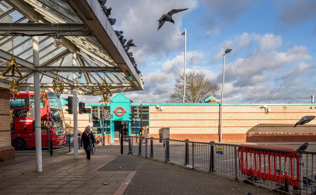
Create a World Class Transport Interchange
Create a safer and more integrated public transport user experience, reduce air pollution, and improve the appearance of Station Road. Futureproof delivery of the first fully electrified underground bus depot in the UK and facilitate a fully electrified TfL bus fleet.
Create a Walkable and Cyclable District
Improve permeability and connectivity from Edgware to other neighbouring destinations.
Repair the existing urban grain and create a high-quality pedestrian experience connecting destinations along desire lines within the site and beyond. Support local cycle routes and promote active travel with new cycle infrastructure and a cycle hub for commuters.
Cultivate a sense of local pride and deliver a new civic centre with a multi-purpose programmable public space, diverse retail offer and a new cultural destination at the heart of the scheme. Revitalise Edgware Town Centre with generous and high-quality new public realm and urban greening.


Celebrate Edgware as a local centre for culture and commerce by introducing new cultural and community destinations as anchor points at the heart of the new masterplan. Support a vibrant local economy through the introduction of diverse retail, commercial and workplace offers. Futureproof access and integration of the Forumside sites and restoration of the grade II listed Railway Hotel.
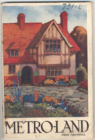
Restore Edgware's reputation as a green and healthy place to live through the creation of new parks and play space for the community. Create new public links to previously inaccessible green space and improve access to nature in the wider locality.
High-Quality and Diverse Homes for Edgware
Create new and multi-generational homes which support a diverse and inclusive community including first time homes, affordable homes, family homes, later living and student accommodation. Deliver homes which adhere to the highest standards of design and residential quality with access to daylight, fresh air and open space.


Deliver a fossil fuel-free development which adheres to the highest standards of sustainability and conforms to internationally recognised benchmarking schemes. Enable a world-class fully electrified transport interchange, encourage active modes of travel, provision of EV infrastructure and electric car club schemes, to improve air quality in the town centre.
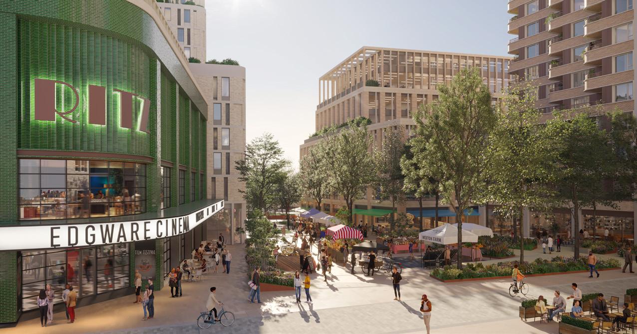
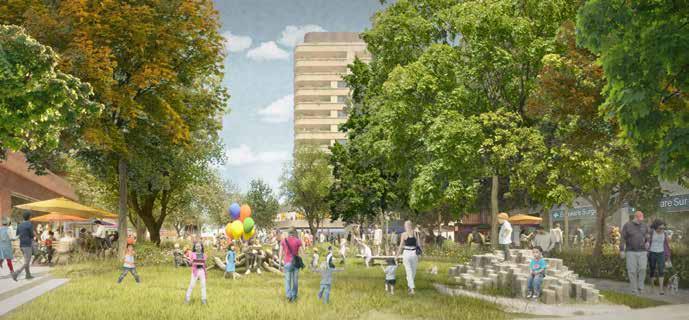
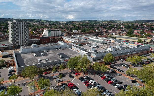
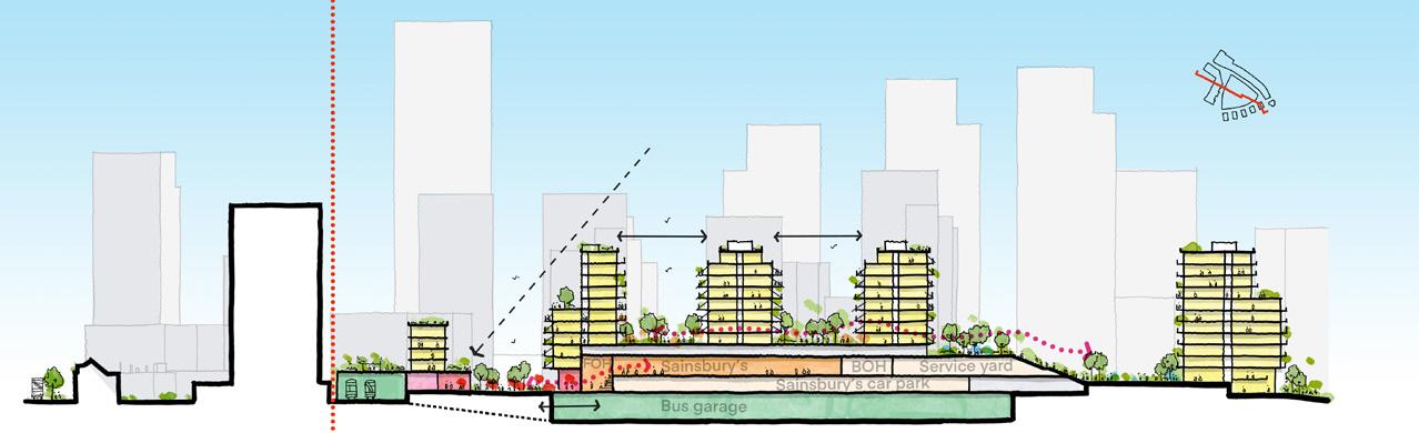
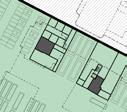
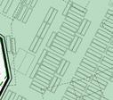
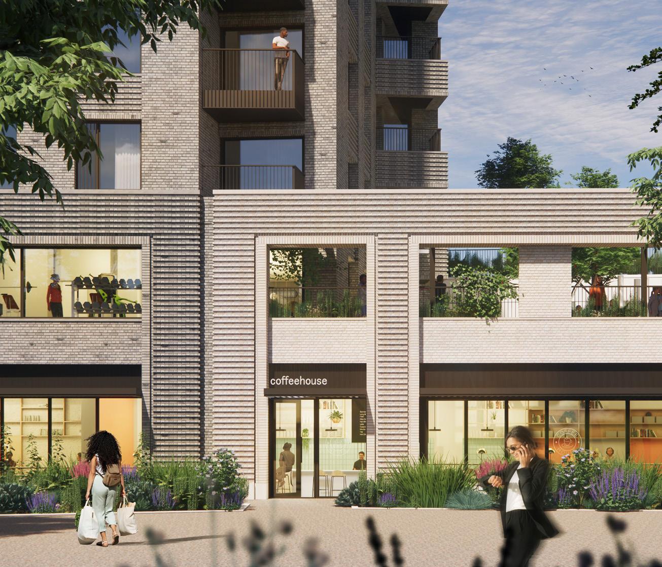
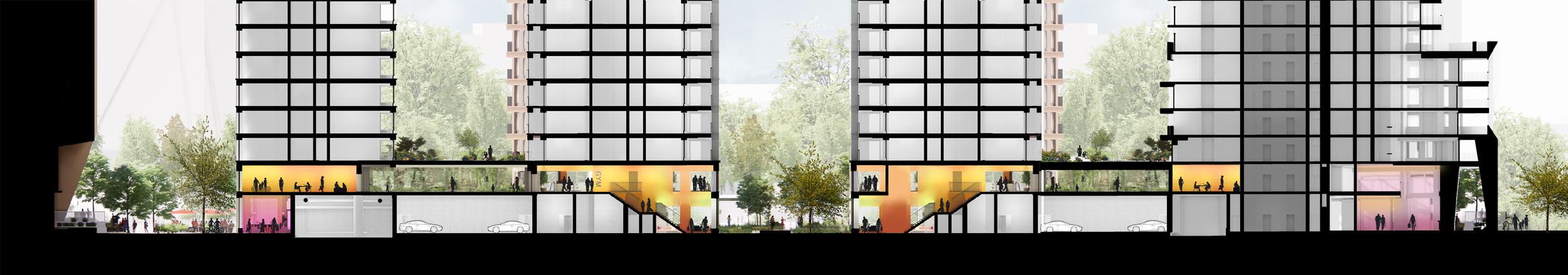
An illustrative scheme was developed to demonstrate the viability and achievable spatial quality of the proposed maximum parameters. Central to the proposal is the stacking of the reprovided bus depot and Sainsbury’s superstore to form a central podium, reclaiming a majority of the ground level for pedestrian use. The pedestrian experience is then framed by a series of public squares and parks that provide a transition from the busy transportation hub located adjacent to the existing high street, to a retail- and civic-focused town square, and finally, to a chain of public parks and playgrounds which lead to a new connection to the adjacent nature reserve.
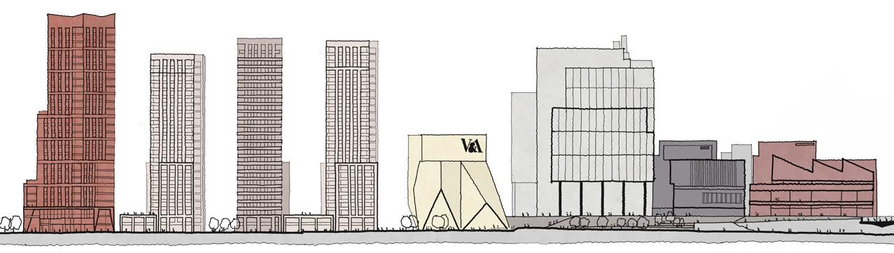
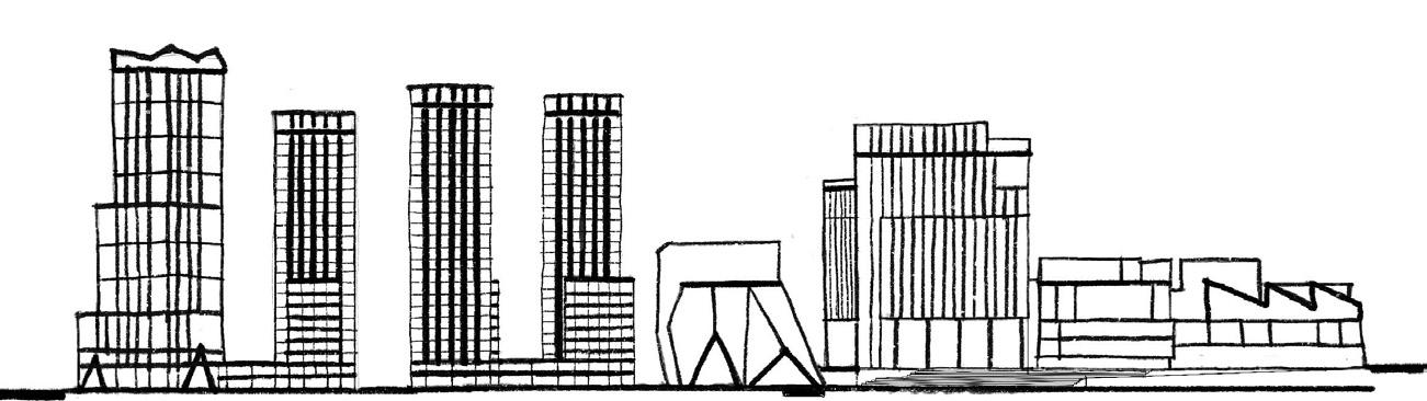
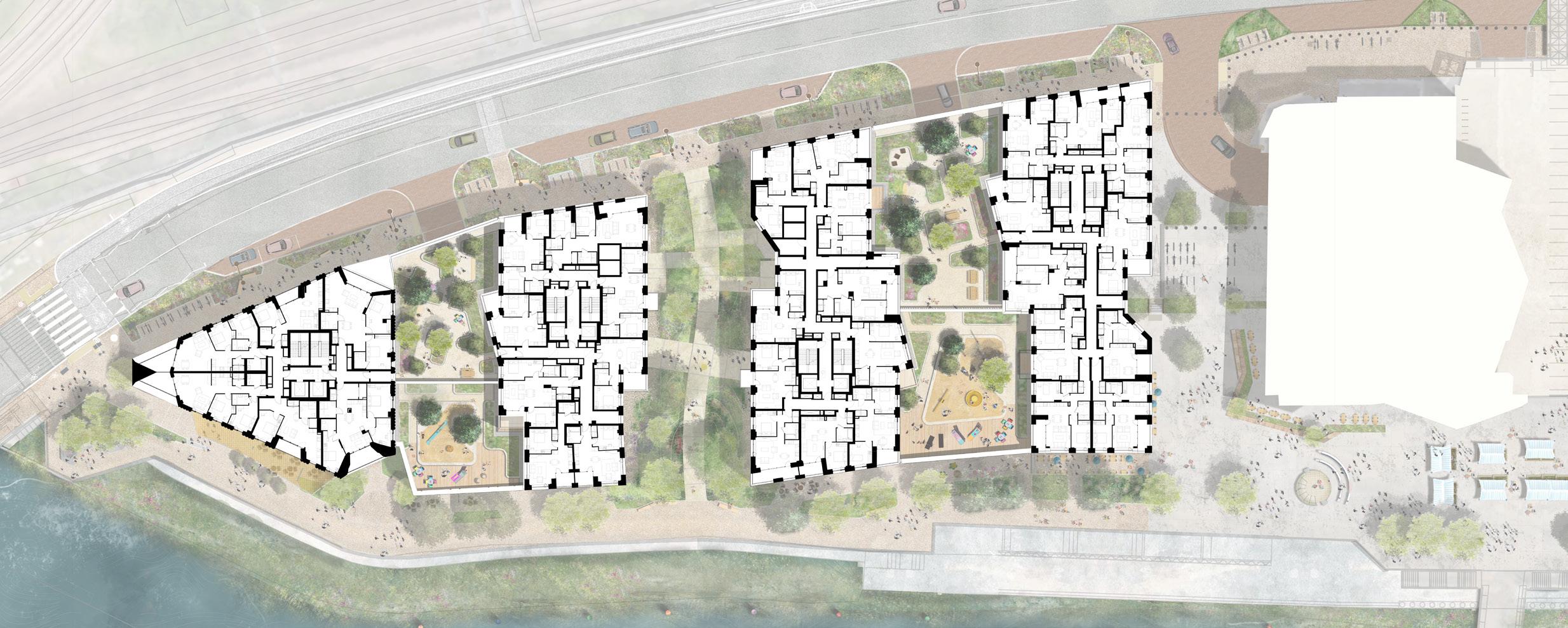
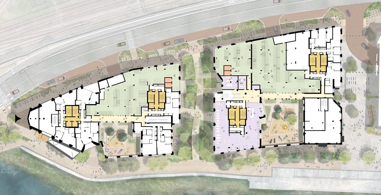
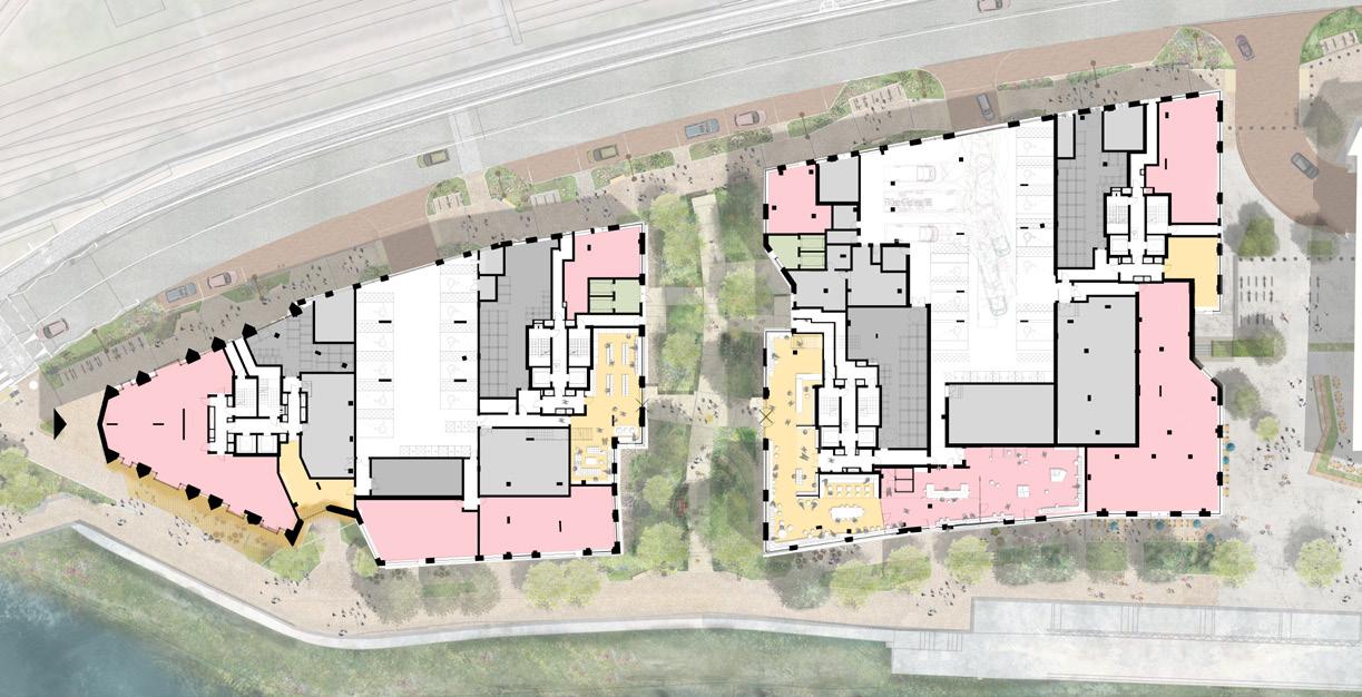
This project involved the delivery of RIBA Stage 3 design development and the preparation of the Reserved Matters Application for the residential quarter within the Stratford Waterfront masterplan.
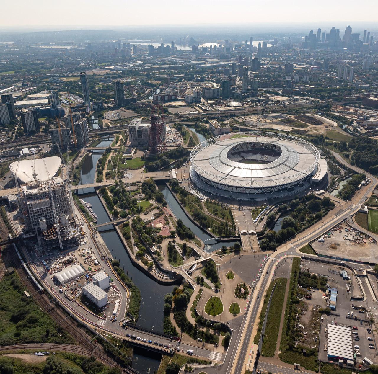
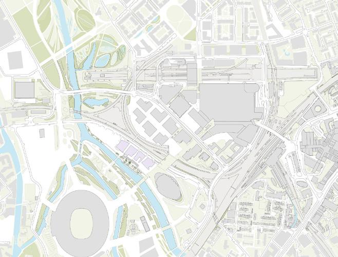
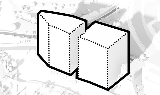


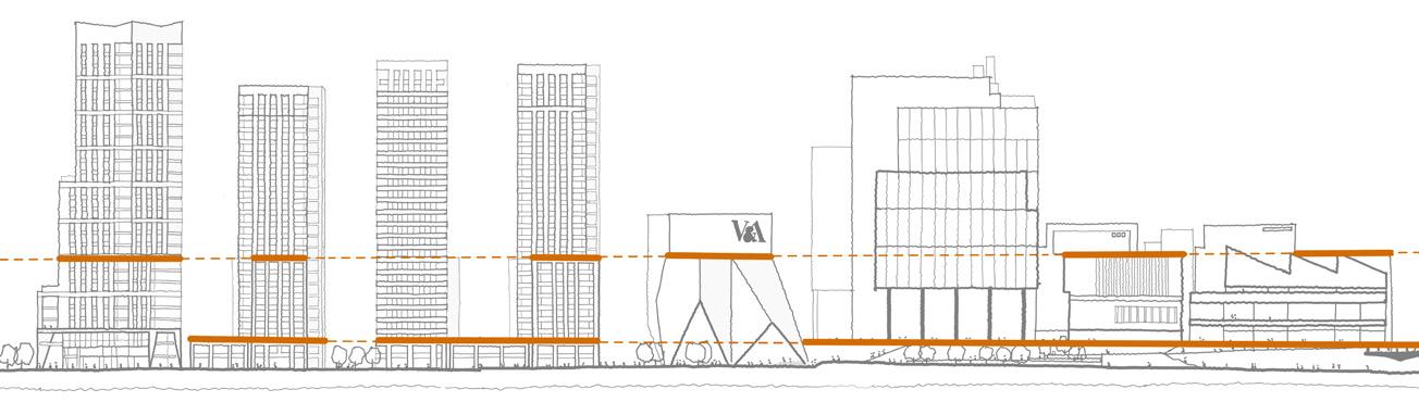
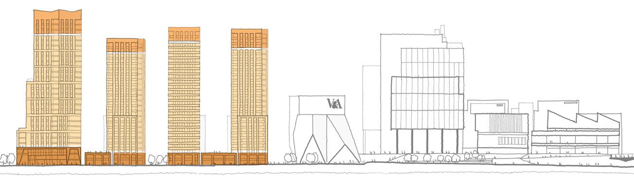
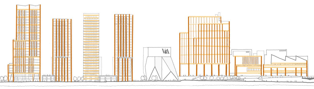
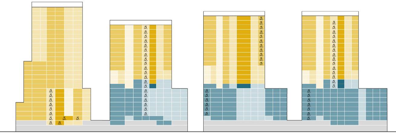
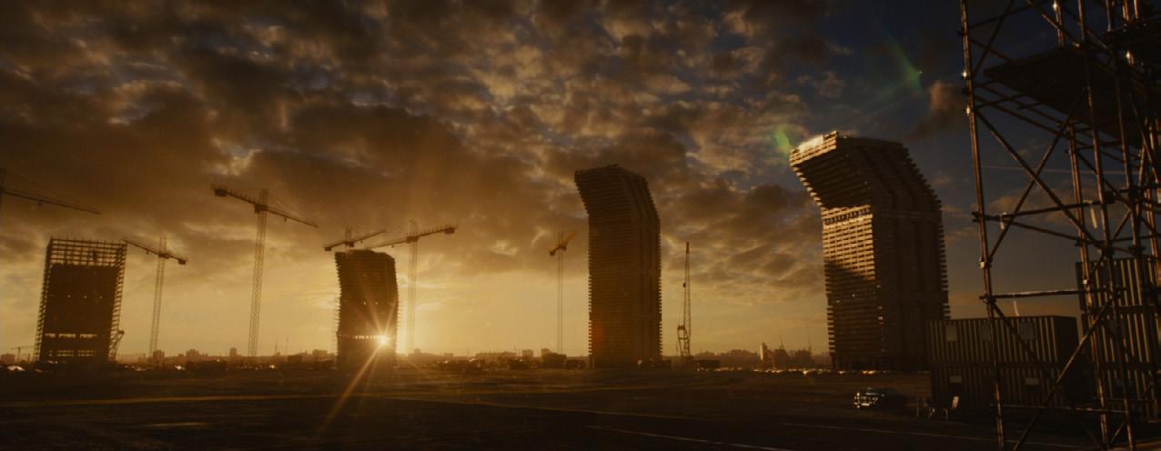
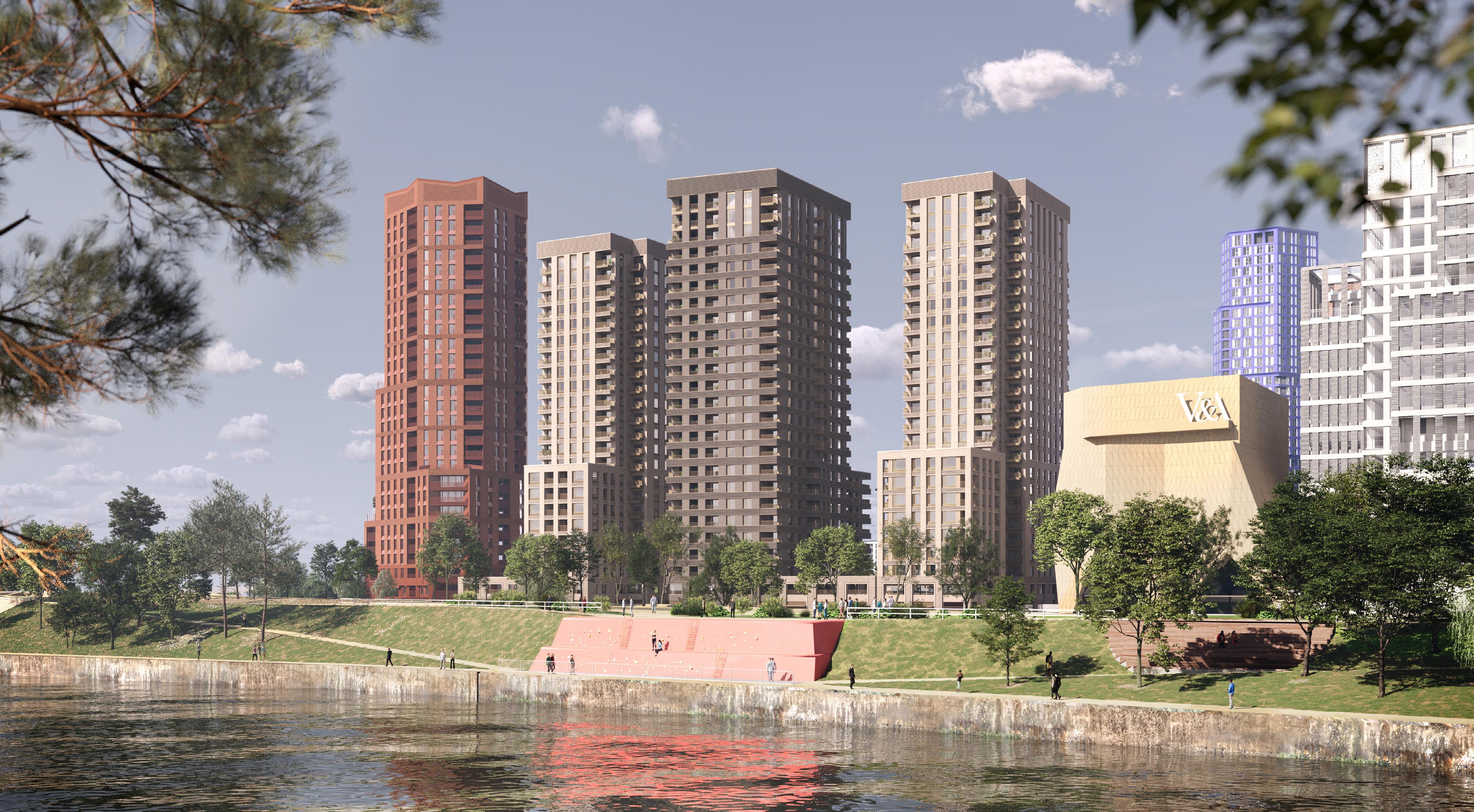
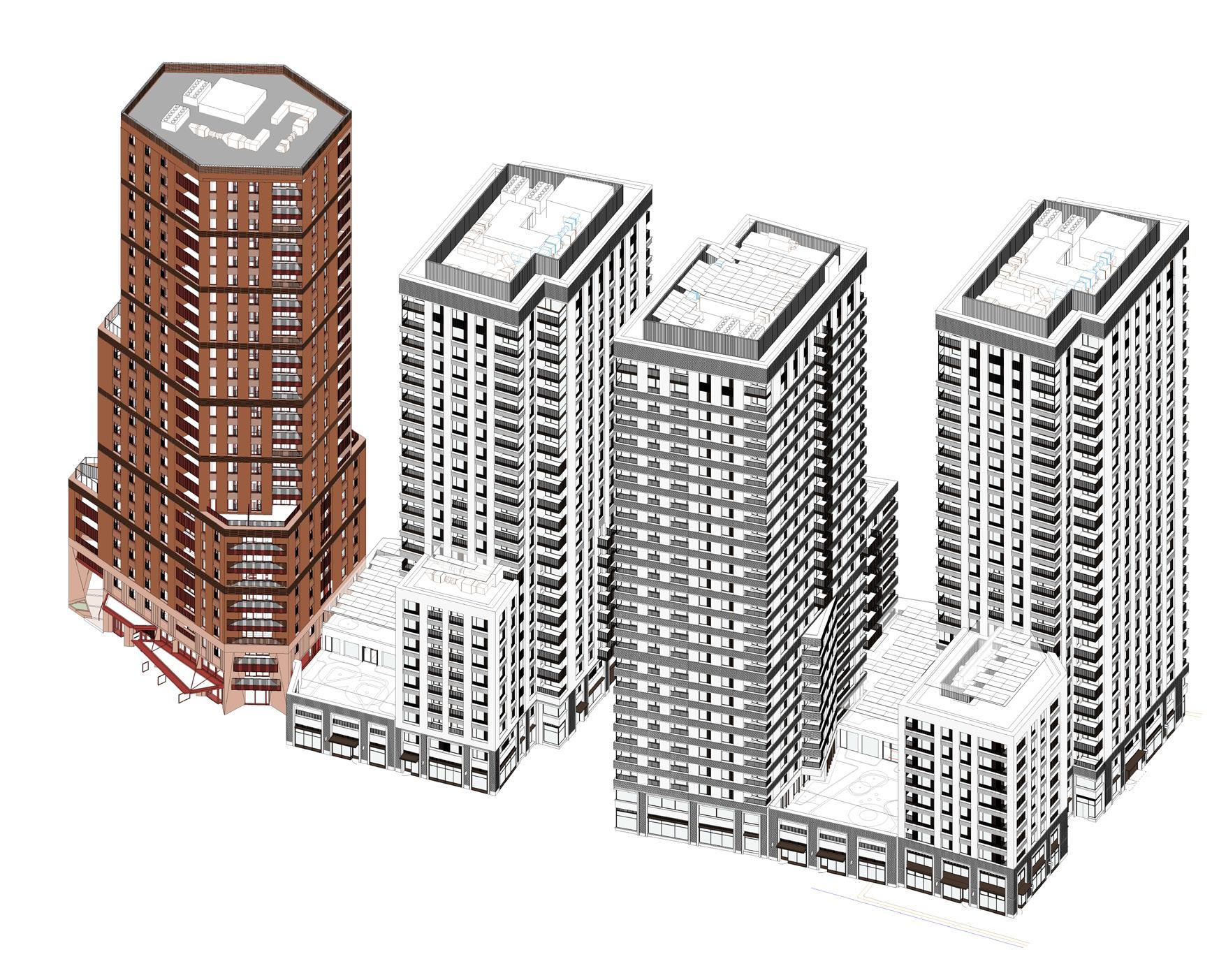
The residential quarter of the Stratford Waterfront masterplan, with outline consent to provide 700 homes and associated supporting commercial and ancillary uses, contains four buildings. The facade design development of the leading tower was executed in collaboration with O’Donnell+Tuomey. The detailed massing, with maximum parameters agreed under the outline consent, was derived from a series of moves to introduce
access, and create a dynamic townscape. Facade organisation principles were established to maintain the collective identity of the buildings within the masterplan as a cluster.
In
In developing the architectural
were
For
the best response to local context and the adjacent East Bank buildings.
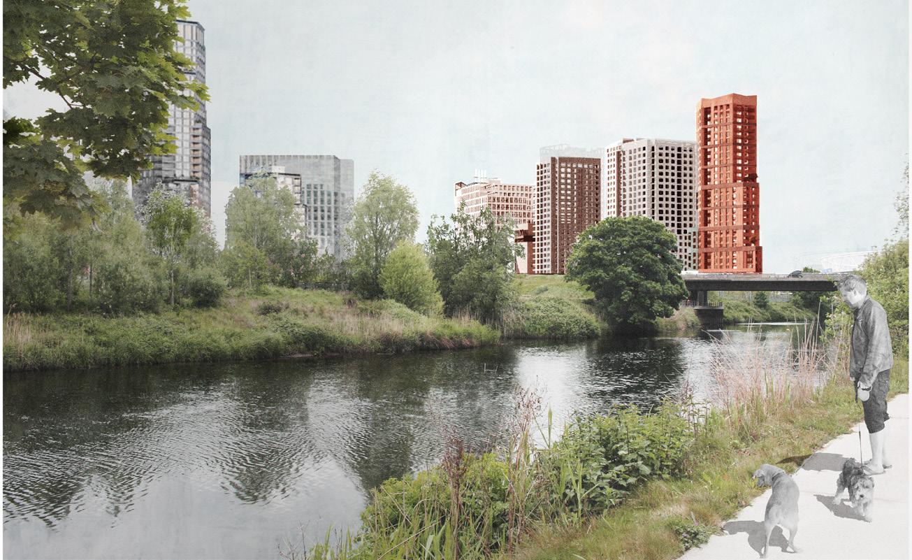
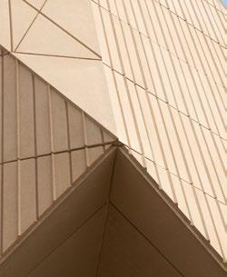
In developing the architectural vision, the material selection was driven by a commitment to sustainability and high quality design. In compliance with the Design Code, materials ‘Of the Earth’ were considered as the best response to local context and the adjacent East Bank buildings.
The materiality of the East Bank is composed of pre-cast, brick and metal. The emphasis on large format pre-cast conveys the formal quality complementary to the civic and educational function of the buildings in the cultural quarter. The appropriate selection of materials ensures the proposal will fit within its surrounding context, in line with Policy BN.5.
The materiality of the East Bank is composed of pre-cast, brick and metal. The emphasis on large format pre-cast conveys the formal quality complementary to the civic and educational function of the buildings in the cultural quarter. The appropriate selection of materials ensures the proposal will fit within its surrounding context, in line with Policy BN.5.
points, such as the Point, to tie the relationship with the East Bank.

Colour and tones were used to establish individual
To maintain the Prow’s identity as a
a deep burnt red has been
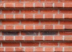
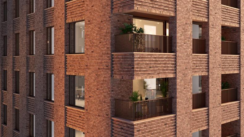
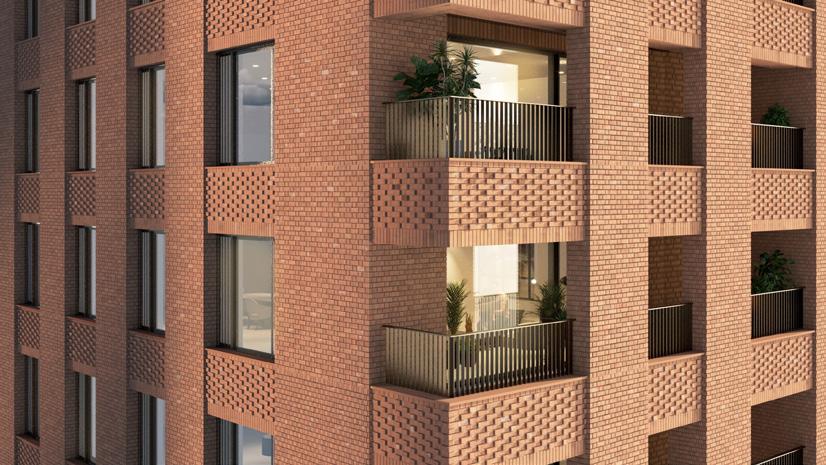
For the residential component, brick has been selected as the primary material to introduce qualities of human scale, since it reflects the use in many residential buildings. Variation in brick details, such as bond, pattern and tone is used to create variations and individual identity amongst the buildings. Pre-cast concrete is used at key wayfinding points, such as the Point, to tie the relationship with the East Bank.
For the residential component, brick has been selected as the primary material to introduce qualities of human scale, since it reflects the use in many residential buildings. Variation in brick details, such as bond, pattern and tone is used to create variations and individual identity amongst the buildings. Pre-cast concrete is used at key wayfinding points, such as the Point, to tie the relationship with the East Bank.
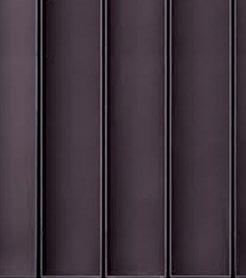

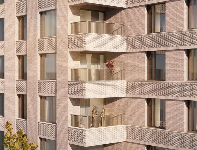
Colour and tones were used to establish individual identity between the residential buildings. They were given a warmer tone compared to the East Bank to set them apart from the civic and institution buildings.

The materials form a complementary palette to establish a coherent Waterfront composition and are deliberately chosen to enhance each other, ensuring a cohesive, visually appealing aesthetic that avoids coalescence. At a more detailed level, the colour of materials are used to establish individual identities for each building.
Colour and tones were used to establish individual identity between the residential buildings. They were given a warmer tone compared to the East Bank to set them apart from the civic and institution buildings.
To maintain the Prow’s identity as a landmark, a deep burnt red has been chosen.
To maintain the Prow’s identity as a landmark, a deep burnt red has been chosen.
The materials form a complementary palette to establish a coherent Waterfront composition and are deliberately chosen to enhance each other, ensuring a cohesive, visually appealing aesthetic that avoids coalescence. At a more detailed level, the colour of materials are used to establish individual identities
The materials form a complementary palette to establish a coherent Waterfront composition and are deliberately chosen to enhance each other, ensuring a cohesive, visually appealing aesthetic that avoids coalescence. At a more detailed level, the colour of materials are used to establish individual identities for
The
The
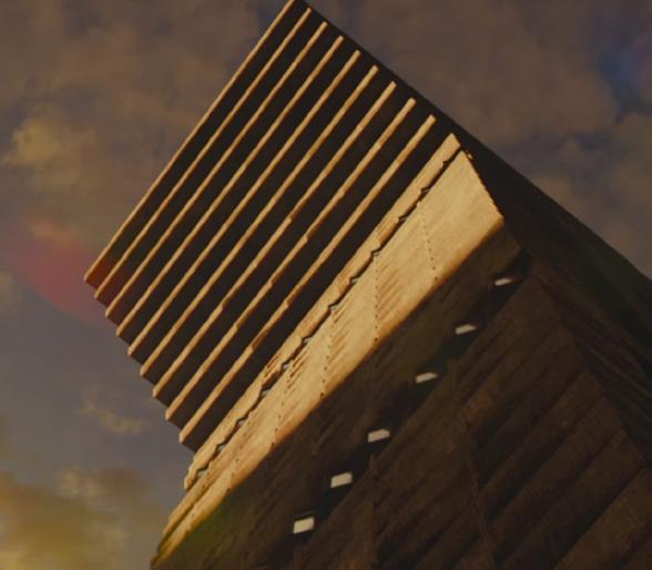
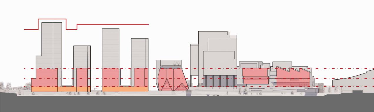
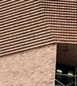
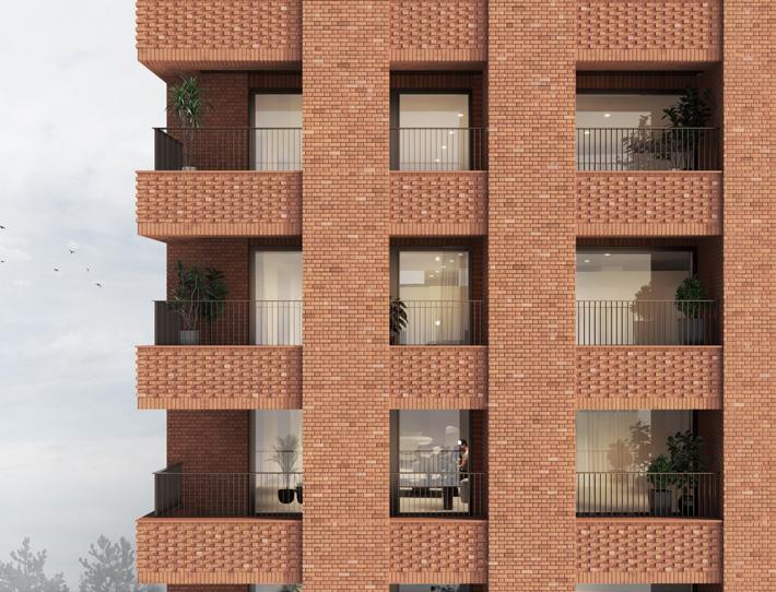
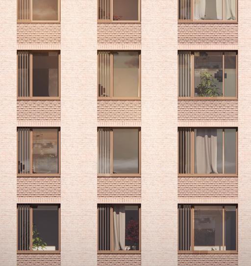
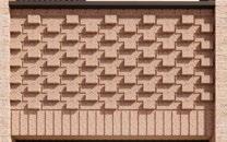
Rhythm and texture were introduced to the facade design through the use of differing brick bonds. These included Roman brick, Flemish bond, brick on edge and stacked brick. By applying different articulations to the buildings, individuality was established across the buildings.
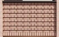
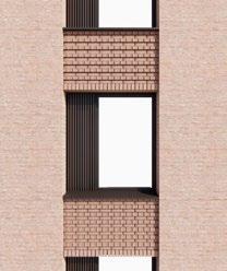
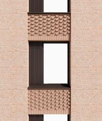
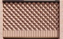
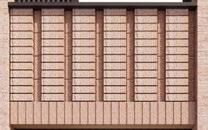
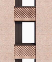
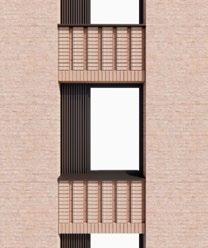
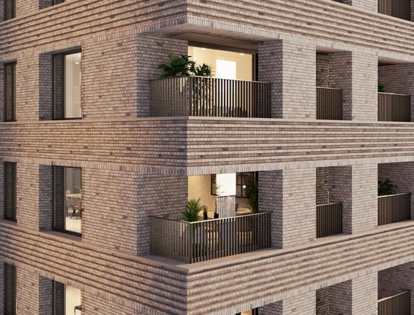
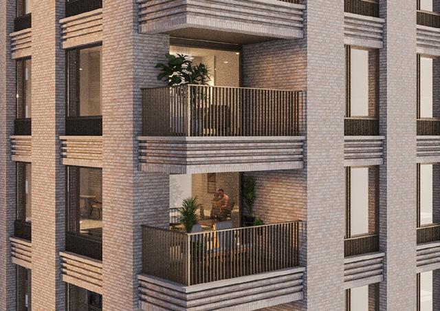
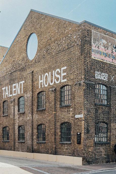
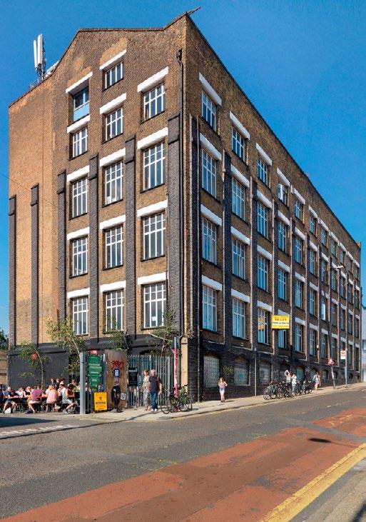
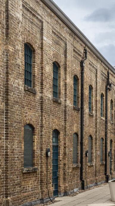
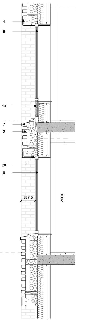
The facade design takes inspiration from how local industrial brick buildings create a sense of rhythm and vertical or horizontal emphasis through the repetition of piers or lintels. A rhythmic grid with varying vertical and horizontal emphasis was developed for the facade. The grid effect was achieved by recessing the vertical piers from the horizontal bands, or vice versa. The effect was further enhanced by the simple use of brick bonding with recessed detail. The developing brick details were tested at key junctions of the building to review how they would come together.
Glazed brick detail comes to edge
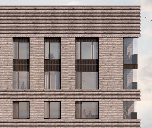
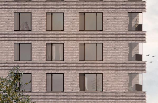
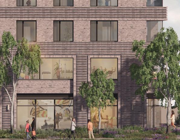
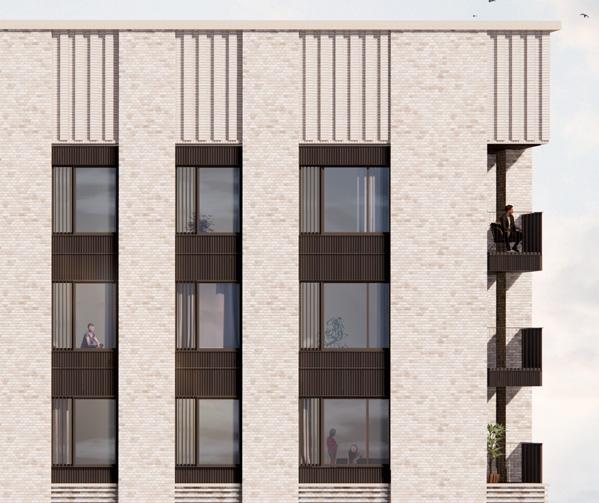
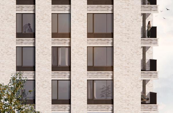
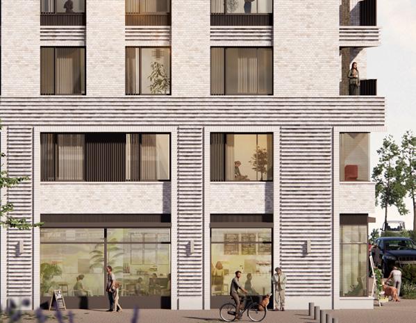
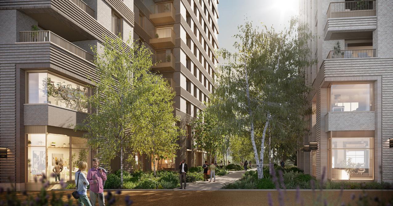
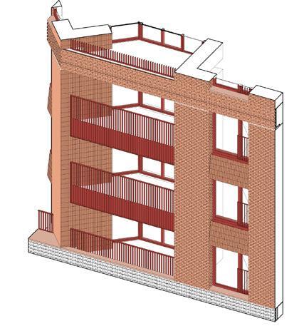
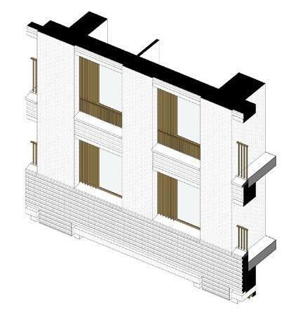
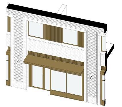
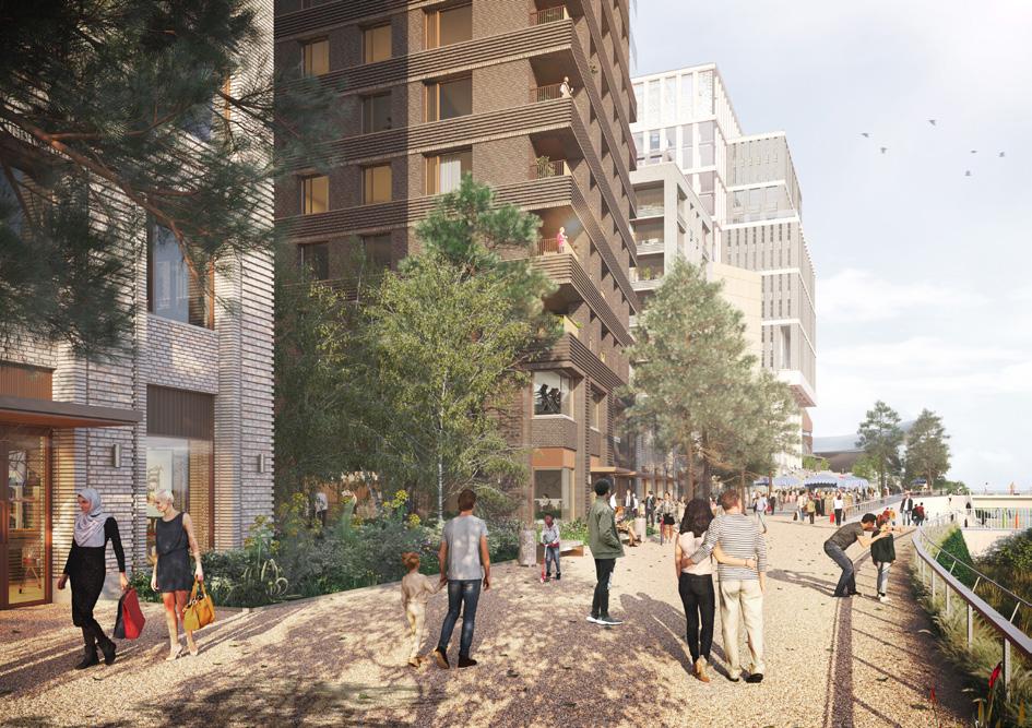
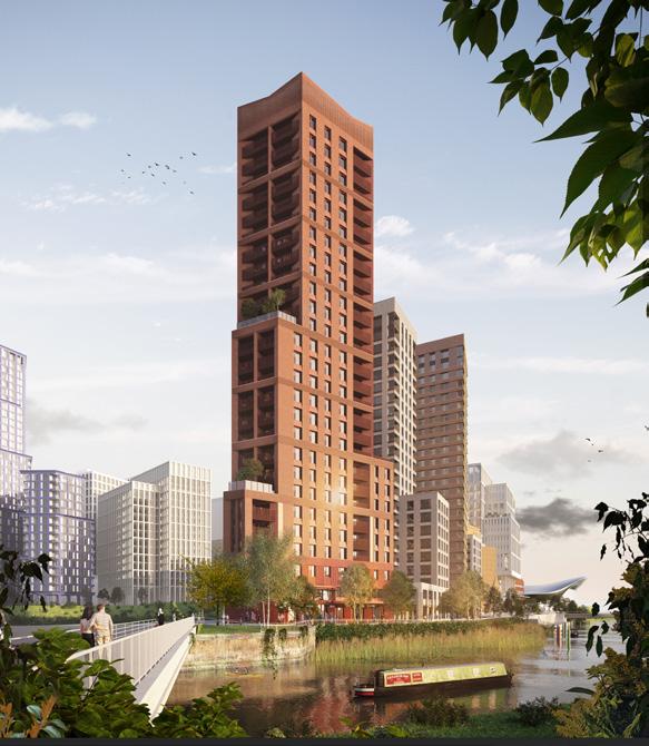

The rhythmic grid provides a unifying experience of the buildings as a whole when viewed from afar, while the brick textures offer richness when experienced up close. The brick patterns were intensified at the lower level of the buildings to enhance the dynamic experience within the public realm.
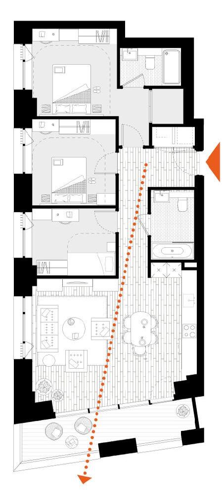
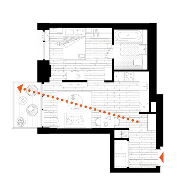

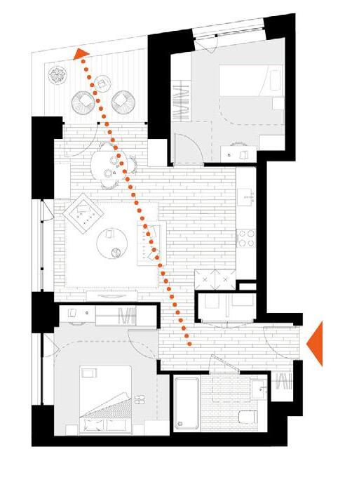
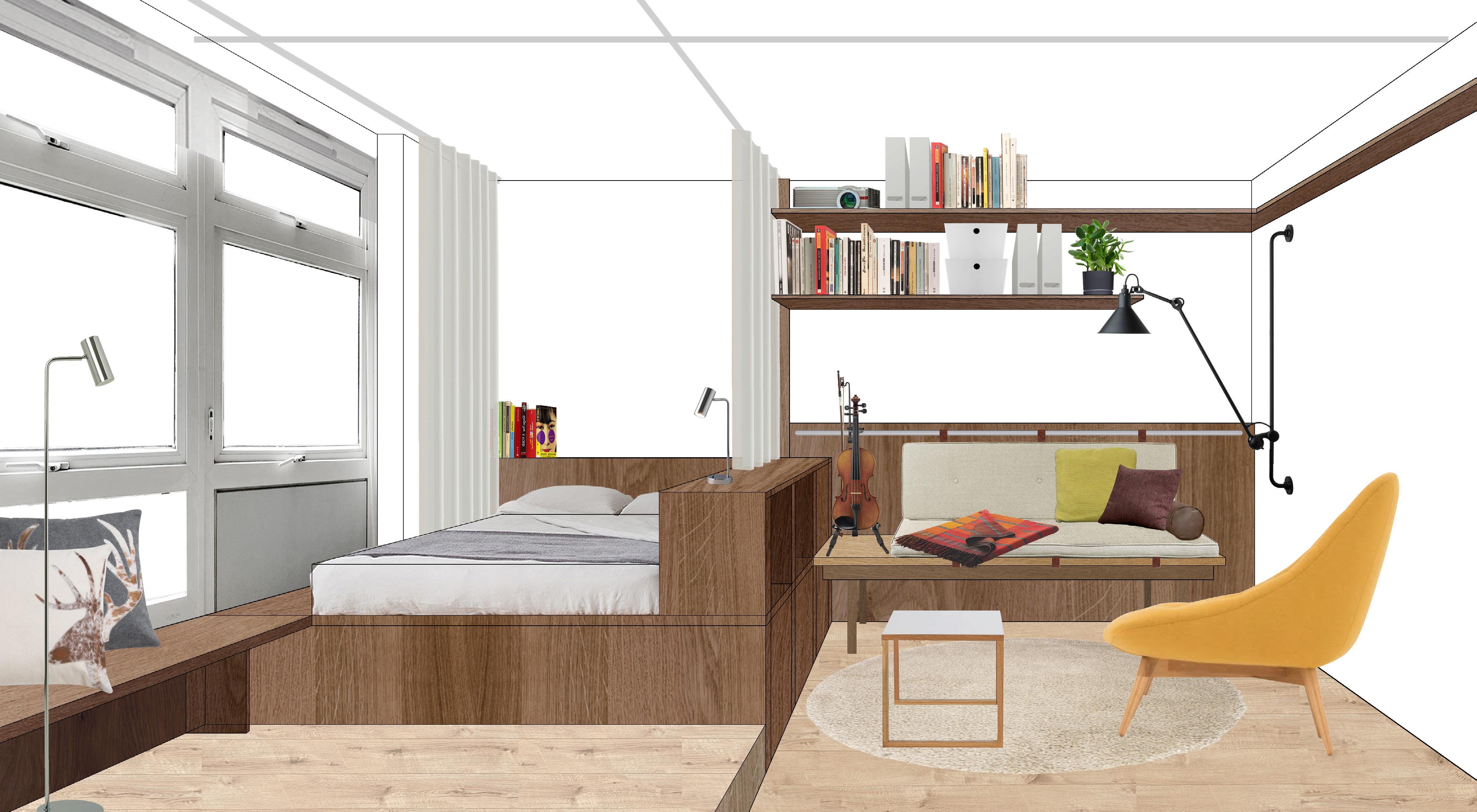
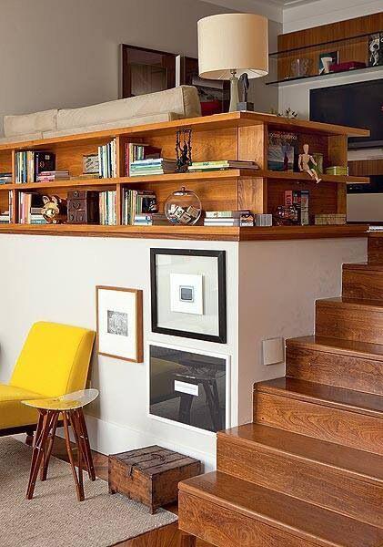
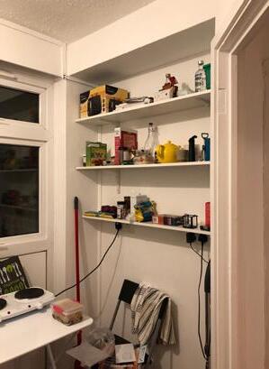
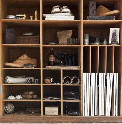
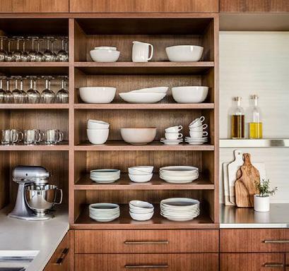
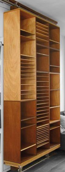
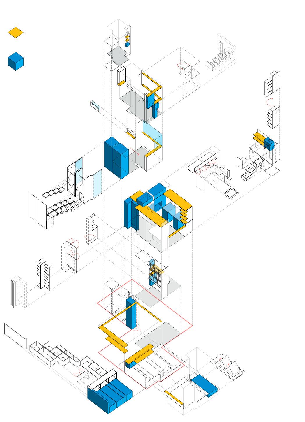
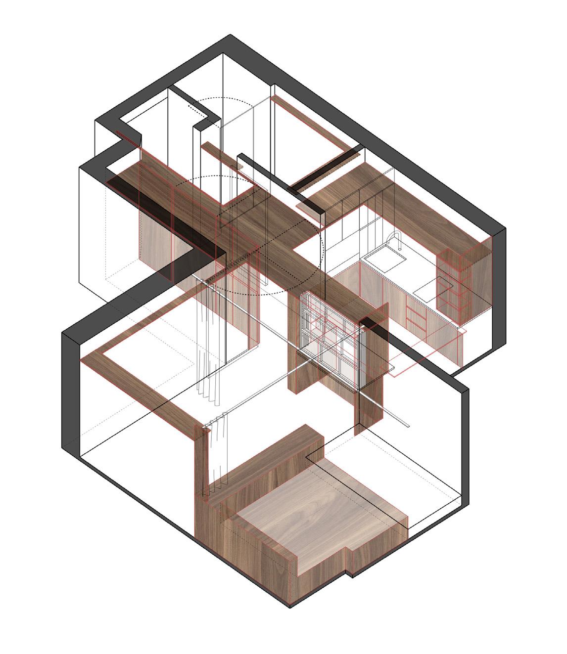
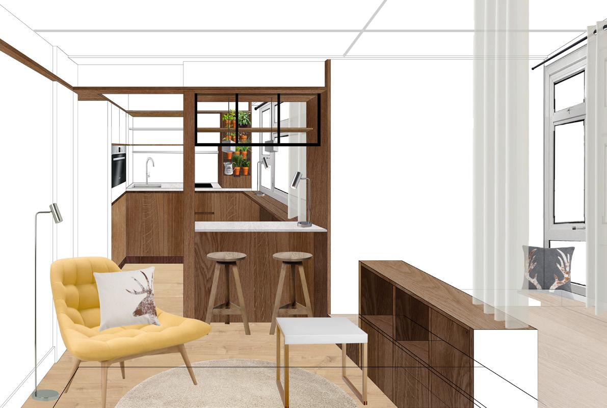
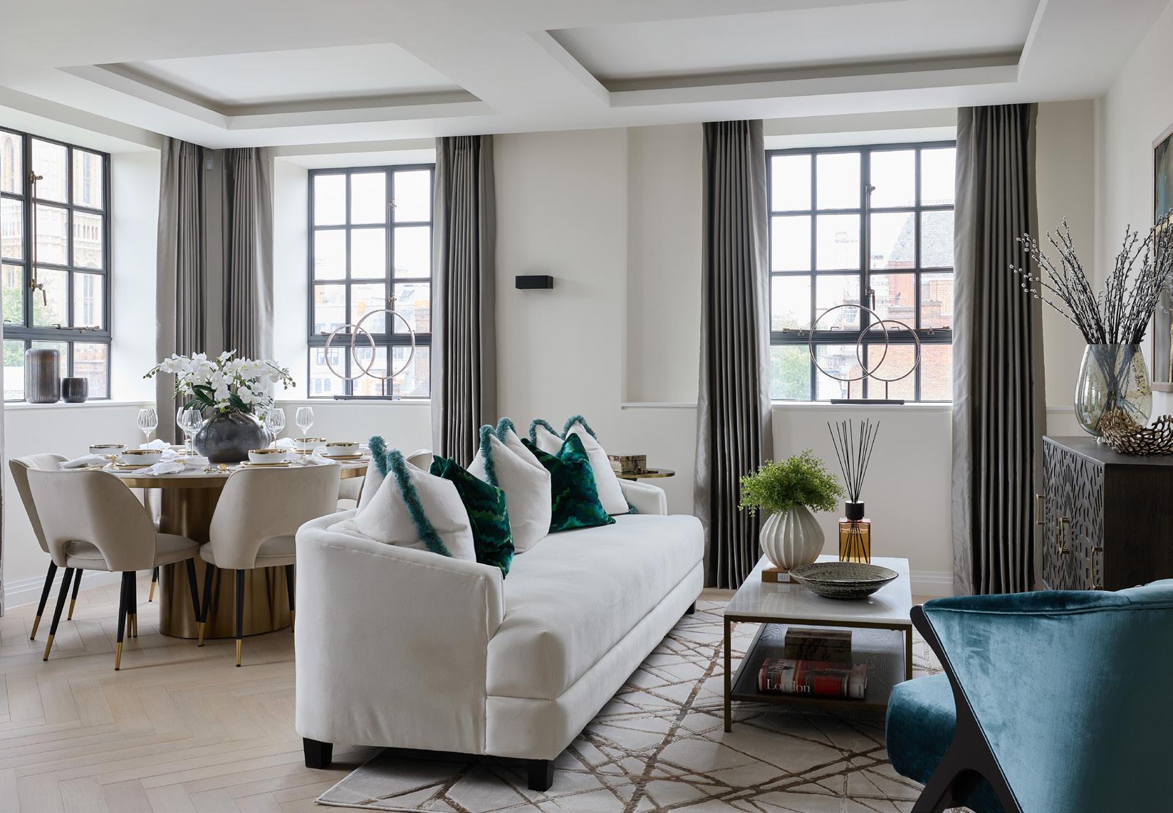
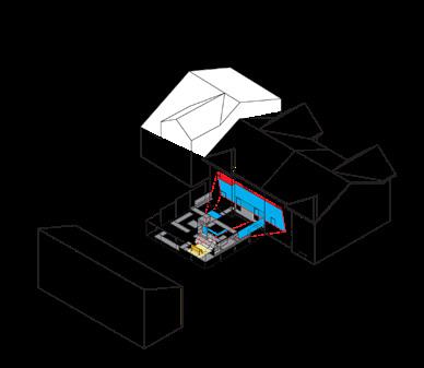
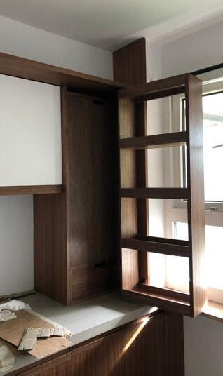
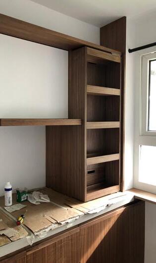
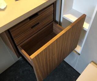
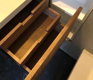
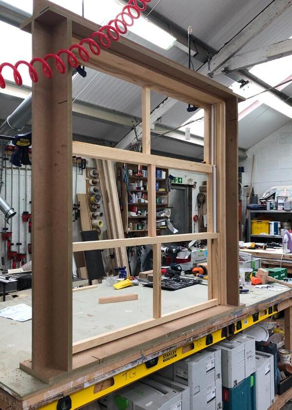
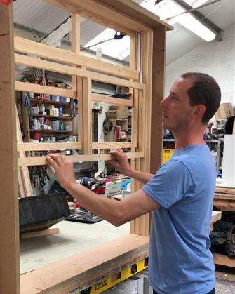
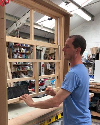
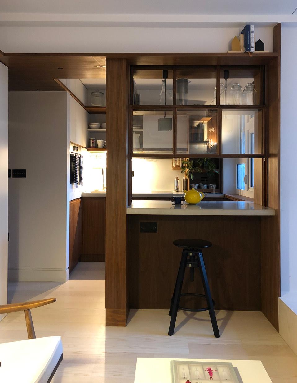
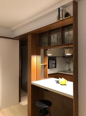
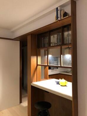
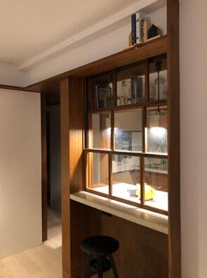
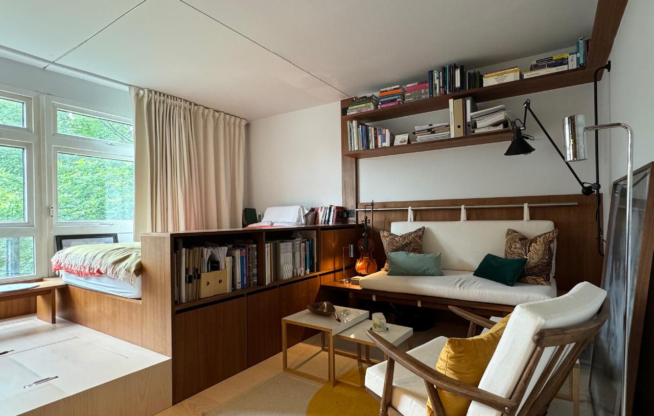
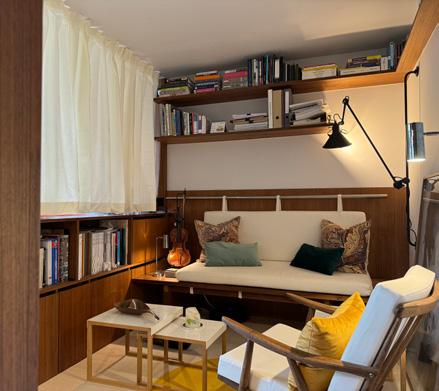
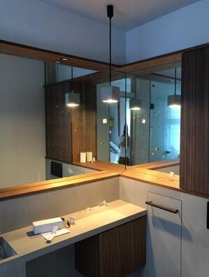
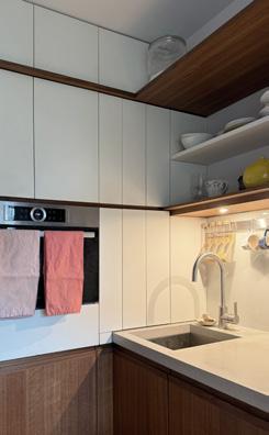
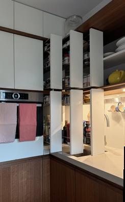
The underlying design explores the idea of our home as a place to accumulate and display the objects we have collected throughout our lives. The final design features a system of concealed and open shelving storage components, forming a joinery spine that unifies the flat into a giant Japanese puzzle box. The storage elements replace conventional walls to frame and define the different zones within the confines of this very small apartment.
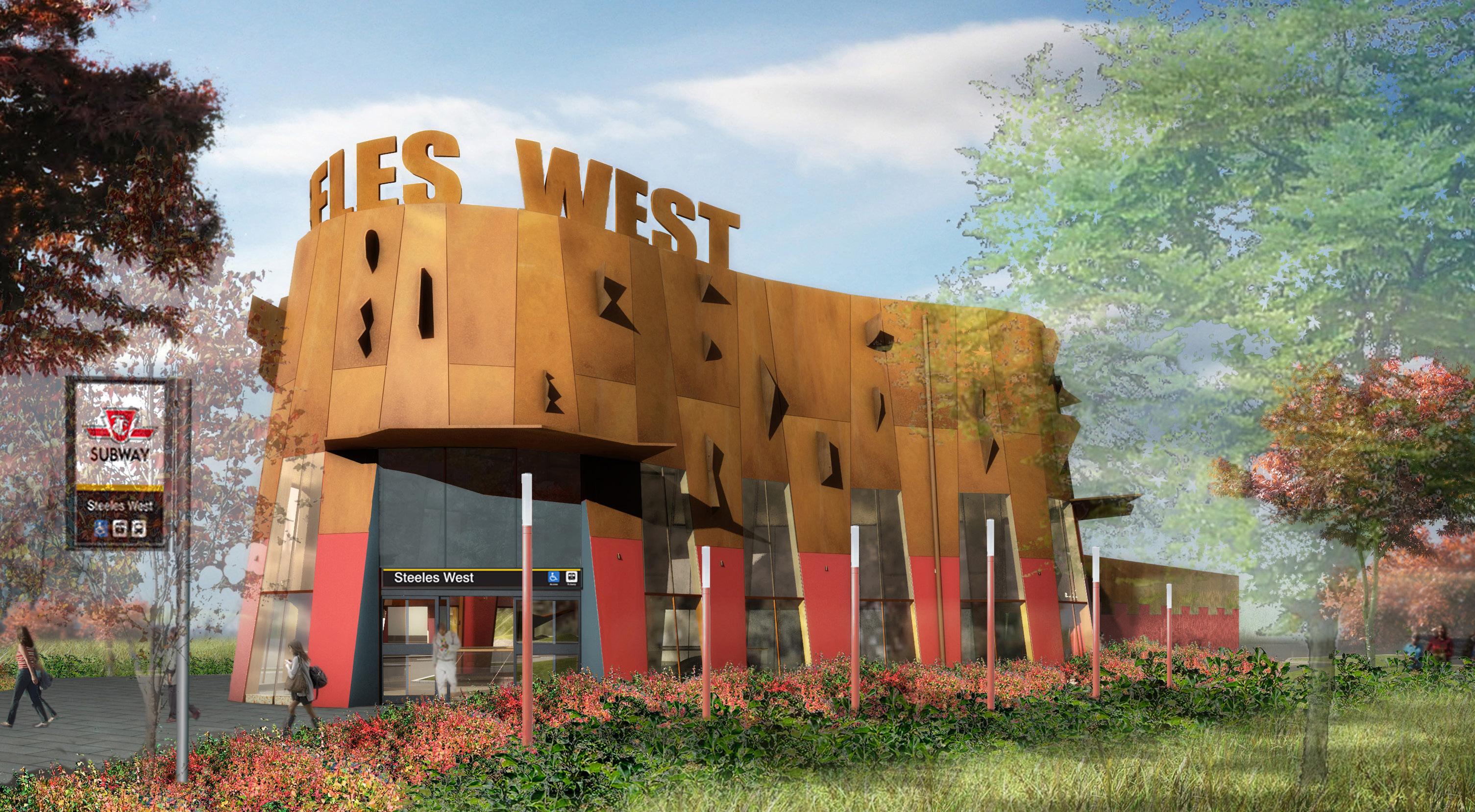
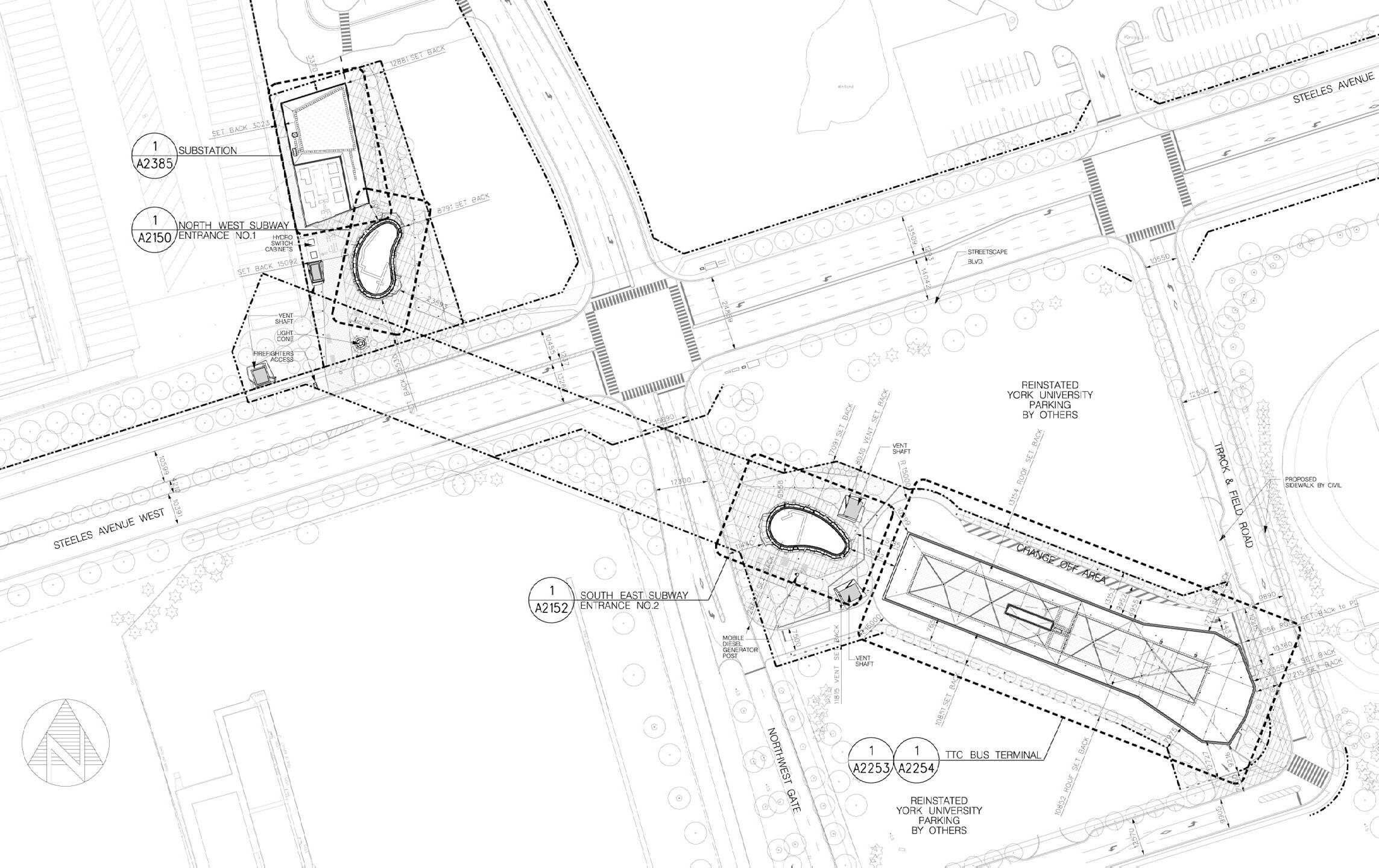
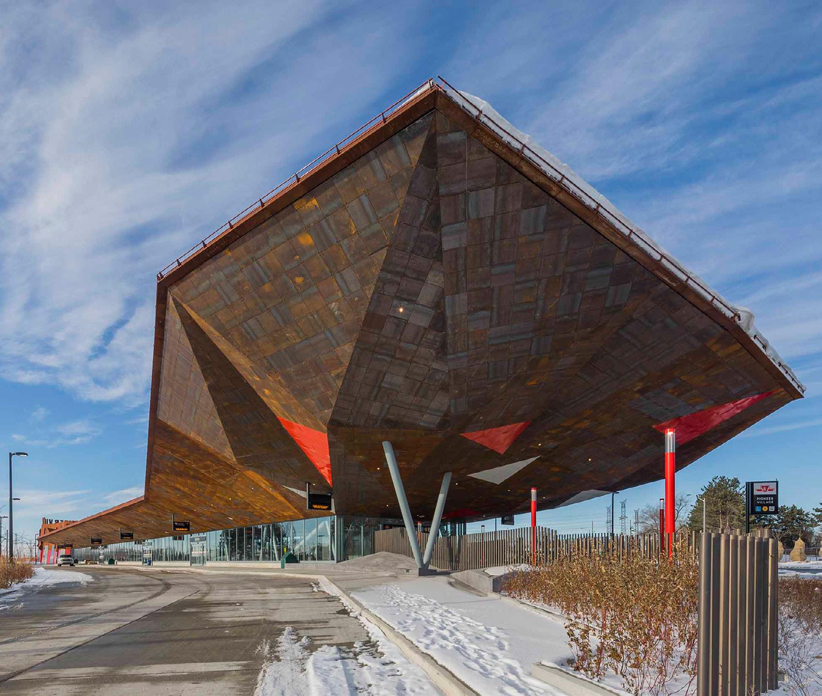
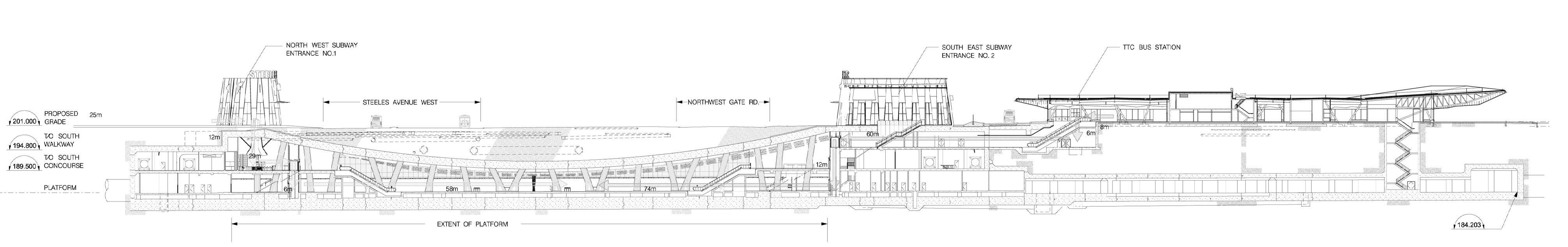
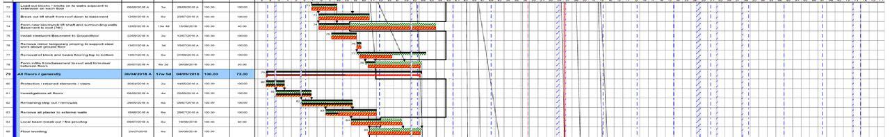
The project is a collaboration with Will Alsop as the designer. The program includes two underground station entrance buildings, a main bus terminal, a main underground platform, back-of-house operations areas, a drop-off area, parking, and associated service infrastructure, including a power substation and vent shafts.
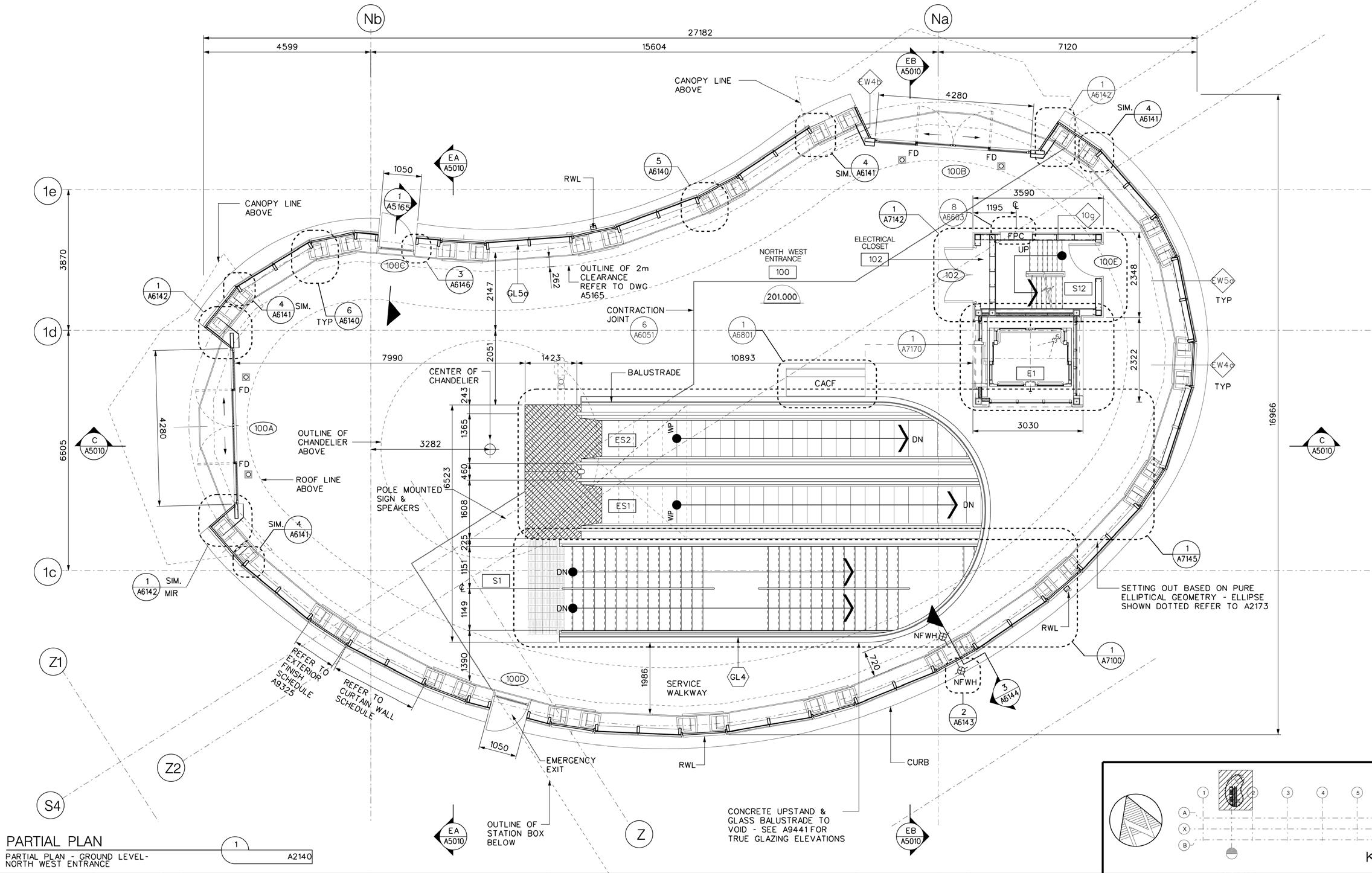
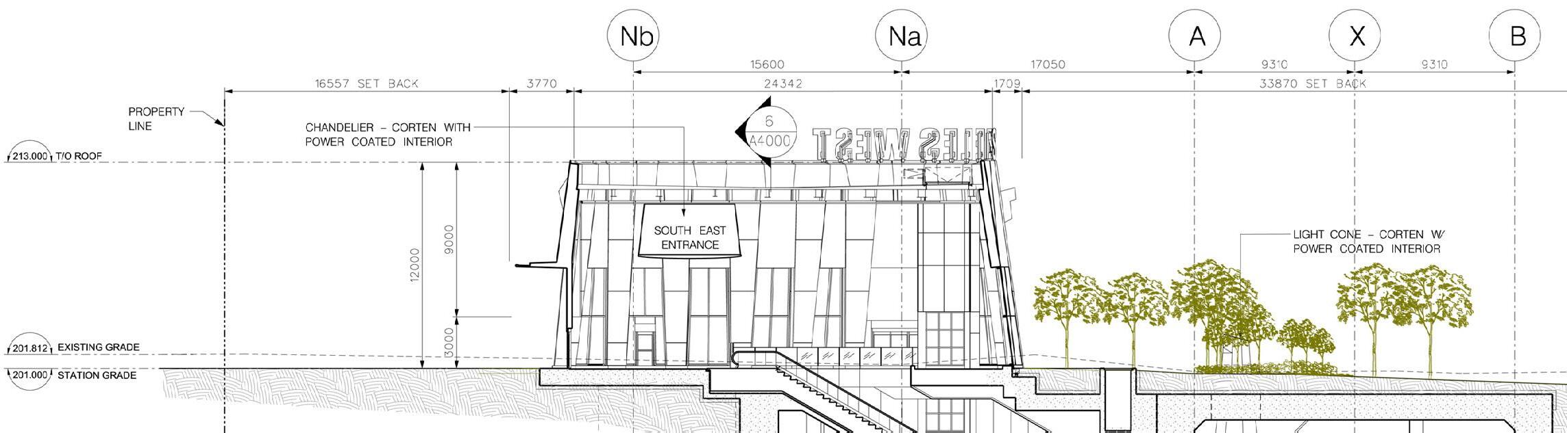
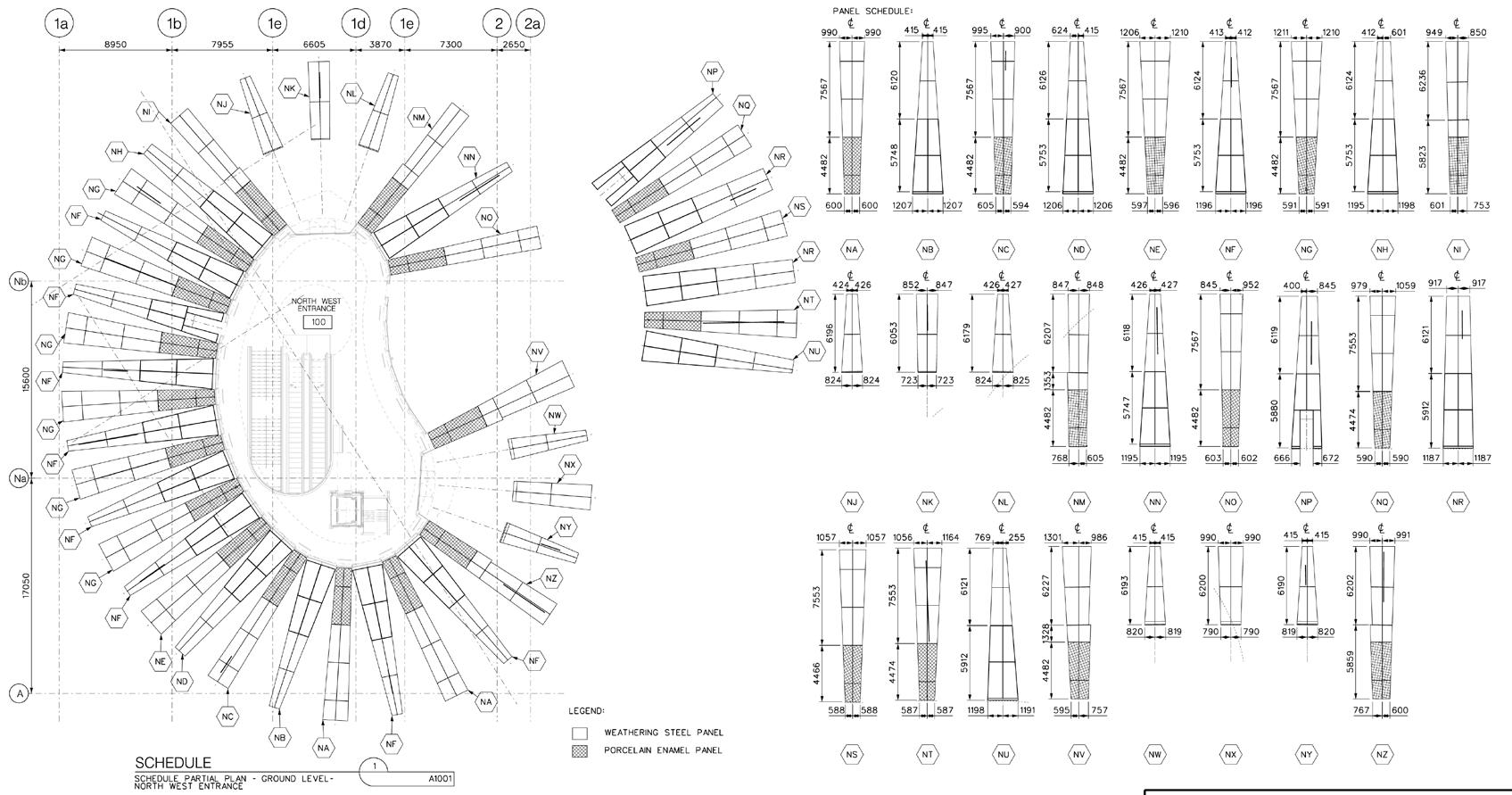
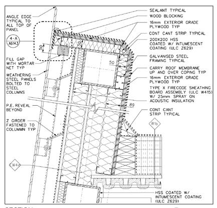
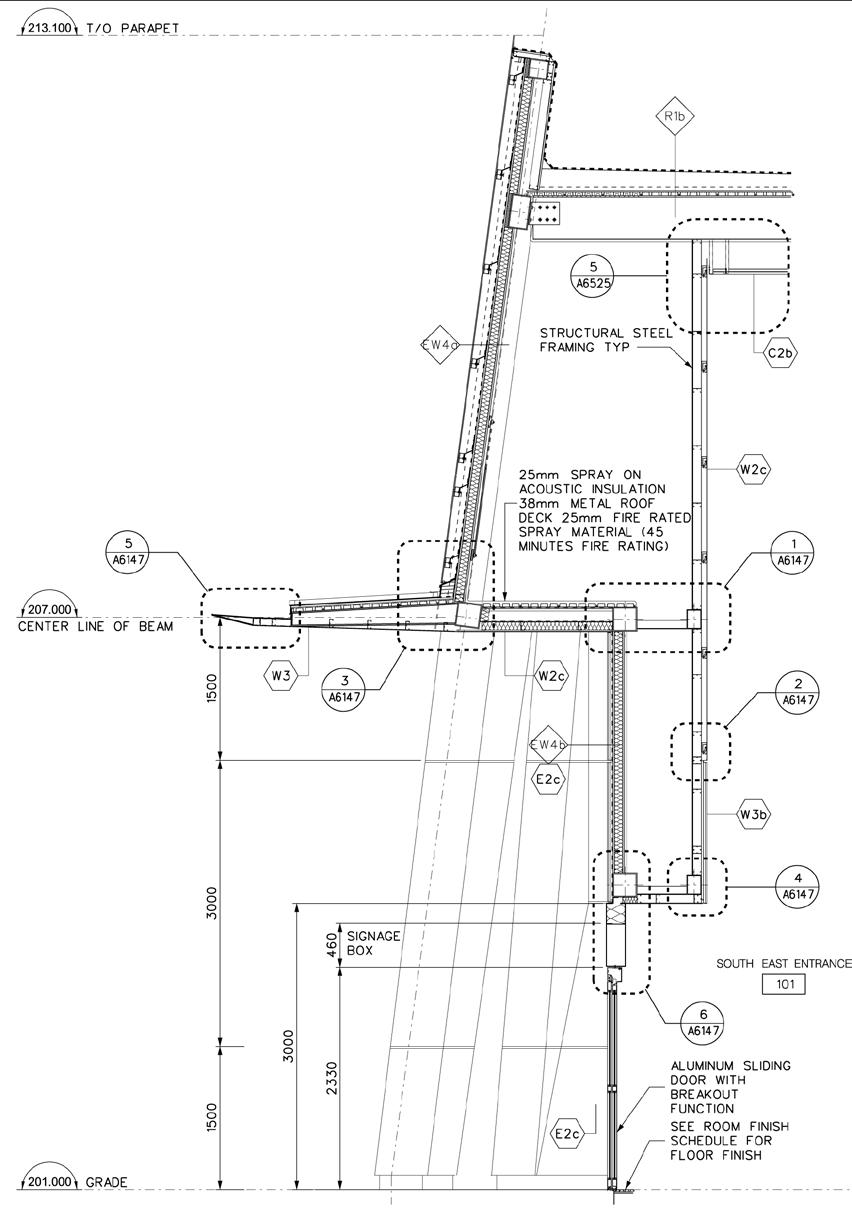
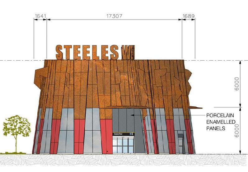
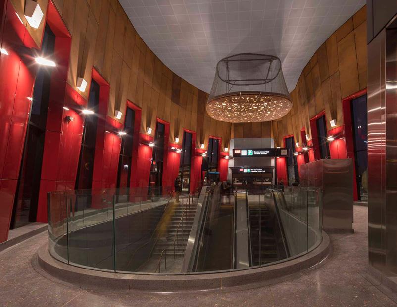
My key responsibility was to carry out detail design, technical coordination, and information preparation for the two entrance buildings, including coordinating the vertical circulation to the underground platform and planning-related submissions to the city. Apart from developing the necessary details to deliver the original design intent, in-depth considerations of in-use maintenance, durability, and potential health and safety concerns were the focus of the design development process due to the public nature of the buildings and the anticipated heavy usage.
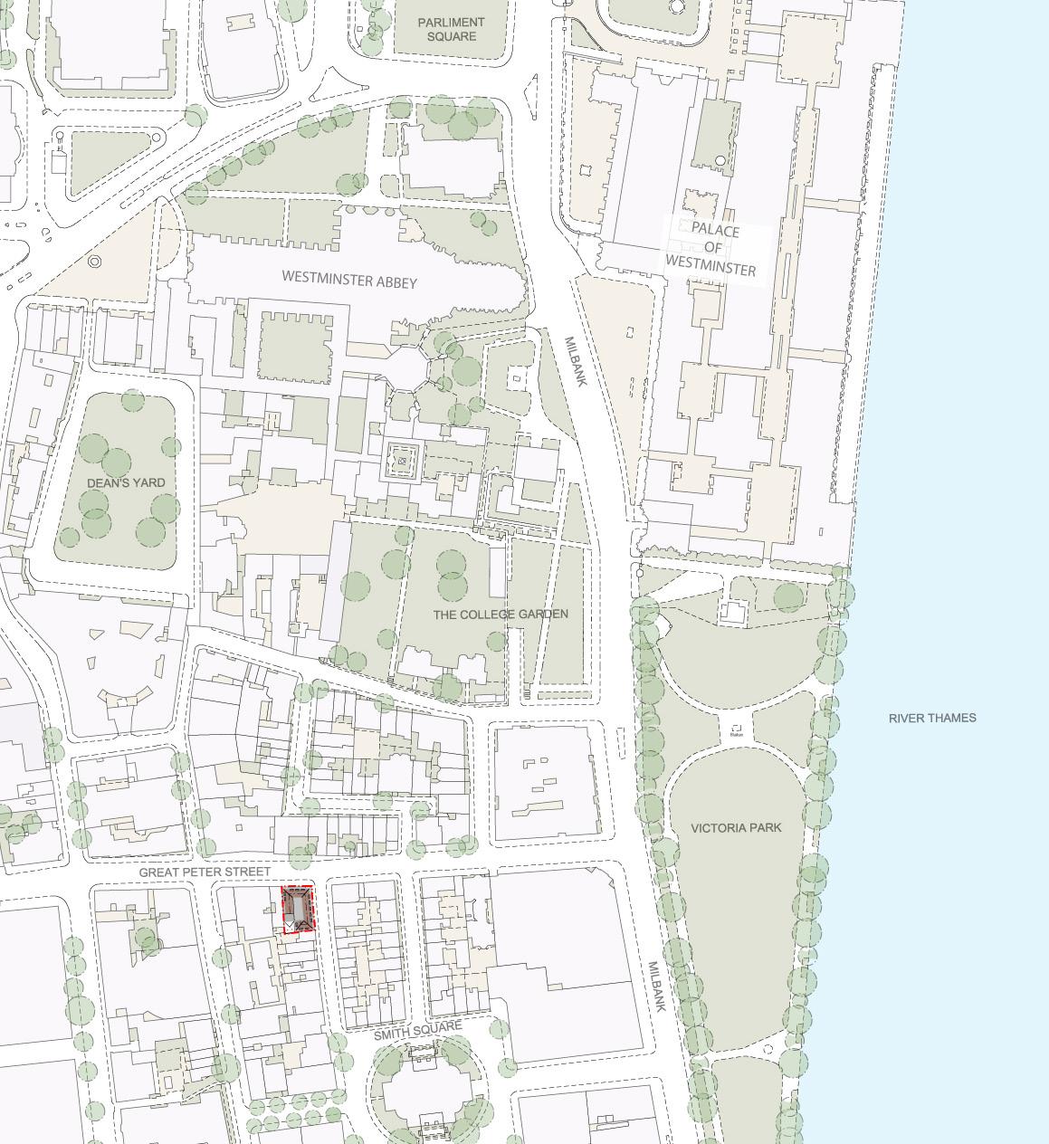
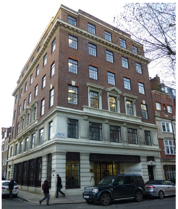
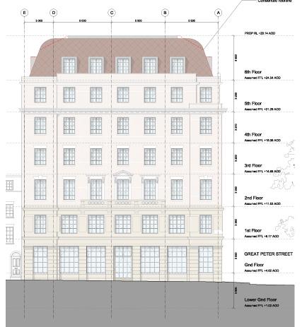
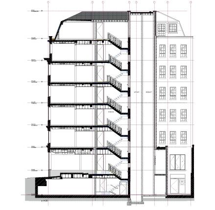
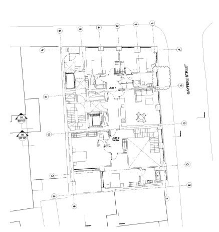
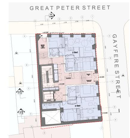
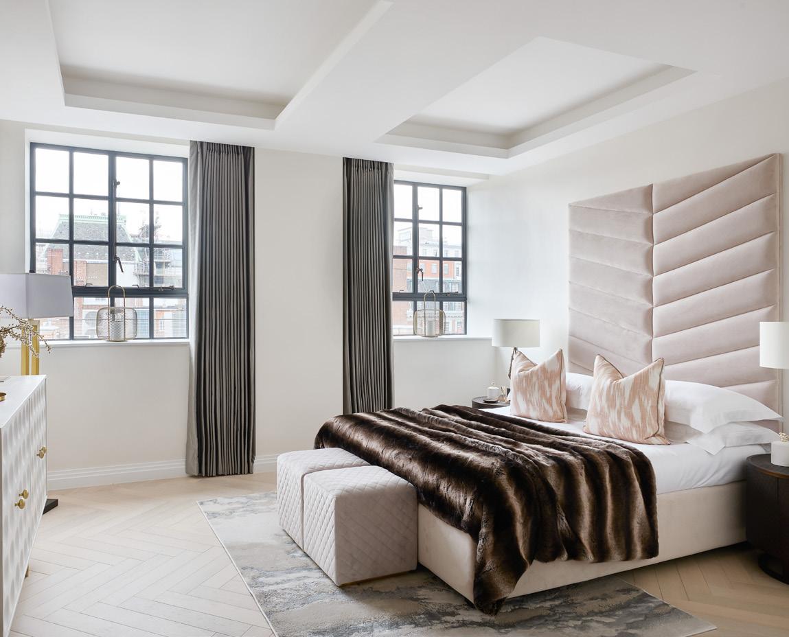
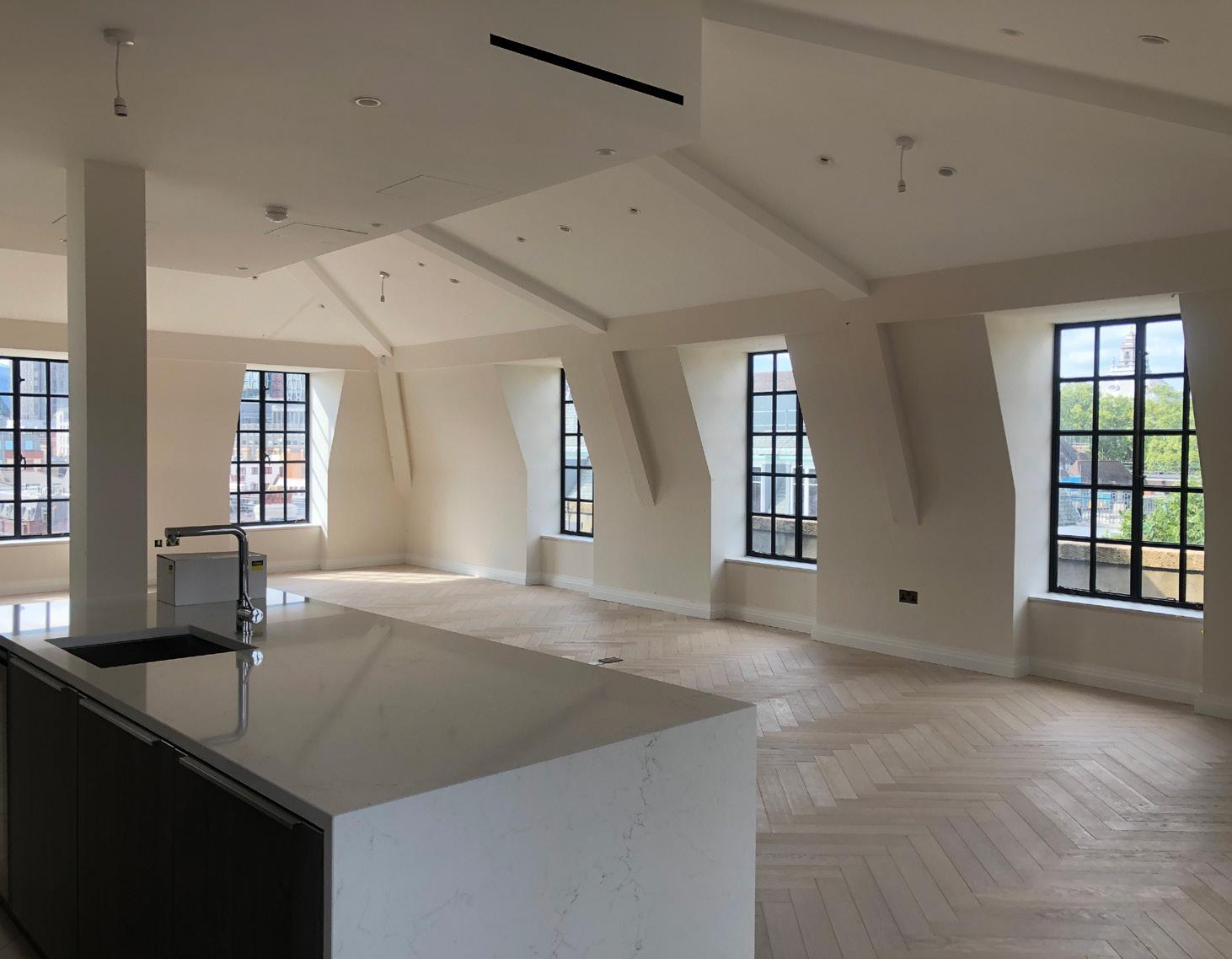
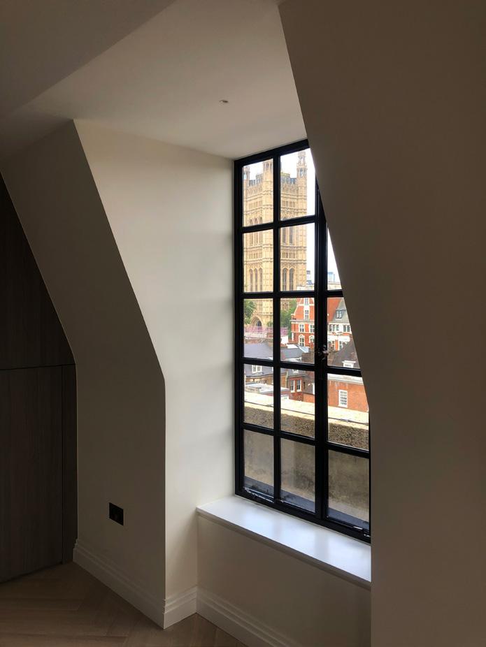
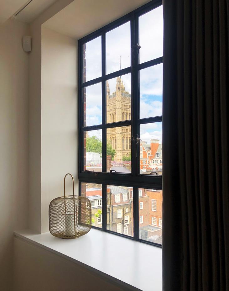
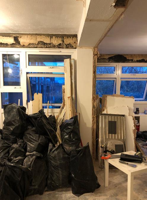
The site is located in a prime area within the City of Westminster, close to the House of Parliament and other major landmarks. Two different schemes have been produced by other architects and have obtained separate planning approvals prior to the appointment of HDAR. The first redesign of the proposed scheme was due to funder feedback to further optimise sale value and reduce the back-of-house to apartment floor area ratio. The second redesign was due to subsequent project finance difficulties induced by contractor bankruptcy and COVID-related project delays. The
proposal maintained the same saleable
demand, and had a
area, featured
and
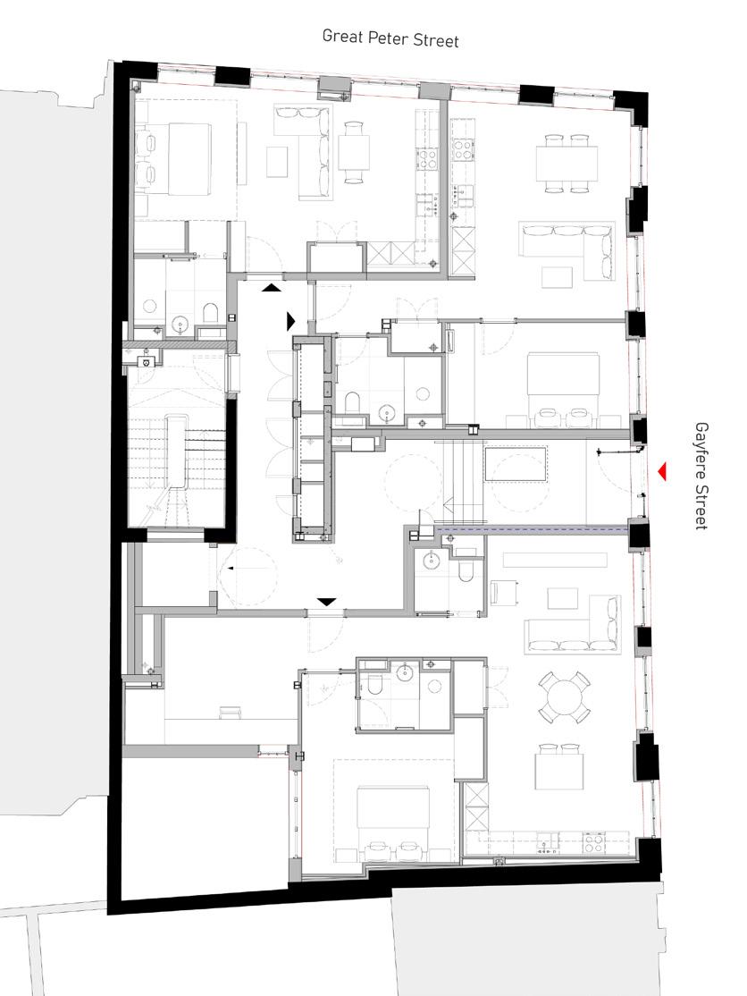
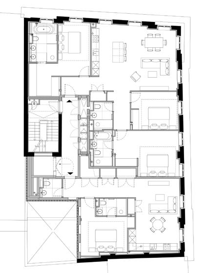
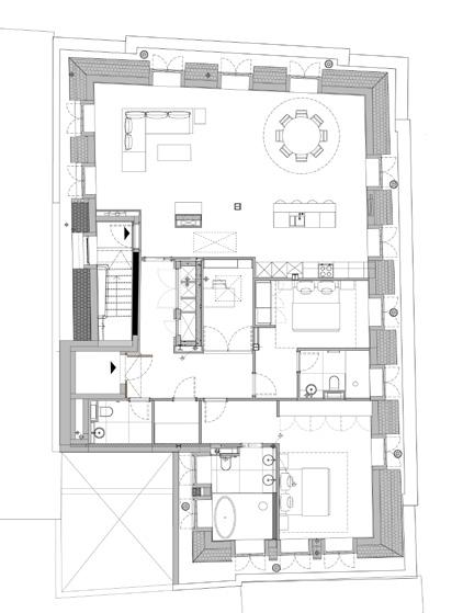
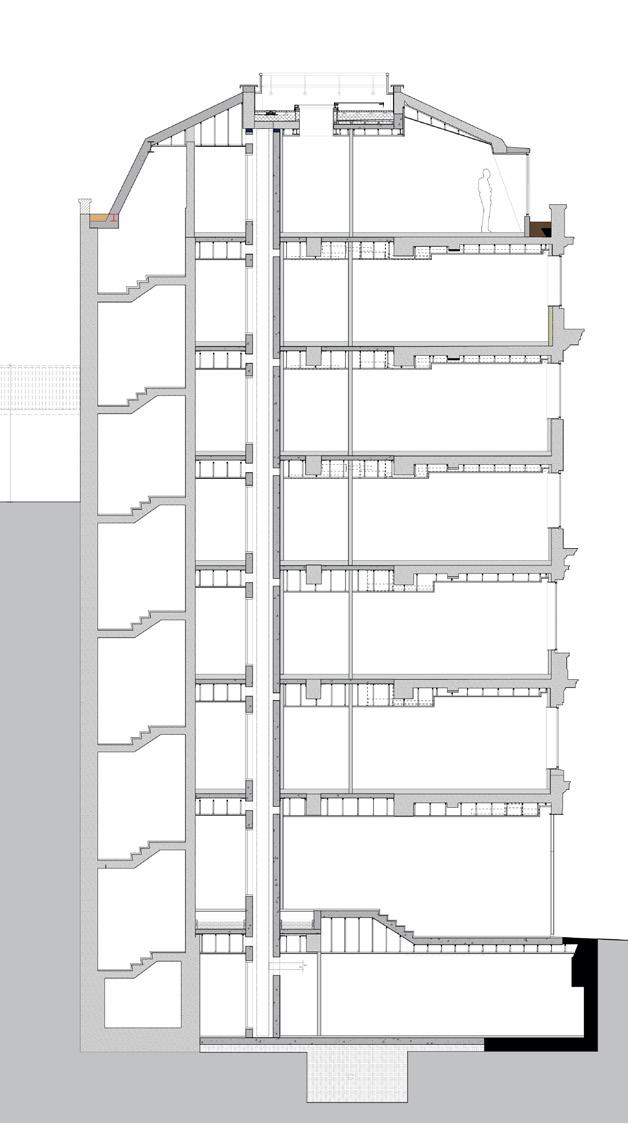
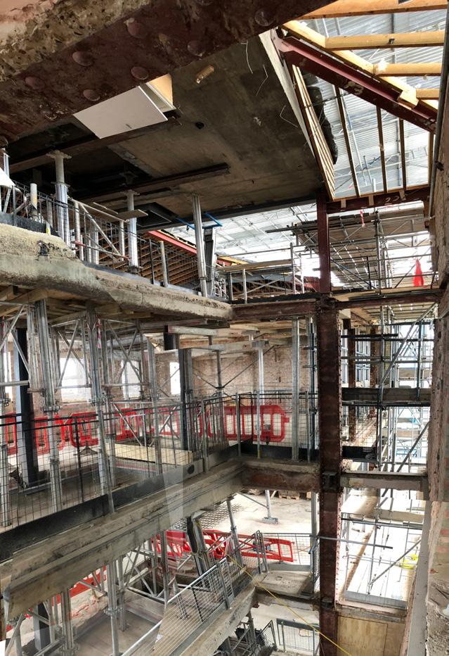
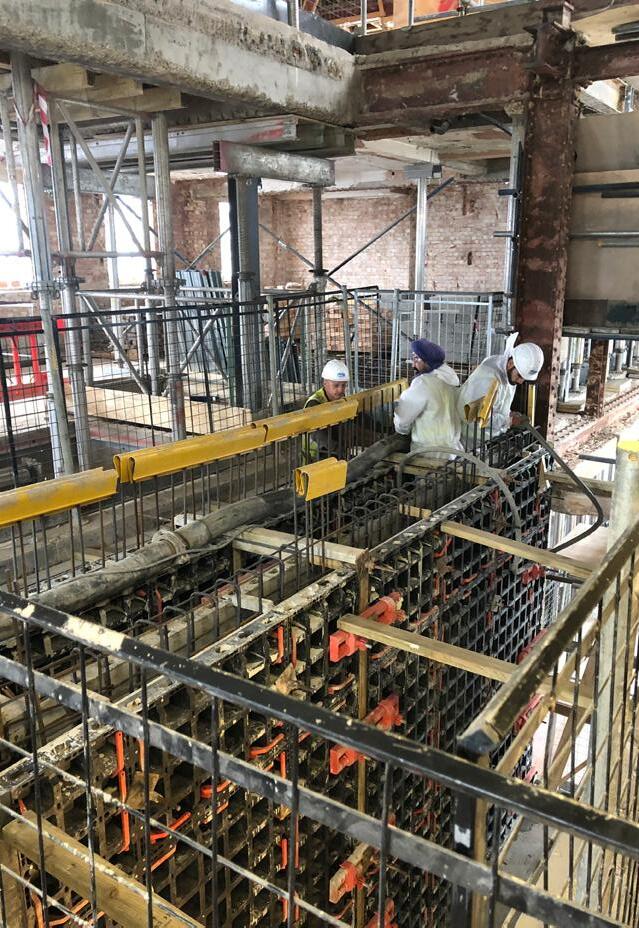
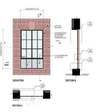
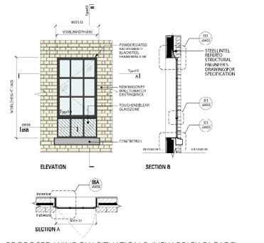
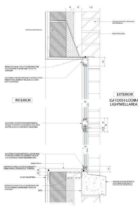
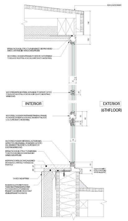
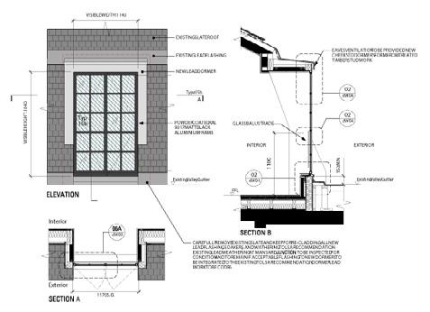
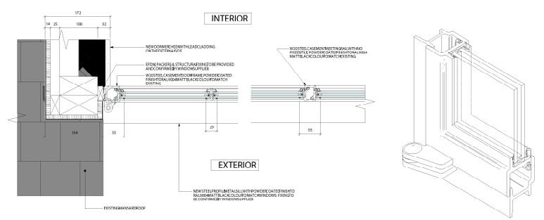
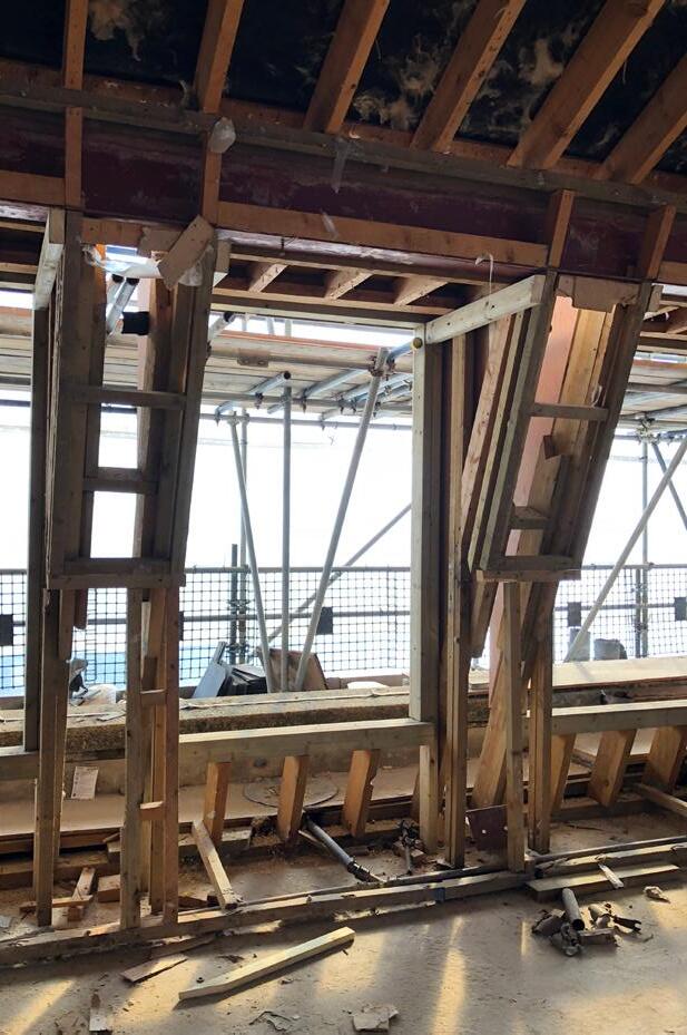
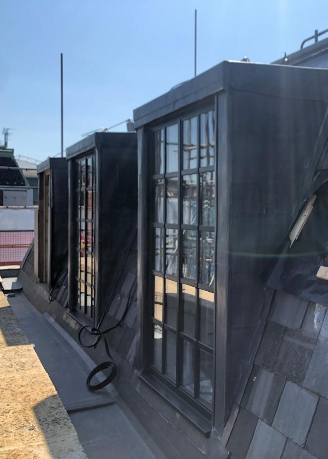
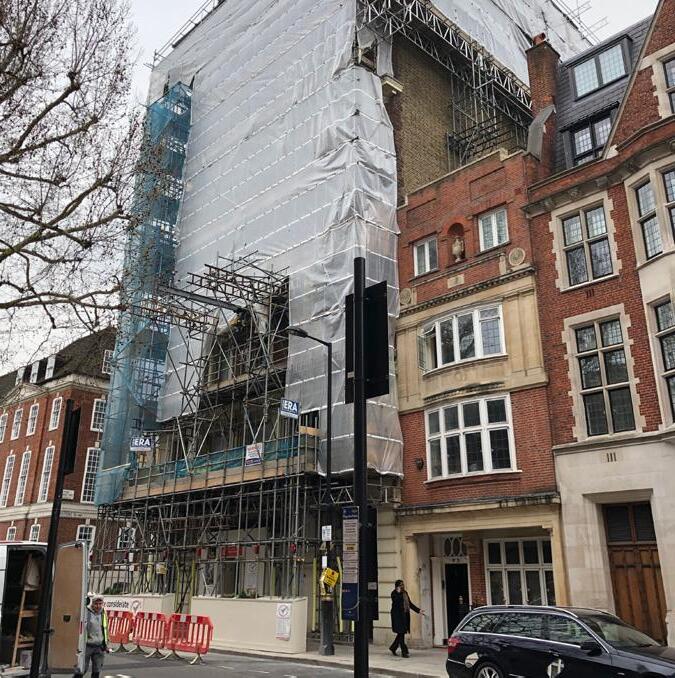
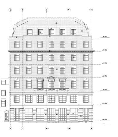
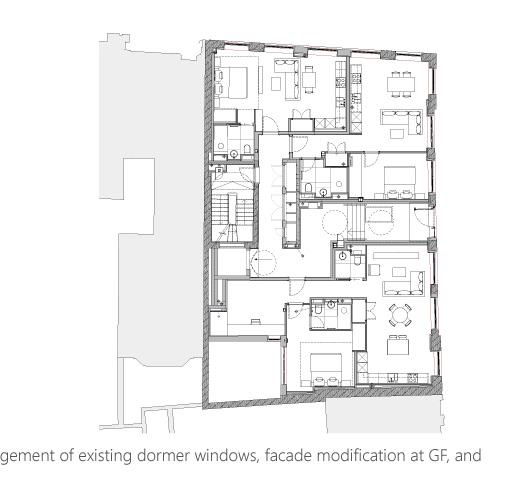
The building is situated in a Conservation Area and adjacent to a Grade II listed building. Therefore, the majority of the original facade is retained to be in keeping with the character of the surrounding context. The main construction works include: 1) the relocation of the central core, extension of the floor plate at the rear facade, and associated structural modifications to allow for more efficient use of floor space; 2) an upgrade to the building envelope and replacement of existing windows to meet the latest energy efficiency regulations; and 3) enlargement of window openings to provide the daylight and sunlight conditions required for residential use.