Download pdf Finite element analysis for design engineers 3rd edition paul m. kurowski full chapter
Finite
Element Analysis for Design Engineers 3rd Edition Paul M. Kurowski
Visit to download the full and correct content document: https://ebookmeta.com/product/finite-element-analysis-for-design-engineers-3rd-editio n-paul-m-kurowski/
More products digital (pdf, epub, mobi) instant download maybe you interests ...
Finite Element Analysis for Design Engineers Second Edition Paul M. Kurowski
Finite Element Analysis and Design of Steel and Steel Concrete Composite Bridges Ehab Ellobody
https://ebookmeta.com/product/finite-element-analysis-and-designof-steel-and-steel-concrete-composite-bridges-ehab-ellobody/ Electric Machines: Transients, Control Principles, Finite Element Analysis, and Optimal Design with MATLAB® 2nd Edition Ion Boldea
Every effort has been made to provide an accurate text. The author and the manufacturers shall not be held liable for any parts developed with this book or held responsible for any inaccuracies or errors that appear in the book.
No part of this publication may be reproduced, stored in a retrieval system, or transmitted, in any form or by any means, electronic, mechanical, photocopying, recording, or otherwise, without the prior written permission of SAE International. For permission and licensing requests, contact SAE Permissions, 400 Commonwealth Drive, Warrendale, PA 15096-0001 USA; e-mail: copyright@sae.org; phone: 724-772-4028
Library of Congress Catalog Number 2022949904 http://dx.doi.org/10.4271/9781468605365
Information contained in this work has been obtained by SAE International from sources believed to be reliable. However, neither SAE International nor its authors guarantee the accuracy or completeness of any information published herein and neither SAE International nor its authors shall be responsible for any errors, omissions, or damages arising out of use of this information. This work is published with the understanding that SAE International and its authors are supplying information but are not attempting to render engineering or other professional services. If such services are required, the assistance of an appropriate professional should be sought.
ISBN-Print 978-1-4686-0535-8
ISBN-PDF 978-1-4686-0536-5
ISBN-epub 978-1-4686-0537-2
To purchase bulk quantities, please contact: SAE Customer Service
E-mail: CustomerService@sae.org
Phone: 877-606-7323 (inside USA and Canada)
724 -776-4970 (outside USA)
Fax: 724-776-0790
Visit the SAE International Bookstore at books.sae.org
Publisher
Sherry Dickinson Nigam
Product Manager
Amanda Zeidan
Director of Content Management
Kelli Zilko
Production and Manufacturing Associate
Brandon Joy
4.5.3.
CHAPTER 5
Finite Element Mesh
5.1.
5.1.1.
5.2.
5.2.1.
5.2.2.
5.2.3.
5.3.
5.3.1.
CHAPTER 6
6.1.
6.1.1.
7.3.
7.4.
7.5. Hands-On Exercises
7.5.1.
8.1.
8.2.
8.3.
8.4.
7.5.3.
7.5.4.
9.4.
9.5.
9.7.
9.8.
9.9
9.10.4. BALL
9.10.6.
9.10.7.
10.6.2.
11.5.4.
CHAPTER 12 Thermal Analysis
12.1. Heat Flow by Conduction
12.2. Heat Flow by Convection
12.3. Heat Transfer by Radiation
12.4. Modeling Considerations in Thermal Analysis
12.5. Challenges in Thermal Analysis
12.6. Hands-On Exercises
12.6.1. BRACKET04
12.6.2.
12.6.3. CHANNEL
12.6.4.
Preface
During the 60+ years of its development, Finite Element Analysis (FEA) evolved from an exotic analysis method accessible only to specialized analysts into a mainstream engineering tool. Progress in computer hardware and operating systems combined with progress in Computer-Aided Design made FEA available to design engineers for use during product design process.
Many books have been written about FEA. At one end of the spectrum, we find books going deep into theory, and at the other end of the spectrum, software manuals explaining how to use a certain program. There is little FEA literature taking a “middle ground” approach and specifically addressing the needs of design engineers who use FEA as an everyday design tool. This book attempts to fill this void by focusing on understanding FEA fundamentals, which are explained by simple yet meaningful examples. “Finite Element Analysis for Design Engineers” takes a practical approach, characteristic of the attitudes of design engineers, and offers the readers an opportunity to try out all discussed topics by solving downloadable exercises using their own FEA program.
Finite Element Analysis is a very broad field of knowledge. Repetitions in discussing concepts, methods, and techniques cannot be avoided. Some topics are discussed more than once, taking advantage of a growing body of knowledge as the reader progresses through the book.
Introduction
1.1. What Is Finite Element Analysis?
Finite Element Analysis, commonly referred to as FEA, is a numerical method used for analysis of structural and thermal problems encountered by mechanical engineers during design is process. It is appropriate to start our discussion with definition of what design analysis and how it relates to FEA. Design analysis is a process of investigating certain properties of parts or assemblies. Design analysis can be conducted on a real object or on models that represent certain aspects of the real object. If models are used instead of a real object, the analysis can be conducted earlier in the design process before physical prototypes are built. The models can be physical models (scale-down models, mock-ups, photoelastic models, etc.) or mathematical models where a certain behavior of the design in progress is captured and described by a mathematical apparatus. Simple mathematical models can be solved analytically. More complex models require the use of numerical methods. FEA is one of those numerical methods used to solve complex mathematical models. The FEA has numerous uses in science and engineering, but the focus of this book is on structural and thermal analysis. We will alternate between two terms and two acronyms that became synonymous in the engineering practice: the Finite Element Analysis (FEA) and the Finite Element Method (FEM).
The FEA is a powerful but demanding tool of engineering analysis. The expertise expected of FEA users depends on the complexity of analysis but always requires familiarity with Mechanics of Materials, Kinematics and Dynamics, Vibration, Heat Transfer, Engineering Design, and other topics found in undergraduate mechanical engineering curriculum. For this reason, many introductory FEA books offer the readers a quick review of those engineering fundamentals. Rather than duplicating the efforts of other authors, Chapter 15 refers readers to some of those books.
1.2. What Is the Place of FEA among Other Tools of Computer-Aided Engineering?
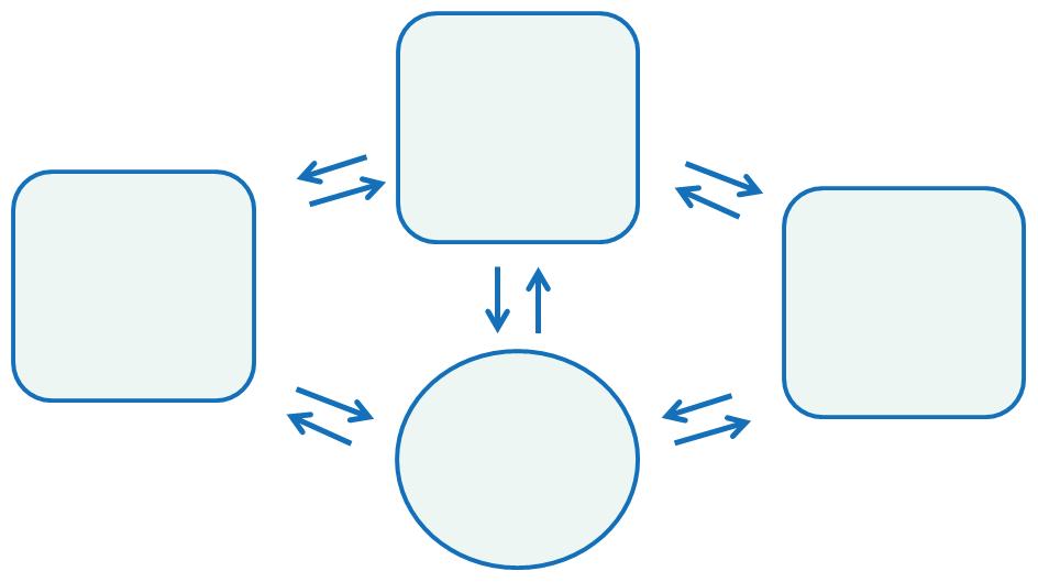
FEA is one of many tools of Computer-Aided Engineering (CAE) used in mechanical design process. Other CAE tools include Fluid Flow Analysis commonly called Computational Fluid Dynamics (CFD) and Mechanism Analysis. These three major CAE tools, FEA, CFD, and Motion Analysis, are integrated with Computer-Aided Design (CAD), which is the hub for all CAE applications. Geometry, material properties, and certain boundary conditions can be exchanged between CAD and add-ins and among add-ins themselves (Figure 1.1). FEA, CFD, and Mechanism Analysis have been developed independently and are based on different numerical techniques; the integration shown in Figure 1.1 is a relatively new development. However, even if CAE tools are stand-alone programs and not add-ins to CAD, they can still be interfaced with CAD.
FIGURE 1.1 CAE applications such as FEA, CFD, and Motion Analysis are add-ins to CAD. They can exchange data with CAD and among themselves.
1.3. Fields of Application of FEA and Mechanism Analysis
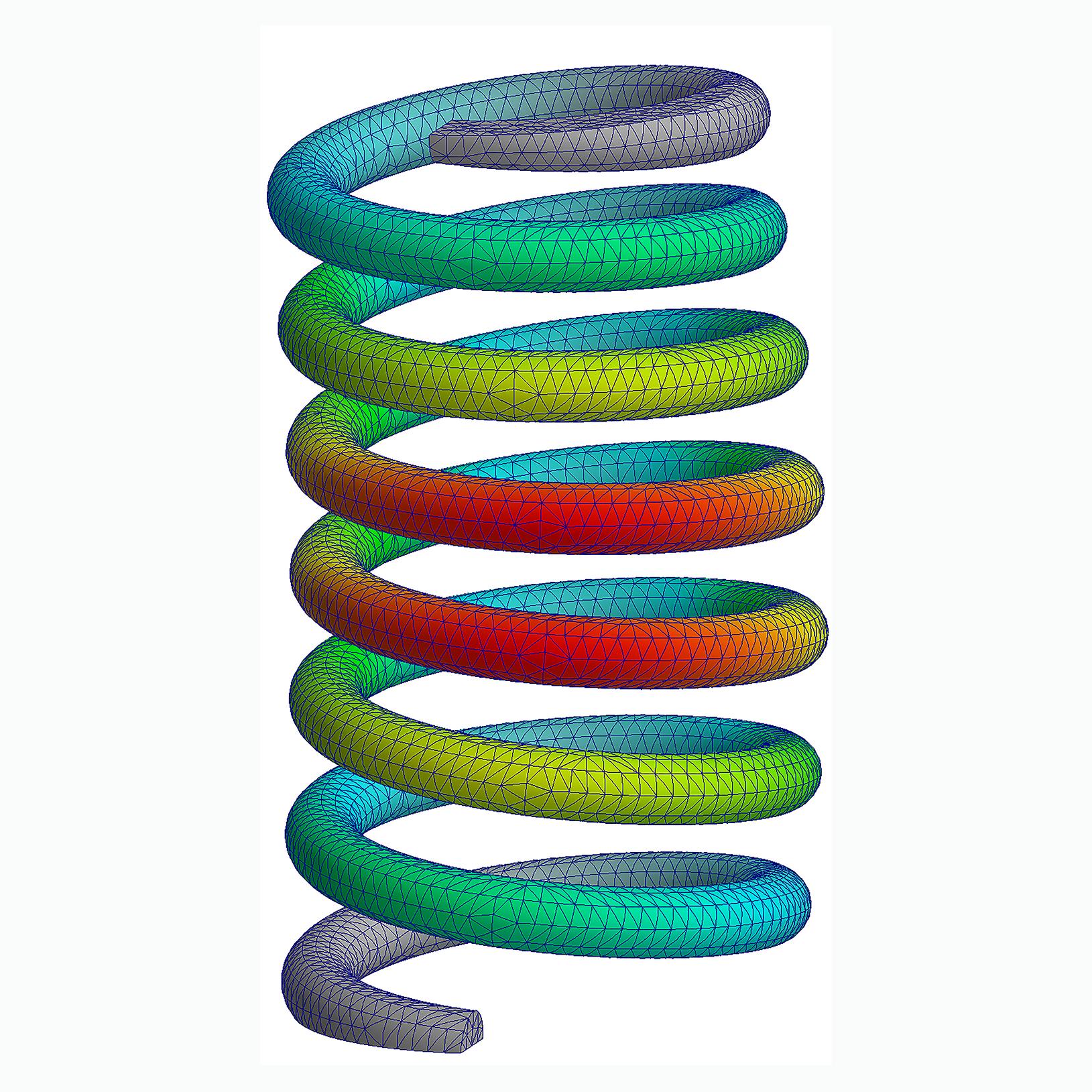
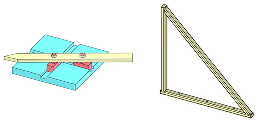
The main difference between FEA and Motion Analysis is the field of application. FEA is used for analysis of deformable objects subjected to loads, and Motion Analysis is used for analysis of motion of mechanisms. A mechanism is not firmly supported and can move without deformation; components of a mechanism can move as rigid bodies. On the contrary, any motion of a structure must involve deformation of its components because a structure is, by definition, firmly supported. The motion of a structure may take the form of a one-time deformation when a static load is applied or oscillations about the position of equilibrium when a time-dependent load is
present. In short, a mechanism may move without having to deform its components, while any motion of a structure must be accompanied by deformation. If an object cannot move without experiencing deformation, then it can be classified as a structure. Examples of a mechanism and a structure are shown in Figure 1.2 .
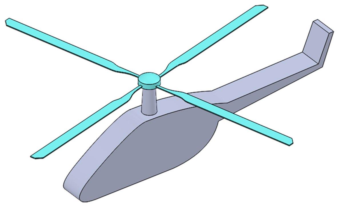
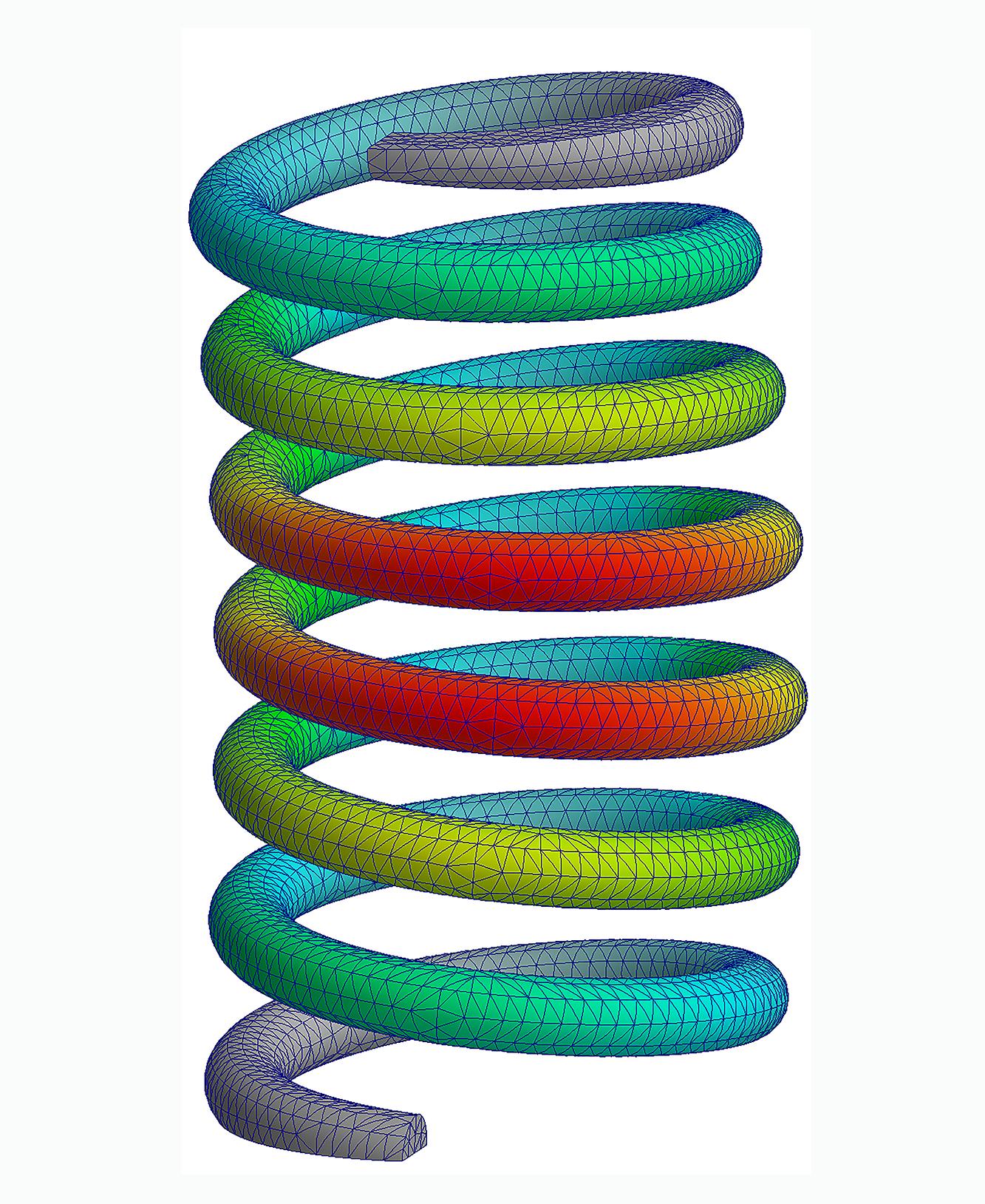
Depending on the objective of analysis, an object or its components may be treated either as a mechanism or as a structure. A helicopter rotor is a mechanism; it spins relative to the hull. A rotor may be treated as a rigid body, assembly of rigid bodies, or assembly of elastic bodies. An individual blade may be treated as a rigid body or as a structure if its vibration characteristics need to be analyzed (Figure 1.3).
A rigid body cannot deform under load; it is a mathematical abstract convenient in mechanism analysis but not applicable to structural analysis.
FIGURE 1.2 An elliptic trammel is a mechanism designed to trace an ellipse when it moves. The motion can be studied without considering deformation of its components. A truss is attached firmly to the ground; it is a structure. It may experience one time deformation under a static load or oscillations about the position of equilibrium under a dynamic load. Any motion of the truss is accompanied by deformations.
FIGURE 1.3 A helicopter rotor can be considered as a mechanism composed of rigid bodies, a mechanism composed of elastic bodies or as a structure.
1.4. Fields of Application of FEA and CFD
In this book we discuss the FEA as a tool of structural and thermal analysis of solid bodies. Heat transfer analysis clearly differentiates FEA from CFD. Heat transfer in solid bodies is analyzed with FEA while heat transfer in fluids requires CFD.
1.5. What Is “FEA for Design Engineers”?
What distinguishes “FEA for Design Engineers” from FEA performed by an analyst? To set tone for the rest of this book, we will highlight the most essential characteristics of FEA performed by design engineers.
• FEA is one of many design tools: For design engineers FEA is one of many design tools and is used along CAD, spreadsheets, catalogs, data bases, hand calculations, textbooks, etc.
• FEA is based on CAD models: A CAD model is the starting point for FEA.
• FEA is concurrent with the design process: Since FEA is a design tool, it should be used concurrently with the design process. It should keep up or, better, drive the design process. Analysis iterations must be performed fast, and since results are used to make design decisions, the results must be reliable even though not enough input data may be available for analysis conducted early in the design process.
• Limitations of “FEA for Design Engineers”: As we can see, the FEA used in the design environment should meet quite high requirements. It must be executed fast and accurately, even though it is in the hands of design engineers and not FEA specialists. An obvious question is would it be better to have a dedicated specialist perform FEA and let design engineers do what they do best: designing new products? The answer depends on the size of organization, type of products, company organization and culture, and many other tangible and non-tangible factors. A consensus is that design engineers should handle relatively simple types of analysis in support of design process. More complex types of analyses are usually better handled by a dedicated analyst.
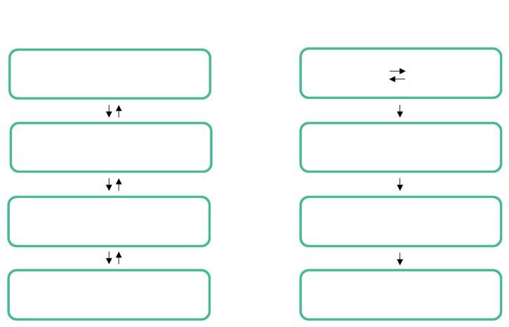
• Objective of “FEA for Design Engineers”: The ultimate objective of using the FEA as a design tool is to change the design process from iterative cycles of “design, prototype, test” into a streamlined process where prototypes are used only for the final design validation. With the use of FEA, design iterations are moved from the physical space of prototyping and testing into the virtual space of computer-based simulations (Figure 1.4). FEA is not the only tool of computer-aided simulation used in the design process. There are others like CFD, Motion Analysis, etc. jointly called the tools of Computer Aided Engineering (CAE).
FIGURE 1.4 Traditional product development needs prototypes to support the design process. A CAE-driven product development process uses numerical models, not physical prototypes, to drive the development process.
TRADITIONAL
CAE DRIVEN PRODUCT DESIGN PROCESS
DESIGN
PROTOTYPING TESTING
PRODUCTION
1.6. Note on Hands-On Exercises
To assure an effective learning, it is necessary to complete hands-on exercises. Therefore, topics discussed in this book are accompanied by simple, yet informative, examples presented at the end of related chapters. The exercises are not specific to any software and can be solved using any commercial FEA program. Completing exercises is essential in the learning process. The list of exercises and downloading instructions are in Chapter 17.
From CAD Model to Results of FEA
2.1. Formulation of the Mathematical Model
To underscore the importance of a mathematical model in the analysis process, it is important to describe what a mathematical model is, where it fits in the design analysis process, and how different it is from the CAD model and the Finite Element (FE) model.
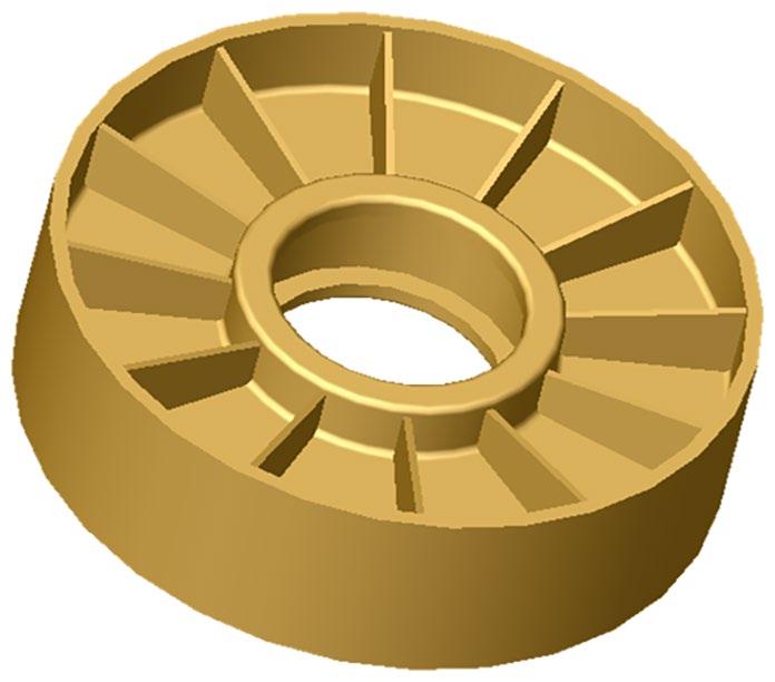
Suppose we need to find displacements and stresses in a pulley. The CAD model defines a volume which is the solution domain (Figure 2.1). The volume has material properties assigned to it and certain conditions are defined on external faces.
The conditions defined on the external faces of a model are called boundary conditions. The boundary conditions can be defined in terms of displacements and loads. Displacement boundary conditions are also called essential boundary conditions, and load boundary conditions are also called natural boundary conditions.
In our example, the displacement boundary conditions are defined on the inner cylindrical face as zero displacement to represent the support provided by a bearing; the bearing itself is not modeled. Load boundary conditions are applied to a section of the outer cylindrical face as pressure and represent the belt load. The above displacement and load boundary conditions are defined explicitly. All remaining surfaces have implicit load boundary conditions: zero stress in the direction normal to the outside faces. This reflects the fact that normal stresses must not exist on an unloaded surface.
FIGURE 2.1 A CAD model of an idler pulley presented as a volume (solid geometry). Representing the model as a volume, and not as surfaces, affords the inclusion of modeling details such as small rounds.
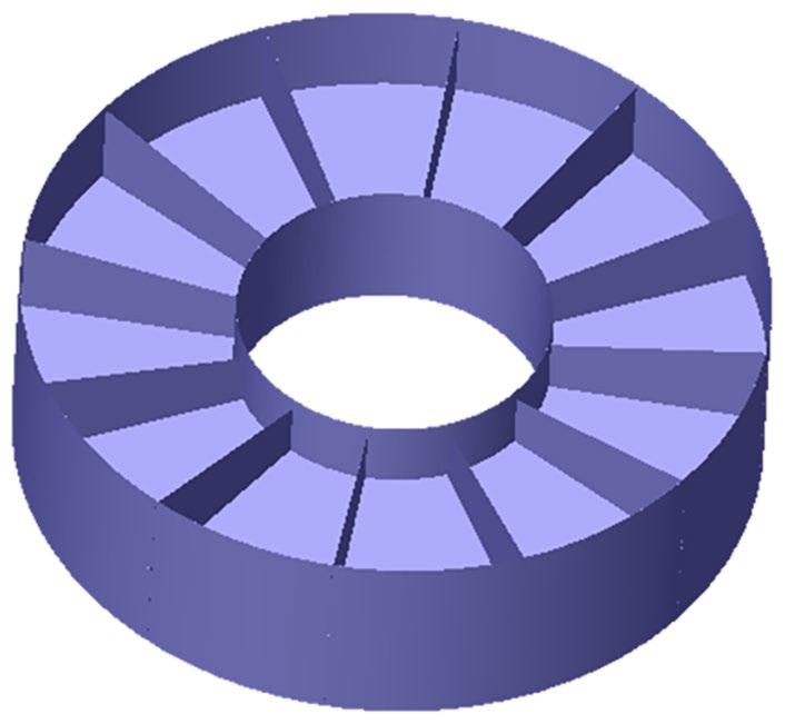
The geometry illustrated in Figure 2.1 is not the only possible representation of the analyzed pulley. Figure 2.2 shows another possibility where a pulley geometry is represented by surfaces. This approach does not allow to model rounds.
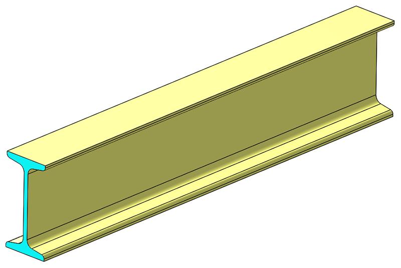
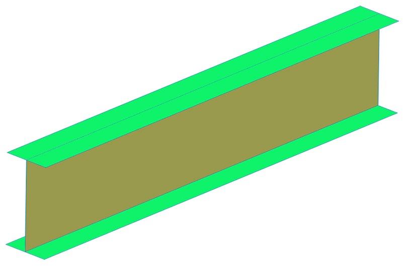
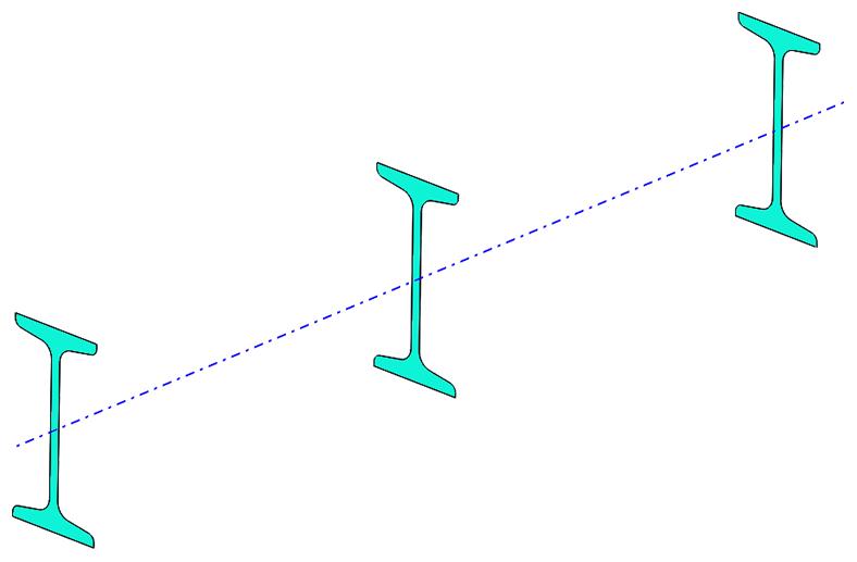
In many analysis problems, more than one geometry representation is possible. A pulley geometry lends itself to being represented with either volumes or surfaces. Modeling a beam offers more choices as the beam can be represented by volumes, surfaces, or curves as shown in Figures 2.3, 2.4, and 2.5
The I beam shown in Figures 2.3, 2.4, and 2.5 illustrate the progressive idealization of a three-dimensional (3D) geometry: from volume (solid geometry) fully representing all three dimensions to surface geometry missing one dimension (thickness) and to curve geometry missing two dimensions.
FIGURE 2.2 The idler pulley geometry is represented by surfaces. The surface geometry is missing one dimension: thickness, which cannot be derived from geometry and must be defined as a number.
FIGURE 2.3 Beam represented by a volume (solid geometry). This affords the inclusion of all details of geometry.
FIGURE 2.4 Beam represented by surfaces cannot include details such as rounds. Representing geometry by surfaces misses one dimension: thickness.
FIGURE 2.5 Beam represented by a curve, shown here as a dotted line. In this idealized model the beam cross-section properties are assigned to curves. The model contains no details and can only represent the global beam behavior. Representing geometry by curves misses two dimensions. Beam cross-section and the second moments of inertia cannot be derived from geometry and must be defined as numbers.