Air-to-air heat pump system enhancing your in-home comfort, one room at a time




Air-to-air heat pump system enhancing your in-home comfort, one room at a time


Hydronics systems are key to better buildings


For more benefits, ask your local wholesaler or visit www.chemfax.com or duboischemicals.com Try Chem-Frost
Safe for all systems (including aluminum and solar)
Premier inhibitors
Higher temperature rated
Phosphate and nitrate free
Low viscosity


Based on information provided on respective manufacturers’ websites*
**Subject to change**

SYSTEM DESIGN
Swing Season Solution
An air-to-water heat pump can satisfy a complete whole home or building’s comfort for all seasons.
By John Siegenthaler

30 MECHANICAL MINUTES Thermal Storage
Webinar review: John Siegenthaler shares insights on trends in maximizing thermal efficiency.
By Doug Picklyk
EDITOR
ASSOCIATE PUBLISHER
NATIONAL ACCOUNTS
ACCOUNT COORDINATOR
MEDIA DESIGNER
CIRCULATION MANAGER
PUBLISHER
CEO
Doug Picklyk (416) 510-5218 DPicklyk@hpacmag.com
David Skene (416) 510-6884 DSkene@hpacmag.com
Amanda McCracken (647) 628-3610 amccracken@hpacmag.com
Kim Rossiter (416) 510-6794 KRossiter@hpacmag.com
Emily Sun esun@annexbusinessmedia.com
Urszula Grzyb (416) 442-5600, ext. 3537 ugrzyb@annexbusinessmedia.com
Peter Leonard (416) 510-6847 PLeonard@hpacmag.com
Scott Jamieson
INTEGRATED DESIGN Efficiency in Every Drop: Part 1

As modern buildings strive for energy and environmental efficiencies, along with a healthy indoor environment, hydronics and heat pumps will play a major role in the solution.
By Zachary Londo, Jean-Claude Rémy & Chris DesRoches
CONTROLS CurtGPT: Ask Anything (about hydronics)
A real person’s response to a real person’s question about the effects of glycol in a hydronic heating system.
By Curtis Bennett

DESIGN
Old World, New World
Adapting a tried-and-true wood-fired heating system to work with modern technology.
By John Siegenthaler


Backed by industry leading technology, The HPX™ Air-to-Water Heat Pump is the perfect solution to year round comfort. Pair it with the SKy-35 control to optimize your comfort, operating costs and energy consumption.


An air-to-water heat pump can satisfy a complete whole home or building comfort solution for all seasons.
BY JOHN SIEGENTHALER
Hydronically-heated concrete floor slabs can deliver silent, steady, and superior comfort. Their high thermal mass can dampen out reasonable variations in heat input to an extent that occupants are unaware that such variations even exist. The same thermal mass can also deliver “full afterburner” heat output when cold outside air slides over the heated floor from an open overhead door. That burst of heat output quickly restores comfort when that door is closed.
The concept that the floor slab can act as a thermal storage device to absorb heat from sources such as a heat pump running on low-cost off-peak rates is also an attractive quality, and one that has the potential to keep hydronic-based sys -
tems highly relevant as utilities plan how to meet future electrification goals.
So, what’s not to like about heated floor slabs?
Well, imagine this scenario: it’s a cool rainy day in early fall as a cold front moves through dropping the outdoor temperature to 7C/45F for a short time. The air is damp and the heated slab system has not yet been turned on for the season. The weather forecast is for sunshine and temperatures in the mid-20s to return the next day.
Should that floor slab heating system be turned on to chase the chill away for the next few hours?
Consider some Western Canadian locations where the overnight temperature in early fall drops to just above freezing, but “Chinook winds” and sunshine the following day bring the outdoor temperature into the upper 20s causing the building’s cooling system to kick in the following afternoon.
Should that slab heating system be turned on during that cool, but short-lived, overnight period, knowing that “summer
like” conditions are only a few hours away?
Let’s assume the answer to these two questions is “Yes.”
The occupants, feeling slightly uncomfortable, flip the switch to start the system. If the water temperature supplied to the floor circuits is controlled based on outdoor reset control, the supply temperature might only be in the upper 70s F to mid-80s F (20 to 30C) range when the outdoor temperature is 45 to 50F (7 to 10C).
Although those water temperatures are above the room temperature, the difference is small. It’s going to take several hours for the floor to make much improvement in comfort. By the time the floor warms the load could be eliminated by warmer outdoor temperatures, or by the internal heat gains from sunlight, people, etc.
If cooling is required by the afternoon, any heat that continues to percolate from the floor surface just adds to the cooling load.
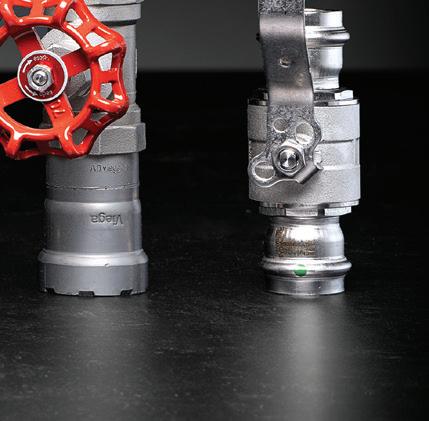
MEGAPRESS ® FKM AND MEGAPRESS 316 GLOBE VALVES
The only press globe valve with Iron Pipe Size (IPS) ends. Viega globe valves are engineered for precise flow control, offering a rising stem and multi-turn design that allows for visual confirmation of the valve’s open or closed position. These valves are an ideal solution for systems that require more precise modulation, unlike quarter-turn valves.


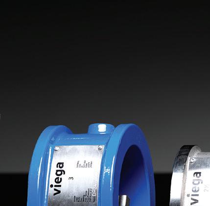
MEGAPRESS 316 AND PROPRESS ® BUTTERFLY VALVES
A simple and reliable solution for flow isolation and control in commercial and industrial plumbing systems. Available in sizes 2 ½" to 4", these valves are designed for compatibility with Viega ProPress and MegaPress flange adapters, ensuring a secure and efficient connection. They are available in 316 stainless steel and epoxy-coated ductile iron materials and are NSF 61 approved for potable water systems.
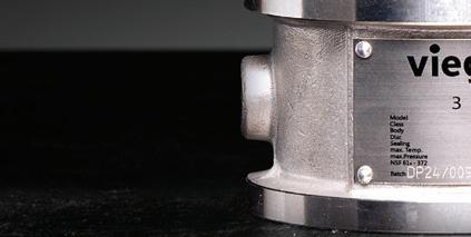
PROPRESS AND MEGAPRESS WAFER CHECK VALVES
Engineered to prevent reverse flow, these valves feature a dual-disk design that promotes a streamlined flow path, reducing pressure drops and increasing energy efficiency. Available in sizes 2 ½" to 4", these compact valves are optimized for use with Viega MegaPress and ProPress flanges. They are available in 316 stainless steel and epoxy-coated ductile iron materials and are NSF 61 approved for potable water systems.








Wouldn’t it be nice to have a system that can quickly warm the interior air, without waiting for hours as the floor slab slowly warms?
Imagine a hydronic system with a “first gear” to quickly accelerate the space to some degree of comfort, as well as a “high gear” to keep that comfort cruising along during the dead of winter.
Consider the system shown in Figure 1.
This system uses a monobloc air-towater heat pump as its lead heat source. An electric boiler provides supplemental and backup heating when necessary.
Both heat sources supply a reverse indirect tank that serves as a buffer for supplying stable domestic hot water, as well as a hydraulic separating device for all four circulators in the system.
This tank can also buffer a small space heating load - to be described shortly.
When the heat pump is first turned on in heating mode, the bypass zone valve (MV3) is open, and motorized ball valves (MV1) and (MV2) are closed. This allows the fluid to recirculate back through the heat pump until it reaches a temperature just above that in the upper portion of the tank.
At that point (MV1) opens and the bypass valve closes. Heated fluid is delivered to the reverse indirect to maintain its temperature between 115 and 125F (46 and 52C).
A similar control scenario is used when the heat pump turns on in cooling mode. The bypass valve is open and both (MV1) and (MV2) are closed.
The fluid recirculates through the heat
pump and quickly reaches a suitable temperature for cooling. At that point (MV2) opens, the bypass valve closes, and chilled fluid is delivered to the coil in the air handler.
Flow through the air handler’s coil is provided by the same circulator (P1) that creates flow through the heat pump.
If the heat pump has a variable speed compressor its cooling capacity is regulated to maintain a pre-set supply temperature to the coil - typically in the range of 45 to 55F (7 to 12C).
There are two heating load circuits on the right side of the tank. One goes to the air handler, the other supplies the high thermal mass floor heating system.
Circulator (P3) provides a flow of warm


Navien introduces its full line of HVAC products, featuring new NAZ Heat Pumps, NAS Air Handlers, NAM Cased Coils, and other forced-air components. Deliver a whole-home AHRI matched Navien comfort system when pairing with the NPF Hydro-furnace, including a powerful dual-fuel system with gas-powered NPF and the NAZ Heat Pump.
To learn more about Navien HVAC comfort, visit us at navieninc.com.
fluid from the upper portion of the tank to the coil in the air handler. This is the “rapid response” heating method for those cool/damp fall days.
Ideally, (P3) is a variable-speed circulator that responds to the air temperature leaving the air handler. The faster the circulator runs, the warmer the leaving air temperature. Variable-speed “setpoint” circulators have been available on the market for several years, and they are ideal for this application.
After passing through the coil the cooler fluid returns to the lower portion of the indirect tank. Some or all of the flow leaving the coil might also go to the heat pump if it’s operating.
The high thermal mass floor heating system is also sourced from the upper portion of the tank. The supply temperature to the floor circuits is regulated by a motorized “injection” valve (IV), which is controlled based on outdoor reset. The greater the flow rate passing through the valve, the warmer the supply temperature to the floor circuits.
A simple two-stage temperature setpoint controller operates the air-to-water heat pump - or if necessary - the electric boiler, to maintain the upper portion of the tank between 115 and 125F (46 and 52C).
That’s high enough to provide reasonable DHW delivery at 110F, and it’s also well within the operating range of modern air-to-water heat pumps, especially those operating on R-32 or eventually on R-290 (propane).
Modern homes built to ever-tightening energy codes often require mechanical ventilation. The preferred method for exchanging stale air for fresh air is through a heat recovery ventilator (HRV).
Figure 1 shows an HRV tapped into the return side of the air handler. This ventilator draws air from the bathrooms, extracts up to 70% of the heat from that air, and transfers it to the incoming fresh air stream.
That “conditioned” fresh air is then injected at the return side of the air handler.
A typical ventilation rate for a modest single-family home is 5 cubic feet per minute (CFM) per 100-square-feet of floor area. This equates to 125 CFM for a 2,500 sq. ft. house. That’s well below the air flow rate of 250-300 CFM per ton of cooling.
A typical 3-ton rated air handler could be operated at 750-900 CFM to distribute the fresh air to all supply diffusers in the building, but doing so increases the power demand of the blower higher than necessary when only ventilation (and not cooling) is required.
Modern blowers with electronicallycommutated (EC) motors often have speed tappings allowing them to operate at lower flow rates in the range of what the HRV produces. This minimizes power input while distributing the fresh air through the same ducting system used for cooling.
A different motor speed tapping is activated to provide the higher air flow rates required for cooling.
Consider a situation in a cold northern climate where the outdoor temperature is -10F (-23C). If the HRV recovers 70% of the sensible heat from the outgoing 70F (21C) air, the incoming fresh air stream leaves the HRV at about 46F (7C). That’s still pretty cool to be introduced directly into occupied space.
This is where the variable speed setpoint circulator (P3) can provide additional functionality. It can operate to create a small flow rate of heated fluid through the air handler coil to boost the incoming 46F fresh air up to a neutral temperature in the range of 70 to 75F (21 to 24C) before that air is introduced into occupied spaces.
Since a monobloc heat pump is being used the entire system needs to operate with an antifreeze solution. This protects the heat pump during a power outage, or
other situation when it remains off for several hours at sub-freezing outdoor temperatures. It also provides freeze protection for the air handler’s coil.
Consumers have lots of choices when it comes to HVAC systems. Contemporary systems such as ductless mini-split heat pumps are incessantly pushed as being a “state-of-the-art” solution. In reality, these heat pumps provide forced air heating and cooling, but not domestic water heating nor heat recovery ventilation. They’re a “partial” solution.
The system shown in Figure 1 provides that complete HVAC solution. It’s well suited to modern “electrified” homes, and it can be assembled from readily available components.
It’s a system that demonstrate that hydronics technology is not passé, but rather “cutting edge” in its versatility, energy efficiency, and its ability to deliver superior comfort.
It’s up to us — the North American hydronics industry — to keep hydronicbased systems relevant amidst all the marketing efforts for competing HVAC options.
It’s up to us to educate homeowners, builders, architects, and energy consultants how a hydronic-based system, using multiple function air delivery subsystems, can provide complete solutions for HVAC using the latest heat pump technology.
Collectively we have the technology to provide superior and complete solutions for HVAC. Learn it, believe it, design it, and sell it.

John Siegenthaler, P.E., has over 40 years of experience designing modern hydronic heating systems and is the author of Modern Hydronic Heating (4th edition) and Heating with Renewable Energy (visit hydronicpros.com).
Easier, fast er ins t alla t ion & opt imum per for mance design


Suitable for multiple PE X tube diameters Easyto assemble
Amvic Insulat ed PE X panel is designed to pr ovide the most cost -effec tive ins t allat ion and per formance f or hydr onic radiant f loor heating syst ems for new cons truc tion and r enovat ions.
Ideal for basement s, car ga rages, slab-on- grade ar eas and exterior use f or snow and ice melt applicat ions on dri veways and walk ways.
Save time, labour and money
Walk in inst allation
No st aples or ties required
Superior tube insulation
Integrated vapor barrier
Available for r esidential and commer cial

We speak with John Siegenthaler about the evolving role of thermal storage and hydronics systems.
BY DOUG PICKLYK

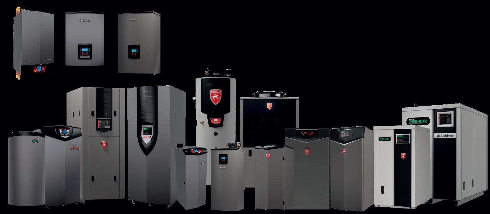
Once again, longtime HPAC Magazine contributing writer and hydronics industry expert John Siegenthaler joined us for a recent edition of 30 Mechanical Minutes, the free live webinar series. This episode tackled the topic of thermal storage and the role it plays in hydronics systems. This edition was sponsored by Lochinvar and Aqua-Tech Marketing Solutions, the Lochinvar master distributor across Canada (except Quebec).
To begin, Siegenthaler shared how the concept of storing thermal energy has been associated with hydronics for decades and how it’s commonly used in applications like biomass boilers and with solar thermal systems to collect the heated water and store it for distribution when required.
The concept is now evolving with the drive to decarbonize heating systems and incorporate more electrification into hydronic heating solutions. As Siegenthaler explains, “When it comes to electrification, electrical utilities are introducing time-of-use rates, so we can use electricity when it’s at its least expensive.”
As he explains, in a hydronics system, designers can incorporate water-to-water or air-to-water heat pumps and save money by running the units in off peak times and storing the heat energy for use when it’s required.
“One of the unique characteristics of hydronics versus forced air is the very high thermal storage potential of water,” notes Siegenthaler. “A given volume of water can hold almost 3,500 times as much heat as the same volume of air with the same temperature change.”
To illustrate the cost saving potential, he shared how one utility has an on-peak cost of electricity of 44 cents a kilowatt
hour, and the off-peak rate is 7 cents a kilowatt hour— almost a 7 to 1 rate differential.
He compares that to a gas station selling gas at $3.30 a gallon in the daytime, and then at 2 o’clock in the morning marking it down to 55 cents a gallon. People would fill their tanks whether they need to or not.
This is where the thermal storage comes in for heating buildings. He shared a slide showing a system design schematic with a monoblock air-to-water heat pump using a mixture of antifreeze and water as the primary heat source. The distribution system leads to panel radiators suitable for low temperature supply water and also to a storage tank as well. The design shows the required valving and three circulators can all be controlled to direct the flow in three different modes.
In one mode the heat pump would flow direct to the heat emitters. Alternatively, at times when the cost of electricity is low (typically night times, weekends or major holidays) valves would open and close to send the heated fluid into the top of the thermal storage tank, what Siegenthaler calls “the charging mode.”
And the final mode would be when the heat pump is off and a circulator draws water from the top of the tank, through a hydraulic separator and out to the load, and the return water returns to the bottom of the tank.
Siegenthaler then shared details of a research project he has been involved with focused on using very low operating cost systems in a cold climate without ever losing comfort in the building. In one example the researchers are using a cascading heat
pump system with a standard outdoor condenser unit with a refrigerant line set that goes inside a house to another heat pump. The first one lifts the outdoor temperature to an intermediate temperature, and then that refrigerant gets boosted further and a heat exchanger transfers the heat to the water. “We’ve actually seen these things operate over 180F water temperature,” he notes.
Part of the project is to take advantage of the lowest cost electrical energy being offered by utilities using connected software. He explains that as utilities add more large-scale renewable electrical generation to grids (wind and solar), the challenge is not the lack of energy generation, it’s the inability to fully utilize the peak output.
When large-scale solar or wind farms generate more electricity than the grid can handle, rather than curtail generation utilities want to sell that power at a
wholesale rate to other utilities. And they encourage that sale by changing (lowering) their price structure.
And utilities operate with lots of data in order set the pricing, and there are times when the price structure at the wholesale level can be negative (they pay for you to take it off their hands).
This is where these research projects are using a sophisticated algorithm tied to the utility, knowing what the next 48-hour pricing schemes will be on an hour-byhour basis it can determine what the best operating mode will be for the heating system. Should you run the heat pump? Should you draw from thermal storage?
Calculations are continuous. He notes that this is a proof of concept project, but he feels there’s a very good chance it will come to market one day.
He adds that a lot of North America does want cooling now as well, so he also believes that it’s very important that systems
be designed so cooling can be added. And of course there is also the option of adding domestic hot water to a system as well.
The webinar also addressed alternative forms of thermal storage, namely phase change materials and solid-based thermal storage. While Siegenthaler sees a growing interest in alternative methods for storing thermal energy, he sees the tank based solution as cost effective if the building has the required space.
The webinar included a question-andanswer period with topics ranging from storage tank design to questions about heat pumps and new refrigerants.
To view the entire webinar video including the question and answer section, or to revisit any past episode of 30 Mechanical Minutes, visit hpacmag.com/webinars, or visit the HPAC Magazine YouTube channel, @hpagmag. <>


– PART 1
As modern buildings strive for energy and environmental efficiencies along with a healthy indoor environment, solutions will be achieved though hydronics and heat pumps. (Part 1 of a 4-part series.)
BY ZACHARY LONDO, JEAN-CLAUDE RÉMY & CHRIS DESROCHES
Designing HVAC systems for buildings within today’s modern regulatory frameworks has never been more challenging. What started in the early 2000’s as a drive towards energy efficiency and sustainability has transformed to encompass much more.
Holistic building designs must now meet stringent performance requirements implemented at municipal, provin -
cial and federal building and energy code levels including energy use intensity (EUI), thermal energy demand intensity (TEDI), and greenhouse gas emission intensity (GHGI). Meeting these metrics within the heating, ventilation and air conditioning systems means we can no longer design hydronics and air systems separately, the best efficiencies come from an integrated approach.
Fortunately, constantly evolving tech -
nology now provides designers more choices than ever to achieve the above criteria. The market has accepted that heat pumps, in whichever shape or form they may take, are here to stay. Heat pumps provide an electrified means to heat our spaces, and some also offer cooling capabilities. They are instrumental tools to not only decarbonize but achieve efficiencies greater than 100% to reduce energy consumption.
That’s why heat pumps are instrumental to achieve Net-Zero or Net-Zero-ready building targets for new buildings by 2030, and they will play a key role for retrofitting existing building stock in Canada by 2050.
When it comes to new buildings, voluntary performance programs such as LEED, Passive House and others have been gaining popularity over the last decade. The principles of these performance standards are quickly becoming


Introducing Sequoia, a high voltage immersed electrode hot water boiler designed for large commercial and industrial applications. A cleaner, more sustainable solution for your decarbonization efforts.
Zero emissions • 97% efficiency • Cleaner, safer operation with no combustion hazards
Compact footprint • Long-life, low-maintenance electrodes • 2500-60000 kW
aerco.com/sequoia | sales@aerco.com
mandatory at the federal, provincial and municipal levels on the path to 2030 and 2050.
The associated indoor environmental quality (IEQ) and occupant health benefits of a well-designed building are often forgotten and overlooked, but comfort and IEQ can be achieved while meeting or even exceeding energy and carbon efficiency goals.
You can have it all. Both the mechanical design of the system and the building parameters, such as ventilation strategies, building insulation and airtightness, must be planned in synergy with the mechanical design to meet these goals, without sacrificing comfort.
Think about it, you can design the most efficient building there is, but if occupants are not comfortable and open a window to seek comfort then there go your savings, right out the window. Literally.
On top of these rapid changes, embodied carbon is quickly coming into the picture. Embodied carbon is the carbon emission associated with the materials and products used to construct the building, including manufacturing and transportation of these materials, as well as the downstream embodied emissions such as: refrigerant leakages, repairing or replacing the mechanical system to get them operating properly, and through to the disposal of materials and equipment at the end of their life cycles.
Embodied carbon is one of the key reasons the refrigerant R-410A is being phased out. One kilogram of R-410A has the equivalent greenhouse gas (GHG) emissions of 2,088 kg of CO2 equivalent.
Europe transitioned away from high global warming potential (GWP) refrigerants in 2017 moving to medium-GWP refrigerants like R-32 and R-454B for heat pump applications, which are classified as A2L, meaning they are mildly flammable.
In North America, that transition just

started in 2025. This means that designing with these new refrigerants adds another layer of challenges when safety is considered. Mildly flammable refrigerants are leading practitioners to rethink the idea of having these systems contained within the building.
Nobody wants undetectable, flammable refrigerants leaking in their building without the systems properly designed and mitigated to ensure safety codes are met. Distributed refrigerant systems will still be used during this transition, but meeting the requirements to use them safely in the building adds to the design complexity and increases the installation costs of the system. This is a key factor that is driving our market back to hydronics with use of these refrigerants in packaged equipment installed outdoors and water to move the energy throughout the building.
Navigating through this web of requirements has never been more challenging and is radically changing the mentality of the design market to reconsider what a building will look like in 2030. All these factors lead to a simple conclusion of one clear frontrunner for mechanical systems: hydronics.
Advancements in hydronic heat pump technologies, like water-source and airto-water central heat pumps, have come a long way in recent years. With larger compressor equipment using liquid or vapour injection now available and certified for North America, today’s air-to-water heat pumps offer reliable operation and performance at ambient temperatures as low as -20C or lower. With properly sized heat pumps and well-calculated heating and cooling emitters, hydronics not only provides a low-carbon solution for the building but improves energy efficiency and comfort while removing refrigerants from the occupied spaces.
This four-part series of articles will demonstrate how hydronics is quickly becoming the preferred solution for buildings. Practitioners should consider the four pillars of building design: building envelope, indoor air quality, heat/cooling emitters (primary and in some cases supplemental heating and cooling emitters-ventilation, convection or radiation), and control strategies. When all four pillars are applied holisti -
cally and as part of an integrated design process, we can enable low-temperature heating and high-temperature cooling to boost efficiency outcomes and improve comfort.
The first, and most important component is the building envelope. An underperforming envelope, driven by a low R-value or poor sealing requires running the heating/cooling and ventilation systems at a higher load and for longer, resulting in more energy use.
“All these factors lead to a simple conclusion of one clear frontrunner for mechanical systems: hydronics.”
If we have a high performing and efficient HVAC system but a leaky building, then nothing is gained. By focusing on envelope improvements first, you create a space with lower mechanical requirements; this improves overall efficiency, drives down operational costs, reduces energy usage, and strengthens resiliency in extreme weather events.
These lower mechanical requirements also enable practitioners to take advantage of low-temperature heating and high-temperature cooling which increases the central heat pump’s efficiency, further compounding the energy efficiency and operational cost savings. A secondary, and often overlooked, benefit is improved occupant comfort as you supply more mild water temperatures.
According to Natural Resources Canada in a 2016 study, Energy use in the Commercial/Institutional Sector, space heating accounts for 55% of energy use in commercial and institutional buildings across Canada while only 6% is attributed to cooling. However, in absence of updated statistical numbers, one could say there seems to be a defi -
nite trend to increase the amount of air conditioning across the country. New schools, retirement homes and long term care facilities and upgrades to existing buildings is but one example.
A study from BC housing on building airtightness, Achieving Airtight Buildings, shows that moving from minimum code requirements to ASHRAE 189.1 requirements, which is the standard for the design of high-performance green buildings, results in a 20% reduction on the heating demand.
Meeting ASHRAE 227P, the Passive Building Standard, results in a nearly 30% reduction in space heat demand. Developers and designers often think
less heating or cooling that needs to take place when we keep the heat and humidity out of the building in summer, and keep it inside the building in the winter.
The next critical pillar after envelope improvements is the ventilation system. Building ventilation is needed to supply fresh air to occupants which, if you’ve been paying close attention, directly contradicts the previous paragraph on reducing building air leaks.
The answer to this contradiction is energy recovery ventilators (ERVs) which have now become a minimum requirement for commercial buildings. There are a couple of options: small decentralized ERVs in each zone requiring ventilation,


The benefit of a centralized strategy is the ability to control and modulate humidity in addition to recovering heat energy, using equipment with much higher efficiencies compared to de-centralized recovery devices.
This reduces the dehumidification or humidification, or latent, loads and enables higher temperature chilled water systems, such as radiant floors.
In addition to the energy savings more stable humidity levels in the building will help improve occupant comfort. Practitioners often think about the ventilation and ERV systems as a mandatory code requirement, but we need to shift the conversation and think about ERV’s as a “first stage” of heating and cooling of the building that augments the envelope to improve the building efficiency and interior comfort.
Ventilation is an important health requirement but also akin to burning money if not properly designed. Maximizing the ERV effectiveness reduces the loads on the heating and cooling equipment while still maintaining temperature, humidity and comfort in the building.
After addressing the first two pillars, we can finally move on to designing the heating and cooling systems from source to terminal units. A heat pump can be used for both systems in a variety of shapes and forms: Direct-expansion (DX) heating and cooling, centralized refrigerant systems such as variable-refrigerant flow (VRF) systems, and packaged hydronic heat pumps.
Within the category of hydronic heat pumps, which will be the primary focus for this article series, there are a wide variety of choices available for the generation of heating or cooling water which will be further addressed in the next article.
On the load side, there are many types of terminal equipment to move the heating or cooling energy to or from the individual zones. Low mass, fast acting equipment such as fan coils, chilled

beams, air handling unit coils (for central air-side heating/cooling) are great convective options but often demand more extreme supply temperatures.
High mass, slow acting embedded radiant systems (in-floor, ceiling, or wall) are another option and can more effectively use low-temperature hot water and high temperature cold water.
Given the ventilation requirements discussed earlier, air movement will always be needed, so a hybrid approach is usually preferred. An in-floor radiant system can be designed to manage a lower, more constant base load while the low mass convectors can help during peak loads. This optimizes energy usage and occupant comfort.
By working through the four hydronic design pillars, practitioners can develop a holistic approach to building design, and the effects of these design choices can have a compounding effect on improving the overall efficiency which translates to cost savings for the operator, reduced carbon emissions for regulatory compliance, and comfort for the building occupants.
This introductory article is the first in a series of four articles that will elaborate on the principles introduced here. The
following articles in the series will explore these concepts in significantly more detail and outline how they must be considered in conjunction with each other to address the regulatory constrains like energy codes and decarbonization presented in the introduction.
The next editions will focus on design parameters and integrated application of these sub-systems that form each pillar to support modern hydronic systems. Component and system sizing, controls and integration will be the next topics.
Finally, there is a large inventory of buildings with a diverse set of unique features and requirements that must be retrofitted in the coming decades. Hydronics is well positioned to play a key role in addressing the challenges of the 2050 decarbonization plan.
The final article will tie all of these concepts together with some solutions to overcome the challenges. <>
Zachary Londo, PE, is a senior design engineer with GF Building Flow Solutions (Uponor); Jean-Claude Rémy is a business development manager with GF Building Flow Solutions (Uponor); and Chris DesRoches, P.Eng., is the business development manager, heating and cooling, with Swegon North America.
When maximum performance and high e ciency are critical, the Rinnai Demand Duo® H-Series condensing commercial hybrid water heating system delivers. Customers never miss a beat with hot water, whether it’s brief, high-spike draws or continuous, heavy use.


Multiple Venting Options, Easy to Install
Pre-assembled Gas Connection


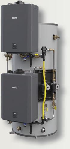
Pre-assembled Electrical Connection

Optimized Performance


A real person’s response to a real person’s question about the effects of glycol in a hydronic heating system.
BY BY CURTIS BENNETT
Well, we hit the jackpot. Ok “we” is a bit of an overstatement, but it has started to work. We have a reader question that came in from my last article asking for readers to submit questions.
As I said before: “I think questions will make the best articles.” It’s hard to write about “random” information hoping you will find it relevant. Getting a question from a reader is ALWAYS relevant.
So once again, I encourage you—yes you—to submit questions so we can write about things that are relevant to you! (write to editor@hpacmag.com)
Ok, first off, I would like to say thank you to the reader, especially for calling me Mr. I do sometimes forget how long I have been in the industry. I usually still think of myself as a newbie.
This reader is an ex-electrician that is getting a little “push” by his heating specialist to add something to the water in his hydronics system. Here is the question:
Good day Mr. Curtis Bennett, In 1999 we built our new house with ICF walls from the foundation on up. As well as concrete floors including the subfloor.
At that time hydronic heating systems were not very popular yet. However, with help I was able to install the hydronic heating system myself. An oil boiler heats the stale water. The system has worked well for me all these years. Now that the government wants everyone to go off oil I am looking at switching to an air-to-water heat pump for the heating only. As you mention, in-floor cooling is not being used here in Canada. I do know that it is very popular in the Netherlands. My heating/cooling specialist wants to change the stale water to glycol. I have read that glycol is not as good a heat conductor as water, and therefore it will take longer to heat up the floor. The reason why my technician wants to change to glycol is that he


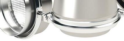
GAS VENT


Flange to Flange ZV-Clamp™ outer connection
Factory installed Double Fail-Safe™ self-sealing FKM gasket connection
Precision factory formed pipe and fittings, with fusion welded seams






claims that it will be better for the lifetime of the pumps. What is your opinion on this? The connection between the indoor and outdoor unit will only have freon. (no water or glycol). Is it advisable to change the water to glycol? Can you give pros and cons please?
First off, good job on installing your system yourself. That takes some guts. It can be very daunting.
Well, who doesn’t like a little physics lesson? Let’s break down what the glycol is there for first. The freezing point of glycol is way lower than that of water. So, we use glycol (antifreeze) as an additive to the water, so we still have fluid but the freezing point is now lower. The freezing point also depends on how much glycol you put in the water.
Why does it matter if the water freezes you ask?
Pipes break when water freezes, and since in a radiant floor the pipes are in the concrete, it’s really hard to fix a burst pipe. Hence the glycol solution.
Ok, let’s get to some math. The heat capacity of fluid is called enthalpy. Enthalpy is the amount of heat that fluid can carry, essentially. The calculation for a Btu is 500 x Delta T x flow (gpm). The key number is 500. That number represents the heat coefficient of the media you are using. In our case this is water.
The heat coefficient of air is only 1. Water has 500 times more capacity to hold heat than air. You know what that means furnace guys? Air is an insulator. (I had to throw that out there.)
The heat coefficient of glycol is lower than water, so when you mix glycol into water the overall heat coefficient goes down. How much it goes down is the question. Now I did use the basic calculation for Btu’s, but in the more complex calculation the temperature of the fluid comes into play as to how much “more” heat can it contain from the temperature it is already at. But we will not get into that today. So how much does the glycol affect the Btus? That’s really the big question

“Yes, it is totally okay to put glycol in radiant floor systems.”
here. Let’s throw in some numbers. Let’s use a 25-degree delta-T and a flow of 10 gallons per minute (gpm). So, with water you get Btu = 500 x 25 x 10 which equals 125,000 Btus.
When we put in 30% glycol, we get 467 x 25 x 10 which equals 116,750 Btus. The difference is not that much. I always find it easier to explain things with real numbers.
The ~467 is the number that changes with glycol, that is your new heat coefficient number. There are some crazy complex calculations to find this number but there are several places that you can track it down.
The long answer to your question is, “Yes, it is totally okay to put glycol in radiant floor systems.” Especially if you are going to be cooling the floor as well. Now you will not put 100% glycol, that’s just crazy, but up to 30% is fine in a house or garage.
As you can see above in the calculation, that 30% mixture will not hinder your ability to move heat around that much and keep your floors warm. Now, the other point that your technician made is also valid.
Glycol in the system is also a lubricant for your pumps. Most pumps today are
wet rotor pumps. The tolerances inside them are very tiny. The smallest bit of rust or buildup and you need a device (hammer) to get the motor spinning again. The glycol helps with this.
One last thing to say about glycol is the viscosity goes up in the heating fluid. So the pumps are working a bit harder to push the same flow rates. This can change the “head pressure” of your system from your original pumping calculations. Just keep that in mind.
On a side note, since you want to also do radiant cooling, you will need some more sophisticated thermostats and feedback to your heat pump controls to watch for dew point. The last thing you want is to wreck your flooring. I have seen it before, and that’s why dew point controls are super important for this specific application.
Thank you again for your question and for calling me “Mr.” It was a very relevant question and one that I am sure many other people wonder about.
(So dear reader, it’s your turn. Send your question to editor@hpacmag.com) <>

Curtis Bennett C.E.T is product development manager with HBX Control Systems in Calgary. He formed the company with Tom Hermann in 2002. HBX control systems are designed, engineered and manufactured in Canada.


Weil-McLain’s Simplicity heat only or combi gas boiler for residential applications delivers up to 95% AFUE with a 10 to 1 turndown and an insulated stainless-steel firetube heat exchanger. The Simplicity is available in 110, 150 and 199 MBH, and the 199 MBH combi can produce 5.3 gpm at a 70F rise. Compact in design (20-in. wide and less than 10-in. deep) it’s suitable for retrofits and tight spaces. weil-mclain.ca


NIBCO has introduced new Webstone Y-pattern thermostatic mixing valves, available in two temperature ranges for water distribution systems and high-temperature hydronic applications, with an optional temperature gauge, or as a body-only G-Series model for a fully custom solution. End connection options include PEX, FIP, MIP, sweat, push, and press, in sizes ranging from ½-in. to 1-in. All products feature lead-free, dezincification-resistant brass and are suitable for plumbing and heating applications. nibco.com

Armstrong Fluid Technology has introduced two new sizes, 40-85 and 60-50, of its Design Envelope Compass R circulators for residential heating, cooling and potable water applications. The Compass R is an energy-efficient variable speed dry-rotor circulator. Designed to replace existing fixed-speed circulators, Compass R can be considered a universal energy upgrade for circulators in its capacity range and installation profile. The circulators can serve applications requiring up to 60 feet of head. armstrongfluidtechnology.com
Conforto provides efficient and high-performing solutions tailored to your energy preferences and heating and cooling needs.
With Conforto, you can expect personalized attention and support across Canada.


Swegon North America has launched two air source heat pump solutions: the Tetris Reversible and the Omicron 4-Pipe Multifunction Heat Recovery. Designed to replace cooling-only chillers, the Tetris Reversible provides heating and cooling, while the Omicron 4-pipe system suits applications requiring both heating and cooling year-round. The systems produce hot water up to 60C/140F and can maintain heating operations down to -20C. The systems are designed for multi-use residential complexes, healthcare facilities, educational institutions and commercial office buildings. swegon.com/na


Enertech Global’s WV is a water–to–water variable-speed geothermal heat pump able to provide in-floor radiant heating, forced air heating and cooling, and 100% of a home’s domestic hot water in one compact unit. With a broad capacity range (0.5 to 5 tons), true dual-fuel compatibility with modulating boiler integration, and no need for a buffer tank, the WV offers space savings for both retrofit and new construction projects. enertechusa.com
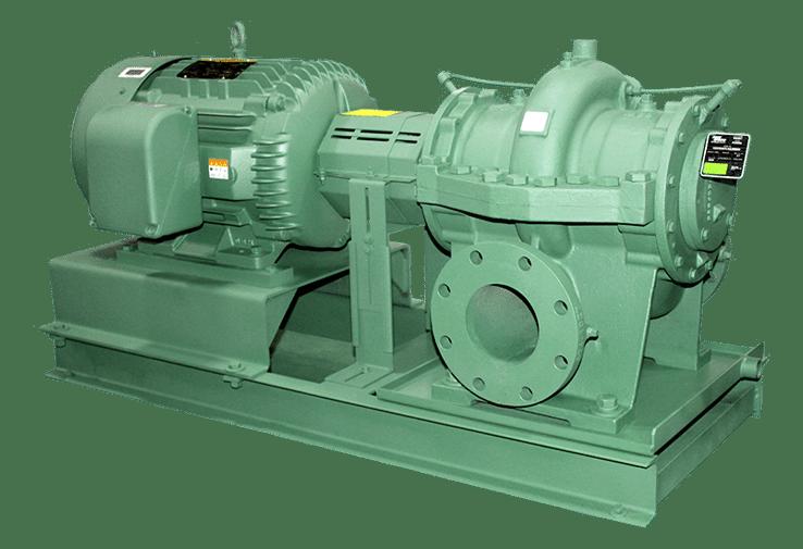
Taco’s HS series horizontal split case pumps are designed to maximize power savings while minimizing operating costs. Suited for commercial and industrial applications, the series features a short shaft design, extending its operational life and reducing maintenance requirements. The pumps are built with a mechanical seal and bearings that are easily accessed without disturbing the top casing. And each pump comes with Taco Tags, a QR code linking to specifications, installation guides, and troubleshooting resources tacoinc.com


Adapting a tried-and-true wood-fired heating system to work with modern technology.
BY JOHN SIEGENTHALER
Ilive in rural upstate NY where there are lots of trees, and many homeowners harvest some of those trees for firewood. They fell them, buck them up into rounds using impressive Stihl or Husqvarna chainsaws, haul the rounds out of the woods in pickups or dump trailers, and use hydraulic splitters to slice them into cordwood. Many get their firewood a year before it’s needed to allow for proper drying.
Some, like me, burn their firewood in a wood stove that’s supplementary to other heat sources. Although we only burn about two face cords each winter, operating our stove on a cold cloudy winter day is something my wife and I enjoy. The warmth from a wood stove is delightful and relaxing.
The stove also stands ready for heating or cooking when utility power is out, which seems to be a more frequent occurrence given our location and the status of local utility lines that were installed during the 1940s.
Some folks in my area “go big” with their approach to wood burning. They opt for whole house heating sourced from an outdoor wood-fired hydronic heater, such as the one my neighbour operates (see Figure 1).
I can’t describe these heat sources as outdoor wood-fired

“boilers,” because they don’t hold their water in a pressurized vessel. Inside an outer shell made of steel roofing, most of these units have a large water-tight welded steel box with a smaller welded steel box, suspended inside. The small box is the combustion chamber. The space between these boxes is filled with water. The fire within the smaller steel box transfers heat through its walls to the water.
Most of these heaters have a circulator that shuttles water through insulated underground piping to some type of distribution system in the house. The illustration in Figure 2 shows the generic internal construction for an outdoor wood-fired hydronic heater.
These heaters are not very efficient. Older models probably land somewhere between 30 to 45% efficient depending on the moisture content of the wood, and how the unit is operated.
I’ve heard accounts of people burning upwards of 30 face cords of wood to keep their home heated using these heaters. Anyone who has ever cut and split that much wood - on a yearly basis - can appreciate how much work that involves.
Still, most of the people I know who own these outdoor woodfired heaters are very devoted to them. They take pleasure in
the fact that they’re not paying for much, if any, fuel oil or propane (natural gas is not available where I live). They’re proud of their independence from foreign fossil fuels. I get it, and I admire their willing -
ness to feed the beast to maintain their autonomy.
But there comes a time when even the best “Paul Bunyan” firewood enthusiasts start “ feeling their age.”
If you’re not sure what that term means, try cutting, splitting, moving and stacking 30 face cords of firewood. You’ll catch on quickly.
Which brings me to a recent inquiry from a fellow who had reached that point in his life. He had installed and operated an outdoor wood-fired heater for years, and he was really attached to it - emotionally, but becoming progressively less attached physically.
He asked me how he could connect an air-to-water heat pump to keep the slabon-grade floor heating system in his 5,000 square-foot shop warm. He wasn’t ready to completely part with the outdoor woodfired heater, but he wanted an option for those days when he chose not to use it.
His shop building had a well-designed floor heating system. Plenty of tubing, conservative circuit lengths, ample underside insulation, and good manifolding. Upon review, it would definitely be adaptable to the heat pump.
The concept I suggested is shown in Figure 3
Let’s start with the wood-only mode. The owner needs to enable the circulator in the outdoor wood-fired heater whenever it is fired. This provides flow through the primary side of a generously-sized brazed plate heat exchanger which separates the open loop of the outdoor wood-fired heater from the remainder of the system, which is designed as closed loop.
The circulator between the heat exchanger and hydraulic separator operates at variable speed to inject heated

Offering market leading efficiency and a 20 year average life span, the Smart 316 Indirect Fired Water Heater provides a solution for every home.


fluid from the secondary side of the heat exchanger into the hydraulic separator.
The injection rate is set by a controller that monitors the supply temperature to the floor circuits, the higher the injection rate, the warmer the supply temperature to the floor circuits.
The target supply temperature is determined based on outdoor reset control. This allows the temperature supplied by the outdoor wood-fired heater to “coast” to the lowest possible value that can still satisfy the heating load of the building.
The distribution circulator runs continuously during the heating season. I like to use continuous circulation in garage and shop buildings that have overhead doors. It helps even out heat delivery across the floor and minimizes the potential for cold spots just inside the overhead doors. The hydraulic separator in this system makes this an easy detail.
The monobloc air-to-water heat pump is connected in parallel with the heat ex-
PORTIONS OF SYSTEM FROM SECONDARY SIDE OF HEAT EXCHANGER TO FLOOR CIRCUITS NEED TO OPERATE WITH ANTIFREEZE SOLUTION
changer. It can operate as the sole heat source, primary heat source, or supplemental heat source. The system controls determine the assigned function of the heat pump.
If the heat pump is intended to be the supplemental heat source, a two-stage room thermostat could be used. The first stage would enable the injection mixing controller. If there’s sufficient heat in the wood-fired heater the thermostat’s second stage would not activate. If the wood-fired heater was off, or too cool to maintain the set indoor temperature, the thermostat’s second stage would enable the heat pump.
Many modern air-to-water heat pumps can monitor a supply temperature sensor, either directly or through an interfacing controller. The variable speed compressor in the heat pump can adjust as necessary to keep the supply water temperature to the floor circuits at some target value based on outdoor reset.
One situation that must be avoided is inadvertently allowing the injection circulator to operate when the heat pump is the sole heat source, and the outdoor woodfired heater is cold. Doing so would shuttle heat sourced from the heat pump through the outdoor heater, needlessly dissipating it to the outside or into the soil surrounding the underground piping. This detail is handled by using the boiler inlet temperature sensor on the injection controller. That sensor is mounted on the primary side of the heat exchanger. If the injection mixing controller is active, it monitors this sensor and slows down or stops the injection circulator when it’s below some set minimum, such as 90F. Thus, if the outdoor heater is cool or cold, and fluid is still circulating through the primary side of the heat exchanger, the injection circulator will remain off, even though there’s a call for space heating.

Tuesday
September 16

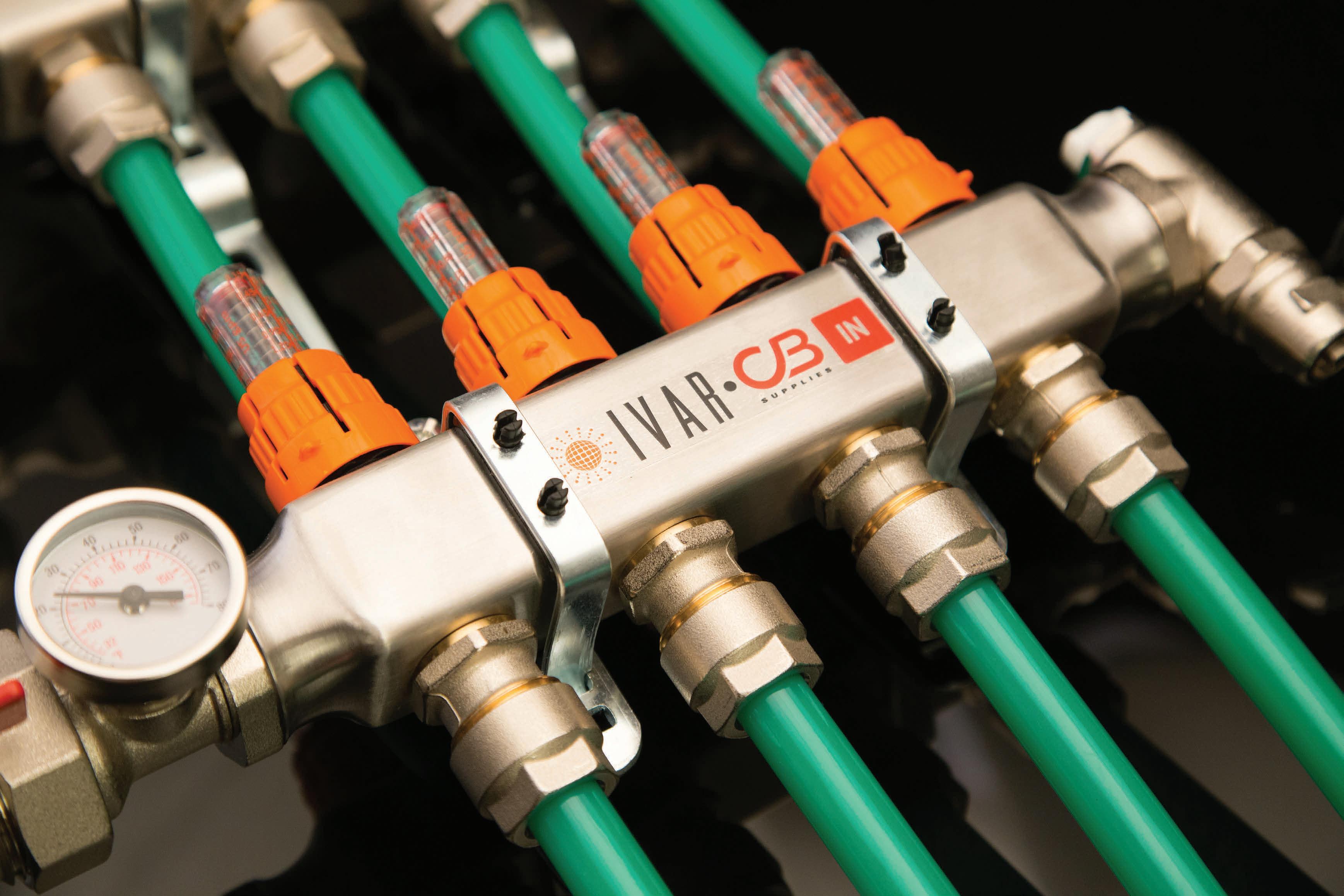
Thanks to our ideal set-up for installers using our unique flow meters on each manifold loop, IVAR stainless-steel manifolds guarantee perfect system balancing, optimizing energy use, while providing premium thermal comfort.
Every manifold set is supplied with all components included in the box, ensuring a smooth commissioning process for radiant system installers.
Pair the IVAR Manifolds with our premium VIPERT™ (PE-RT) Oxygen Barrier Tubing, manufactured specifically for radiant systems, and you have a winning solution every time.
Take advantage of our in-house hydronic expertise, including LoopCAD design and layouts customized for each of your residential and commercial projects.

PORTIONS OF SYSTEM FROM SECONDARY SIDE OF HEAT EXCHANGER TO FLOOR CIRCUITS NEED TO OPERATE WITH ANTIFREEZE SOLUTION
If the injection controller didn’t have this ability, there’s a workaround. Install a differential temperature controller that compares the water temperature entering the primary side of the heat exchanger from the wood-fired heater, to the temperature on the return side of the floor circuits (e.g., entering the lowerright-side connection on the hydraulic separator). If the temperature entering the primary side of the heat exchanger is 5-degrees F or more above the return temperature from the floor circuits, allow the injection mixing controller to operate. If this temperature difference is less than or equal to 3-degrees F, do not allow the injection mixing controller to operate. The closed loop portions of the system would operate with an antifreeze solution. This is necessary to protect the monobloc heat pump from freezing.
Although it may or may not be used, the heat pump has a reversing valve allowing it to operate as a chiller. If the owner wants to add cooling to the shop, it’s just a matter of installing a diverter valve (manual or motorized) that can direct flow from the heat pump to a suitable chilled water air handler. I’ve shown the concept in Figure 4
Any piping carrying chilled fluid must be insulated and vapour sealed. Also note that the diverter valve, in this case a three-way manually operated ball valve, is only used on the pipe carrying fluid out of the heat pump. The other pipe leads back to the system to provide “communication” with the expansion tank.
The heat pump controls would be set for a desired leaving chilled water temperature, typically 45 to 50F (7 to 10C).
The compressor speed modulates as necessary to maintain that setpoint temperature.
This application demonstrates that what might be perceived as “low tech” heating (e.g., burning wood in an outdoor heater) can be combined with a state-of-the-art heat pump using off-the-shelf hardware to keep a shop comfortable though the winter, and maybe even through the summer. <>

John Siegenthaler, P.E., has over 40 years of experience designing modern hydronic heating systems and is the author of Modern Hydronic Heating (4th edition) and Heating with Renewable Energy (visit hydronicpros.com).
The Total Hydronic Heat Pump Solution for heating, cooling, and domestic hot water

Residential Air-to-Water Heat Pump System featuring an outdoor unit, an indoor unit and a steel buffer tank (20 gal). Pairs with Vitocell 100-V 53, 66 and 79 gallon indirect tanks. 3 sizes available: 20 to 51 MBH for cooling / 28 to 78 MBH for heating.


From boilers to pumps, radiant to tanks—find what you need, check stock, and order anytime at master.ca. Trusted brands. Real-time inventory. Backed by our national support.