SHUTTLE VALVE CATALOG

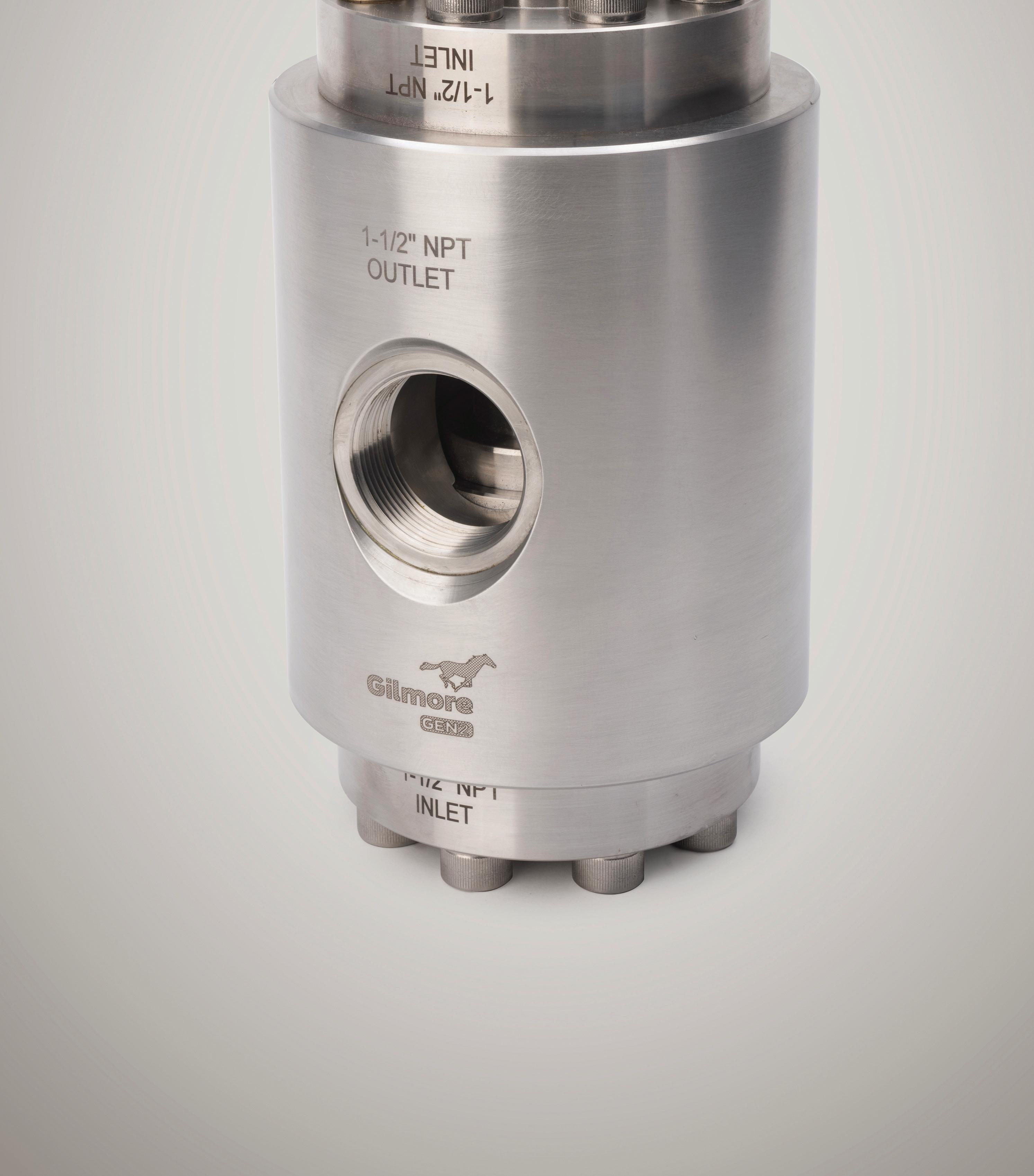
Gilmore is the technology leader in Hydraulic Shuttle Valves. Our patented shuttle valves combine into three major product families.

Gilmore manufactures a variety of different shuttle types to meet the most rigorous requirements. We offer different features, connections, working pressures, flow capacities and sealing geometry to fit your project requirements. Below are the three major product families of shuttles and their variations, Please reach out to us if you do not see an option fitting your application.
GEN2 Disc Shuttle I Stackable I Biased
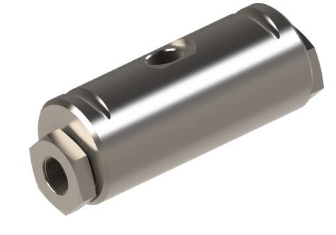
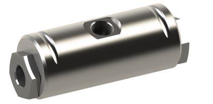
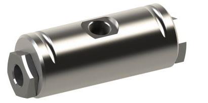
The GEN2 disc shuttle is our reliable low flow shuttle valve. This style is compact, resilient soft seal valves that are perfectly suited for providing redundancy in pilot circuits and actuation of larger components. The patented disc seal geometry has been extensively cycle tested at full MAWP (5000 psi) with 8 GPM flow.
Mark IV Shuttle I Inline I Stackable I Biased
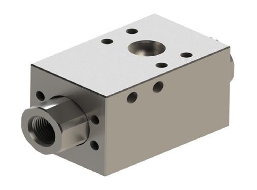
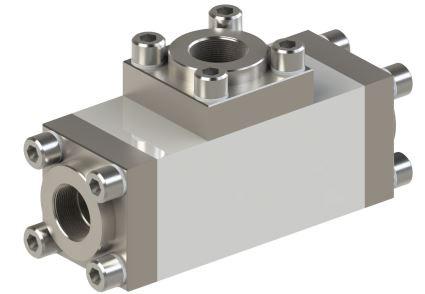
The new standard of reliability. The Mark IV Shuttle Valve improves upon the Mark III, adding better performance and modularity. The increase in cycle life of the valve was proven through extreme testing to meet the demand of 5 year service life under normal operating conditions. Use this valve for new build equipment where you want to have the best performing, most easily serviceable shuttle valve in the market.
GEN2 V-Seal Shuttle I Inline
The Traditional GEN2 Shuttle Valve design exceeds new offshore industry requirements while keeping the traditional Gilmore shuttle valve footprint. The increase in cycle life of the valve was proven through extreme testing to meet the demand of 5 year service life under normal operating conditions. Use this valve to upgrade the legacy traditional shuttle valves in your existing equipment as they have the same footprint and do not require re-piping .
Table of ContentsShuttle Valve
DRILLING | PRODUCTION | INDUSTRIAL INFO@Gilmore.com www.gilmore.com SHUTTLE -042120-001-02
Shuttles are used as a means to provide redundancy actuation for a critical function. They allow multiple pressure sources to actuate a function when the primary function loses pressure.
1. Cushioned - also known as hydraulic damping, occurs when the shuttle shifts into a tight clearance cavity between the adapter and the shuttle collar. This serves to slow down the shuttle and reduce shock and wear.

2. Interflow - low or high interflow options deal with how much fluid communi cates between the two inlets as the shuttle shifts from one position to another.
3. HD (Hi Drag) - This feature is an o-ring placed in the shuttle with a higher than standard squeeze. It is used to reduce rapid oscillation that can lead to prema ture failure and helps maintain last position logic.
4. Shuttle - As the only moving component, the shuttle shifts back and forth to allow fluid to pass from a given inlet to the outlet, while blocking the opposite inlet.
5. Metal to Metal Seat - a resilient seat that is far more debris tolerant than elastomeric or soft seat shuttles.
6. Pressure Biased Adapter - used for ROV intervention.
7. Stackable Shuttles - available for Mark IV valves. These designs eliminate excess piping, reduce footprint, simplify connections and decrease leak paths. (See figure 2)
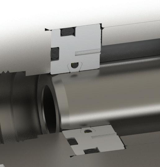
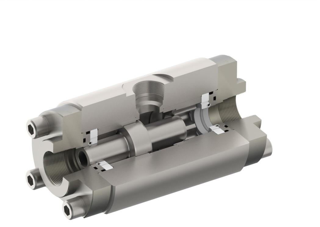

8. V-Seal - A patented technology that utilizes an elastomer and polymer (PTFE) combination that fully engages the o-ring groove, eliminating feathering and extrusion. (See figure 3)

1. 3. 5. 4. 2. 6. 7. Reference SheetShuttle Valve
Figure
1
Mark IV
Shuttle
Figure
2
Mark IV Shuttle with Pressure Biased Attachment
Figure 3 GEN2 Shuttle 8. OUTLET INLET 2 INLET 1 INLET 2 INLET 1 OUTLET OUTLET INLET 1 INLET 2 INLET 3 INLET 4 SHUTTLE -042120-001-03 DRILLING | PRODUCTION | INDUSTRIAL
Available Configurations:
1/4” and 3/8” low interflow, SAE, and NPT configurations with customizable end connections and mounting.
FUNCTIONAL DESIGN SPECIFICATION
Maximum Allowable Working Pressure 5000 psi
Minimum Recommended Working Pressure 1500 psi
Recommended Maximum Operating Flow 8 GPM
Acceptable Leakage Rate
DRILLING
PSI,
or
drops per minute
GPM Flow Coefficient (Cv)
Minimum Shift Flow (Horizontal)
Cracking Pressure
psi
Hydrostatic Proof Pressure 7500 psi
Predicted Cycle Life 2500 cycles
Operating Temperature Range
Storage Temperature Range
Acceptable Operating Fluid Types
to 150˚F
to 150˚F
Water or mineral oil-based control fluid
Mounting Restrictions None
US Patent 10,133,282
Maximum Operating Depth 12,000 ft
BILL OF MATERIALS

Item Number Description Material
1 BODY
END CAP
CAGE-LI
A276 TP 316
A276 UNS S21800 (Nitronic 60)
A276 TP S21800 (Nitronic 60)
SEAL DISC PEEK
O-RING HNBR
SHUTTLE
A276 UNS S21800 (Nitronic 60)
Part Numbers*
Valve, Shuttle 1/4”
Low Interflow, Disc Seat
Valve, Shuttle 1/4” SAE, Low Interflow, Disc Seat
Shuttle, 3/8”
Shuttle,
Low Interflow, Disc Seat
Low Interflow, Disc Seat
Technical Sheet Disc Seal 1/4”
3/8” 5000
Low Interflow
0
.1
.6
<10
32˚F
32˚F
2
3
4
5
6
Description 29005
NPT,
29006
29007 Valve,
NPT,
29008 Valve,
3/8” SAE,
GEN2 Disc Shuttle Valve INLET 2 OUTLET INLET 1
| PRODUCTION | INDUSTRIAL INFO@Gilmore.com www.gilmore.com SHUTTLE -042120-001-04 *The repair kit part number will match the category part numbers with (-RK) at the end. *The seal kit part number will match the category part numbers with (-SK) at the end.
Available Configurations:
1/4” and 3/8” high interflow, SAE, and NPT configurations with customizable end connections and mounting.

FUNCTIONAL DESIGN SPECIFICATION
Maximum Allowable Working Pressure 5000 psi
Minimum Recommended Working Pressure 1500 psi
Recommended Maximum Operating Flow 8 GPM
Acceptable Leakage Rate
DRILLING
Disc Seal 1/4” or 3/8” 5000 PSI, High Interflow
drops per minute
GPM Flow Coefficient (Cv)
Minimum Shift Flow (Horizontal)
Cracking Pressure
psi
Hydrostatic Proof Pressure 7500 psi
Predicted Cycle Life 2500 cycles
Operating Temperature Range
Storage Temperature Range
Acceptable Operating Fluid Types
Mounting Restrictions
to 150˚F
to 150˚F
Water or mineral oil-based control fluid
None
US Patent 10,133,282
Maximum Operating Depth 12,000 ft
BILL OF MATERIALS

Item Number Description Material
1 BODY A276 TP 316
END CAP
CAGE-HI
A276 UNS S21800 (Nitronic 60)
A276 TP S21800 (Nitronic 60)
SEAL DISC PEEK
O-RING HNBR
SHUTTLE
A276 UNS S21800 (Nitronic 60)
Part Numbers* Description
- 2 Valve, Shuttle 1/4”
High Interflow, Disc Seat
- 2 Valve, Shuttle 1/4” SAE, High Interflow, Disc Seat
- 2 Valve, Shuttle 3/8” NPT, High Interflow, Disc Seat
- 2 Valve, Shuttle 3/8” SAE, High Interflow, Disc Seat
repair kit part
seal kit part number
category part
category part
GEN2 Disc Shuttle Valve
Technical Sheet
0
.1
.6
<20
32˚F
32˚F
2
3
4
5
6
29005
NPT,
29006
29007
29008
OUTLET INLET 2 INLET 1 SHUTTLE -042120-001-05
| PRODUCTION | INDUSTRIAL *The
number will match the
numbers with (-RK) at the end. *The
will match the
numbers with (-SK) at the end.
Available Configurations:
1/4” and 3/8” low interflow, SAE, and NPT configurations with customizable end connections and mounting.
FUNCTIONAL DESIGN SPECIFICATION
Maximum Allowable Working Pressure 5000 psi
Minimum Recommended Working Pressure 1500 psi
Recommended Maximum Operating Flow 4 GPM
Acceptable Leakage Rate
Minimum Shift Flow (Horizontal)
Flow Coefficient (Cv)
Cracking Pressure
Hydrostatic Proof Pressure
drops per minute
GPM
<20 psi
PSI,
or
Biased,
Interflow

psi
Predicted Cycle Life 2500 cycles
Operating Temperature Range
Storage Temperature Range
Acceptable Operating Fluid Types
Mounting Restrictions
to 150˚F
to 150˚F
Water or mineral oil-based control fluid
US Patent 10,133,282
Maximum Operating Depth 12,000 ft
BILL OF MATERIALS
Item Number Description Material
1 BODY
A276 TP 316
END CAP A276 UNS S21800 (Nitronic 60)
CAGE-LI
A276 TP S21800 (Nitronic 60)
SEAL DISC PEEK
O-RING HNBR
SHUTTLE
A276 UNS S21800 (Nitronic 60)
SPRING ELGILOY
Part Numbers* Description
- 1 Valve, Shuttle 1/4”
Low Interflow, Disc Seat, Spring Biased
- 1 Valve, Shuttle 1/4” SAE, Low Interflow, Disc Seat, Spring Biased
1 Valve, Shuttle 3/8” NPT, Low Interflow, Disc Seat, Spring Biased
- 1 Valve, Shuttle 3/8” SAE, Low Interflow, Disc Seat, Spring Biased
DRILLING
*The repair kit part number
with (-RK)
seal kit part number
category part
category
GEN2 Disc Shuttle Valve Technical Sheet Disc Seal 1/4”
3/8” 5000
Spring
Low
0
.1
.6
7500
32˚F
32˚F
None
2
3
4
5
6
7
29005
NPT,
29006
29007-
29008
OUTLET INLET 2 INLET 1 SHUTTLE -042120-001-06
| PRODUCTION | INDUSTRIAL
will match the
numbers
at the end. *The
will match the
part numbers with (-SK) at the end.
Available Configurations:
1/4” and 3/8” high interflow, SAE, and NPT configurations with customizable end connections and mounting.

FUNCTIONAL DESIGN SPECIFICATION
Maximum Allowable Working Pressure 5000 psi
Minimum Recommended Working Pressure 1500 psi
Recommended Maximum Operating Flow 4 GPM
Acceptable Leakage Rate 0 drops per minute
Seal
or
PSI, Spring Biased, High Interflow
Minimum Shift Flow (Horizontal)
GPM Flow Coefficient (Cv)
Cracking Pressure
psi
Hydrostatic Proof Pressure 7500 psi
Predicted Cycle Life 2500 cycles
Operating Temperature Range
Storage Temperature Range
Acceptable Operating Fluid Types
to 150˚F
to 150˚F
Water or mineral oil-based control fluid
Mounting Restrictions None
US Patent 10,133,282
Maximum Operating Depth 12,000 ft
BILL OF MATERIALS

Item Number Description Material
BODY A276 TP 316
END CAP A276 UNS S21800 (Nitronic 60)
CAGE-HI
A276 TP S21800 (Nitronic 60)
SEAL DISC PEEK
O-RING HNBR
SHUTTLE
A276 UNS S21800 (Nitronic 60)
SPRING ELGILOY
Part Numbers* Description
29005 - 3 Valve, Shuttle 1/4” NPT, Spring Biased, High Interflow, Disc
- 3 Valve, Shuttle 1/4” SAE, Spring Biased, High Interflow, Disc
- 3 Valve, Shuttle 3/8” NPT, Spring Biased, High Interflow, Disc
- 3 Valve, Shuttle, 3/8” SAE, Spring Biased, High Interflow, Disc
*The repair kit part number
with (-RK)
category part
the
seal kit part number
with (-SK)
match
category part
GEN2 Disc Shuttle Valve Technical Sheet Disc
1/4”
3/8” 5000
.1
.6
<20
32˚F
32˚F
1
2
3
4
5
6
7
29006
29007
29008
INLET 1INLET 2 OUTLET SHUTTLE -042120-001-07 DRILLING | PRODUCTION | INDUSTRIAL
will match the
numbers
at
end. *The
will
the
numbers
at the end.
Mark
SINGLE
2 INLET 1 OUTLET
INLET 3
1
Available Configurations: 1/2”, 1”, and 1-1/2” in low interflow or high interflow, SAE and NPT configurations with customizable end connections and mounting.
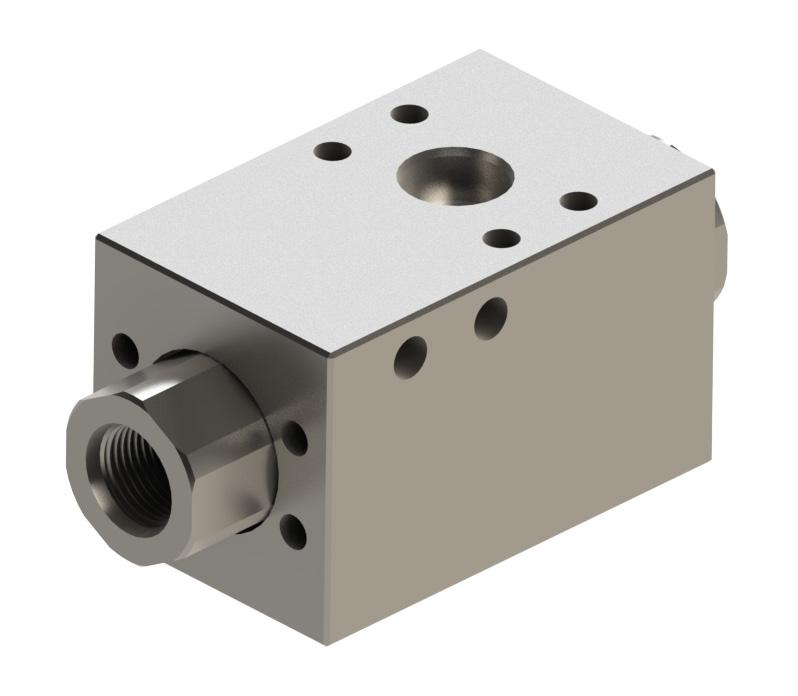
2
FUNCTIONAL DESIGN SPECIFICATION
Maximum Allowable Working Pressure 5000 psi
Minimum Recommended Working Pressure 1500 psi
Recommended Maximum Operating Flow 45 GPM
Acceptable Leakage Rate
Minimum Shift Flow (Horizontal)
4 drops per minute
0.75 GPM
Minimum Shift Flow (Vertical) 2.0 GPM Flow Coefficient (Cv) 1.1
Recommended Full Shift Pressure 1500 psi
Hydrostatic Proof Pressure 7500 psi
Predicted Cycle Life 2500 Cycles
Operating Temperature Range
Storage Temperature Range
Acceptable Operating Fluid Types
Mounting Restrictions
1/2”, 5000 PSI, Non-Biased Low and High Interflow
32˚F to 150˚F
32˚F to 150˚F
Water or mineral oil-based control fluid
None
US Patent 9,915,275
Maximum Operating Depth 15,000 ft
BILL OF MATERIALS

Item Number* Description Material
1 BODY
A276 TP 316 (316 SS)
SHUTTLE, MKIV A276 UNS S21800 (Nitronic 60)
INSERT, THREADED A276 S21800 (Nitronic 60)
ADAPTER, SHUTTLE A276 TP S21800 (Nitronic 60)
ADAPTER, OUTLET A276 TP 316L (316 SS)
SEAL SUB A276 TP 316L (316 SS)
SHCS 5/16 - 18 UNC A453 GR 660
O-RING (ITEM* 8 - 11) BUNA N
Part Numbers** Description
Valve, Shuttle, MKIV, 1/2” Inline, SAE, Low Interflow, HD 29026 Valve, Shuttle, MKIV, 1/2” Stack, C62, Low Interflow, HD 29055 Valve, Shuttle, MKIV, 1/2” Inline, NPT, High Interflow, HD
kit
INLET
Technical Sheet
29025
2
3
4
5
6
7
8
STACKABLE OUTLET INLET
IV Shuttle Valve INLET
SHUTTLE -042120-001-08 DRILLING | PRODUCTION | INDUSTRIAL **The repair kit part number will match the category part numbers with (-RK) at the end. **The seal
part number will match the category part numbers with (-SK) at the end.
5000 PSI, Pressure Biased
FUNCTIONAL DESIGN SPECIFICATION
Maximum Allowable Working Pressure 5000 psi
Minimum Recommended Working Pressure 1500 psi
Recommended Maximum Operating Flow
Acceptable Leakage Rate
SINGLE
GPM (Inlet 1) 40 GPM (Inlet 2)
drops per minute
Minimum Shift Flow (Non-Biased Inlets) 0.75 GPM
Minimum Shift Pressure (Biased Inlets) 200 psi Flow Coefficient (Cv) (Inlet 1 and 2)
(Inlet 1) 1.0 (Inlet 2)
Recommended Full Shift Pressure 1500 psi
Hydrostatic Proof Pressure 7500 psi
Predicted Cycle Life 2500 Cycles
Operating Temperature Range
Storage Temperature Range
Acceptable Operating Fluid Types
Mounting Restrictions
32˚F to 150˚F
to 150˚F
Water or mineral oil-based drilling control fluid
None
US Patent 9,915,275
Maximum Operating Depth 15,000 ft
BILL OF MATERIALS

Number*
BODY
SHUTTLE
Configurations:
1”, and 1-1/2” in low interflow or high interflow
with
and
Material
A276 TP 316
A276 UNS S21800 (Nitronic 60)
INSERT, THREADED A276 TP S21800 (Nitronic 60)
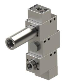
SHUTTLE A276 TP 316 (316 SS)
SEAL, SUB A276 TP 316 (316 SS)
SHCS 5/16 – 18 UNC A453 GR 660
ADAPTER, OUTLET A276 TP 316 (316 SS)
COMPRESSION
N07500 (X-750)
ROD B637 N07718 (INCONEL 718)
A276 UNS S21800 (Nitronic 60)
AF
O-RING (ITEM* 12 - 15) BUNA N
Technical Sheet 1/2”,
45
4
1.1
32˚F
Continued on page 9.1 STACKABLE
OUTLET INLET 2 INLET 1 OUTLET INLET 3 Mark IV Shuttle Valve INLET 2 INLET 1
Item
Description
1
2
3
4 ADAPTER,
5
6
7
8 SPRING,
UNS
9 SPRING
10 PISTON
11 WEARBAND DELRIN
12
Available
1/2”,
configurations
customizable end connections
mounting. SHUTTLE -042120-001-09 DRILLING | PRODUCTION | INDUSTRIAL
SINGLE
OUTLET
1 OUTLET
3
1
Configurations:
1”, and 1-1/2” in low interflow or high interflow configurations with customizable end connections and mounting.


Part Numbers** Description
Valve, Shuttle, In-Line, MKIV, 2 Inlets, 1/2” SAE IN, 3/4” SAE IN, 1/2” SAE Out, 5000 psi, Pressure Biased, 200 psi Shift
1/2”, 5000 PSI, Pressure Biased
of Inlets
Valve, Shuttle, MKIV, 1/2” Stack, SAE, Pressure Biased, LI HD, 3 Inlets, 200 psi Shift
Valve, Shuttle, MKIV, 1/2” Stack, SAE, 2X Pressure Biased, LI HD, 4 Inlets, 200 PSI Shift 4
Valve, Shuttle, MKIV, 1/2” Stack, SAE, Pressure Biased, LI HD, 4 Inlets, 200 psi Shift 4
Valve, Shuttle, MKIV, 1/2” Inline, C62, Pressure biased, 200 psi Shift 2 29099 Valve, Shuttle, In-Line, MKIV, 2 Inlets, 1/2” SAE IN, 3/4” SAE IN, 1/2” SAE Out, 5000 psi, Pressure Biased, 350 psi Shift***
Mark IV Shuttle Valve Technical Sheet
(Cont.)
Number
29027
2 29028
3 29029
29038
29056
2
STACKABLE
INLET
INLET
INLET
INLET 2 INLET 2 Available
1/2”,
***Part Number 29099 - Pressure Biased, 350 psi Shift SHUTTLE -042120-001-09.1 DRILLING | PRODUCTION | INDUSTRIAL **The repair kit part number will match the category part numbers with (-RK) at the end. **The seal kit part number will match the category part numbers with (-SK) at the end.
INLET 2
Available Configurations: 1/2”, 1”, and 1-1/4” in SAE configurations with customizable end connections and mounting.
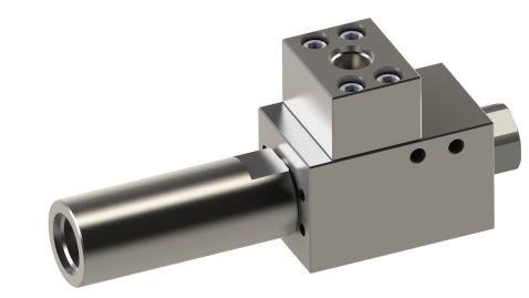
1
FUNCTIONAL DESIGN SPECIFICATION
Maximum Allowable Working Pressure 5000 psi
Minimum Recommended Working Pressure 1500 psi
Recommended Maximum Operating Flow (Inlet 1 and 2)
Acceptable Leakage Rate
Minimum Shift Flow (Horizontal)
GPM
4 drops per minute
GPM
Flow Coefficient (Cv) (Inlet 1 and 2) 1.1
Recommended Full Shift Pressure 1500 psi
Hydrostatic Proof Pressure 7500 psi
Predicted Cycle Life 2500 Cycles
Operating Temperature Range
Storage Temperature Range
Acceptable Operating Fluid Types
Mounting Restrictions
DRILLING
Biased
32˚F to 150˚F
32˚F to 150˚F
Water or mineral oil-based control fluid
None
US Patent 9,915,275
Maximum Operating Depth 15,000 ft
BILL OF MATERIALS

Item Number* Description Material
1 BODY
INSERT, THREADED
A276 TP 316 (316 SS)
A276 S21800 (Nitronic 60)
ADAPTER A276 TP S21800 (Nitronic 60)
SPRING COMPRESSION INCONEL (X-750)
ADAPTER, OUTLET
A276 TP 316L (316L SS)
SEAL, SUB A276 TP 316L (316L SS)
SHCS 5/16 - 18 UNC A453 GR 660
SHUTTLE, SPRING BIASED
GUIDE NUT
A276 TP S21800 (NITRONIC 60)
ASTM B169 C61400 (ALUM BRONZE)
O-RING (ITEM* 10 - 12) BUNA N
Part Numbers** Description
Valve, Shuttle, MKIV, 1/2” Inline, SAE, Spring Biased
repair kit part
with
seal kit part number
category part
category
Technical Sheet 1/2”, 5000 PSI Spring
45
2.5
2
3
4
5
6
7
8
9
10
Mark IV Shuttle Valve
29053
OUTLET
INLET
SHUTTLE -042120-001-10
| PRODUCTION | INDUSTRIAL **The
number will match the
numbers
(-RK) at the end. **The
will match the
part numbers with (-SK) at the end.
Available
1”, and 1-1/2” in low interflow or high interflow configurations with customizable end connections and mounting.
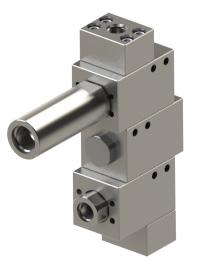
FUNCTIONAL DESIGN SPECIFICATION
Maximum Allowable Working Pressure 6000 psi
Minimum Recommended Working Pressure 1500 psi
Pressure Biased (Inlet 1) Maximum Recommended Operating Flow 175 GPM
Spring Biased (Inlet 2) Maximum Recommended Operating Flow 150 GPM
Acceptable Leakage Rate 4 drops per minute
Pressure Biased Inlet Flow Coefficient (Cv) (Inlet 4)
Non-Biased Inlet Flow Coefficient (Cv) (Inlet 1)
Pressure Biased Full Shift Pressure 400 psi
Pressure Biased Inlet Cracking Pressure 200 psi
Hydrostatic Proof Pressure 9,000 psi
Predicted Cycle Life 2500 Cycles
Predicted Cycle Life Biased Adapters 1000 Cycles Operating Temperature Range
32˚F to 150˚F Storage Temperature Range
Acceptable Operating Fluid Types
32˚F to 150˚F
Water or mineral oil-based drilling control fluid
None US Patent 9,915,275
Mounting Restrictions
Maximum Operating Depth 15,000 ft
BILL OF MATERIALS

BODY
A276 TP 316 (316 SS)
1” CODE
A276 UNS S21800 (Nitronic 60)
A276 UNS S21800 (Nitronic 60)
THREADED A276 UNS S21800 (Nitronic 60)
7/16-14
A286 (GR660)
A276 TP 316 (316 SS)
A276 UNS S21800 (Nitronic 60)
PSI SHIFT INCONEL (X-750)
INLET 2 Mark IV Shuttle Valve Technical Sheet 1”, 6000 PSI, Stackable Pressure Biased
4.7
5.4
OUTLET OUTLET INLET 1 INLET 2 INLET 3 INLET 1
Item Number* Description Material 1
2 ADAPTER,
62
3 SHUTTLE
4 INSERT,
5 SHCS,
UNC
6 ADAPTER, SEAL SUB
7 ADAPTER, PBS
8 SPRING COMPRESSION, 200
OUTLET INLET 5 INLET 3 INLET 1 INLET 4 INLET 2
Configurations: 1/2”,
Continued on page 11.1 SHUTTLE -042120-001-11 DRILLING | PRODUCTION | INDUSTRIAL
3
OUTLET
BILL OF MATERIALS (CONT.)

SPRING ROD
PISTON, PRESSURE BIASED
SHUTTLE, PRESSURE BIASED
B637 ALLOY NO7718
A276 UNS S21800 (Nitronic 60)
A276 UNS S21800 (Nitronic 60)
WEARBAND PRESSURE BIASED DELRIN AF
INSERT, SEAL SUB
A276 TP 316 (316 SS)
O-RING (ITEM* 14 - 19) HNBR
INLET
OUTLET
Part Numbers** Description Number of Inlets
1
2
Available Configurations:
1”, and 1-1/2” in low interflow or high interflow configurations with customizable end connections and mounting.

DRILLING
29015
Valve, Shuttle, MKIV, 1” SAE, Inline, Pressure Biased, 400 psi, 5000 psi 2 29019
Valve, Shuttle, MKIV, 1” C62, W/Seal Sub, LI, HD, Pressure Biased, 4 Inlets, 6000 psi 4 29031
Valve, Shuttle, MKIV, 1” C62 W/ Seal Sub, LI, HD, Pressure Biased, 200 psi shift, 3 Inlets, 6000 psi 3 29033
Valve, Shuttle, MKIV, 1” C62, LI, HD, Pressure Biased, 200 psi Shift, 4 Inlets, 6000 psi 4 29034
Valve, Shuttle, MKIV, 1” C62, LI, HD, 2X Pressure Biased, 200 psi Shift, 4 Inlets, 6000 psi 4 29035
Valve, Shuttle, MKIV, 1” C62, LI, HD, Pressure Biased, 200 psi Shift, 5 Inlets, 6000 psi 5
Valve, Shuttle, MKIV, 1” C62, LI, HD, Pressure Biased, 200 psi Shift, 6 Inlets, 6000 psi 6
Valve, Shuttle, MKIV, 1” C62, LI, HD, Pressure Biased, 200 psi Shift, 7 inlets, 6000 psi 7
*The repair kit part number will match the category part numbers with (-RK)
the
*The seal kit part number will match the category part numbers with (-SK)
the
INLET 2 Mark IV Shuttle Valve Technical Sheet 1”, 5000 PSI, Stackable Pressure Biased (Cont.)
29039
29040
1 OUTLET INLET 2 INLET 3 INLET 4 INLET 5 INLET 1
Item Number* Description Material 9
10
11
12
13
14
INLET
INLET
INLET
1/2”,
SHUTTLE -042120-001-12
| PRODUCTION | INDUSTRIAL
at
end.
at
end.
Available Configurations: 1/2”, 1”, and 1-1/4” in SAE configurations with customizable end connections and mounting.
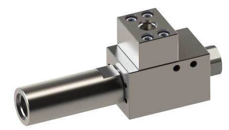
FUNCTIONAL DESIGN SPECIFICATION
Maximum Allowable Working Pressure 5000 psi
Minimum Recommended Working Pressure 1500 psi
Spring Biased inlet Maximum Recommended Operating Flow 175 GPM
Pressure Biased 150 GPM
Acceptable Leakage Rate 4 drops per minute
Spring Biased Inlet Flow Coefficient (Cv)
Non-Biased Inlet Flow Coeffiecient (Cv)
5.4 Pressure Biased Inlet
Spring Biased Inlet Shift Pressure 200 psi
Spring Biased Full Shift Flow @ 1,500 psi 7.5 GPM
Hydrostatic Proof Pressure 7500 psi
Predicted Cycle Life 1000 Cycles
Operating Temperature Range 32˚F to 150˚F
Storage Temperature Range 32˚F to 150˚F
Acceptable Operating Fluid Types
Mounting Restrictions
Water or mineral oil-based control fluid
None
US Patent 9,915,275
Maximum Operating Depth 15,000 ft
BILL OF MATERIALS

A276 TP 316 (316 SS)
THREADED A276 UNS S21800 (Nitronic 60)
OUTLET A276 TP 316L (316L SS)
7/16-14 UNC A286 GR660
A276 UNS S21800 (Nitronic 60)
(X-750)
C61499
UNS S21800
A276 TP 316L (316
Technical Sheet 1”, 5000 PSI Pressure Biased and Spring Biased
5.4
4.7
Item Number* Description Material 1 BODY
2 INSERT,
3 ADAPTER
4 SHCS,
5 ADAPTER, PBS
6 SPRING COMPRESSION, 200 PSI SHIFT INCONEL
7 NUT GUIDE B169
8 SHUTTLE A276
9 INSERT, SEAL SUB
SS) 10 O-RING (ITEM* 10 - 11) BUNA N Mark IV Shuttle Valve OUTLET INLET 2 INLET 1 OUTLET INLET 2 INLET 1 Continued on page 13.1 SHUTTLE -042120-001-13 DRILLING | PRODUCTION | INDUSTRIAL
Part
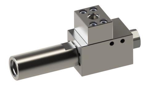

Technical Sheet 1”, 5000 PSI Pressure Biased and Spring Biased (Cont.) Available Configurations: 1/2”, 1”, and 1-1/4” in SAE configurations with customizable end connections and mounting. Mark IV Shuttle Valve
Numbers** Description 29016 Valve, Shuttle, MKIV, 1” Inline, SAE, Spring Biased 5000 psi 29020 Valve, Shuttle, MKIV, 1” Inline, SAE, Pressure Biased 5000 psi, 200 psi Shift, 1-1/4” SAE OUTLET INLET 2 INLET 1 OUTLET INLET 2 INLET 1 SHUTTLE -042120-001-13.1 DRILLING | PRODUCTION | INDUSTRIAL **The repair kit part number will match the category part numbers with (-RK) at the end. **The seal kit part number will match the category part numbers with (-SK) at the end.
Mark
Shuttle Valve Technical Sheet
6000 PSI, Non-Biased, Low/High Interflow and Stacked
FUNCTIONAL DESIGN SPECIFICATION
Maximum Allowable Working Pressure 6000 psi
Minimum Recommended Working Pressure 1500 psi
Spring Biased Inlet Maximum
Recommended Operating Flow 175 GPM
Acceptable Leakage Rate 4 drops per minute
Minimum Shift Flow (Horizontal)
Flow Coefficient (Cv) (Inlet 1 and 2) 5.4
GPM
Recommended Full Shift 1500 psi
Hydrostatic Proof Pressure 9000 psi
Predicted Cycle Life 2500 Cycles
1
Operating Temperature Range
32˚F to 150˚F
Storage Temperature Range 32˚F to 150˚F
Acceptable Operating Fluid Types
Water or mineral oil-based drilling control fluid
Mounting Restrictions None
US Patent 9,915,275
Maximum Operating Depth 15,000 ft
BILL OF MATERIALS

Item Number* Description Material
Available Configurations: 1”, and 1-1/2” in low interflow or high interflow configurations with customiz able end connections and mounting.

1 BODY A276 TP 316 (316 SS)
SHUTTLE, LI, HD A276 UNS S21800 (Nitronic 60)
INSERT, THREADED A276 S21800 (Nitronic 60)
ADAPTER, 1” A276 S21800 (Nitronic 60)
O-RING (ITEM* 5 - 7) BUNA N
Part
29012
Description
Shuttle, MKIV,
psi, Inline, LI, HD
C62, Seal Sub,
of Inlets
DRILLING
repair kit
with (-RK)
with (-SK)
Valve, Shuttle, MKIV,
C62 Seal Sub, 6000 psi,
Valve, Shuttle, MKIV,
Inlets,
C62, LI, HD,
**The seal kit part number
match the category part
2.5
IV
1”,
2
3
4
5
INLET 2 INLET
SINGLE
Numbers**
Number
Valve,
1”
6000
2 29014
1”
90°, LI, HD 2 29032
1”
3
6000 psi 3 OUTLET STACKABLE INLET 2 INLET 1 INLET 3 OUTLET
SHUTTLE -042120-001-14
| PRODUCTION | INDUSTRIAL **The
part number will match the category part numbers
at the end.
will
numbers
at the end.
OUTLET
INLET 2 INLET 1
FUNCTIONAL DESIGN SPECIFICATION
Maximum Allowable Working Pressure 6000 psi
Minimum Recommended Working Pressure 500 psi
Maximum Operating Flow
275 GPM
Minimum Shift Flow (Low Interflow) 5 GPM
Minimum Shift Flow (High Interflow) 10 GPM
Acceptable Leakage Rate
Flow Coefficient (Cv) (Inlet 1 and Inlet 2) 12
1/2”,
PSI, Single Stack
Available Configurations:
1”, and 1-1/2” in low interflow or high interflow configurations with customiz able end connections and mounting.
drops per minute
Hydrostatic Proof Pressure 9000 psi
Predicted Cycle Life 2500 Cycles
Operating Temperature Range
Storage Temperature Range
Acceptable Operating Fluid Types
32˚F to 150˚F
32˚F to 150˚F
Water or mineral oil-based control fluid
Mounting Restrictions None
US Patent 9,915,275
BILL OF MATERIALS

Item Number* Description Material
1 BODY
INSERT, THREADED 1-1/2”
3 SHUTTLE
A276 TP 316 (316 SS)
A276 UNS S21800 (Nitronic 60)
A276 UNS S21800 (Nitronic 60)
4 ADAPTER, 1” CODE 62 A276 UNS S21800 (Nitronic 60)
5 O-RING (ITEM* 5 - 7) HNBR
Part Numbers** Description
29059 Valve, Shuttle, MKIV, 1-1/2” C62, Inline, Low Interflow, HD
29060 Valve, Shuttle, MKIV, 1-1/2” C62, 90°, High Interflow, HD

**The repair kit part number will match the category part numbers with (-RK) at the end.
**The seal kit part number will match the category part numbers with (-SK) at the end.
Mark IV Shuttle Valve Technical Sheet 1
6000
4
2
SHUTTLE -042120-001-15 DRILLING | PRODUCTION | INDUSTRIAL
FUNCTIONAL DESIGN SPECIFICATION
Maximum Allowable Working Pressure 6000 psi
Minimum Recommended Working Pressure 500 psi
Acceptable Leakage Rate
4 drops per minute
Flow Capacity (Inlet 1-6) 275 GPM Flow Capacity (Inlet 7) 200 GPM
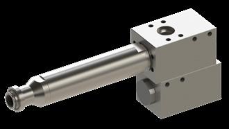
Minimum Shift Flow (Inlet 1-6) 5 GPM
Minimum Shift Pressure (Inlet 7) 300 psi
Flow Coefficient (Cv) (Inlet 1 and Inlet 2) 5 Flow Coefficient (Cv) (Inlet 3) 5.3 Flow Coefficient (Cv) (Inlet 4) 6 Flow Coefficient (Cv) (Inlet 5) 7 Flow Coefficient (Cv) (Inlet 6) 8 Flow Coefficient (Cv) (Inlet 7) 10
Connection (Inlet 1-6)
1-1/2” Code 62 Seal Sub Connection (Inlet 7) 1-1/2” Code 62 Fixed Nose Outlet 1-1/2” Code 62 Seal Sub
Hydrostatic Proof Pressure 9000 psi
Predicted Cycle Life 2500 Cycles
Operating Temperature Range
32˚F to 150˚F Storage Temperature Range 32˚F to 150˚F
Acceptable Operating Fluid Types
Water or mineral oil-based drilling control fluid
None US Patent 9,915,275
Mounting Restrictions
Maximum Operating Depth 15,000 ft
BILL OF MATERIALS

A276 TP 316 (316 SS)
UNS S21800 (Nitronic
UNS S21800
Item Number* Description Material 1 BODY
2 INSERT, THREADED A276
60) 3 SHUTTLE A276
(Nitronic 60) 4 SCHS, 5/8 – 11 UNC A453 GR 660 Continued on page 16.1 Mark IV Shuttle Valve Technical Sheet 1 1/2”, 6000 PSI, Stackable and Pressure Biased OUTLET INLET 2 INLET 1 OUTLET INLET 1 INLET 3 INLET 2 Available Configurations: 1-1/2” in low interflow or high interflow configurations with customizable end connections and mounting. OUTLET INLET 1 INLET 2 INLET 4 INLET 6 INLET 3 INLET 5 INLET 7 SHUTTLE -042120-001-16 DRILLING | PRODUCTION | INDUSTRIAL
Available Configurations:
low interflow
6000 PSI,
Biased
BILL OF MATERIALS (CONT.)

SHUTTLE PRESSURE BIASED
SPRING ROD, PRESSURE BIASED
A276 UNS S21800
B637 Alloy N07718 (INCONEL 718)
PISTON, PRESSURE BIASED A479 UNS S32760 (Super Duplex)
DERLIN AF
COMPRESSION MP35N (UNS R30035)
ADAPTER 1” A276 UNS S21800
ADAPTER, PRESSURE BIASED A276 UNS S21800 (Nitronic 60)
ADAPTER, SEAL SUB A276 TP316
INSERT, SEAL SUB, TYPE 2, 1-1/2” MKIV A276 TP 316 (316 SS)
O-RING (ITEMS* 14 - 20) HNBR
of Inlets
Valve, 1-1/2”, Shuttle, MKIV, Stack, C62, Low Interflow, High Drag, Pressure Biased, 3 Inlets, 300 psi Shift
Valve, 1-1/2”, Shuttle, MKIV, Stack, C62, Pressure Biased, Low Interflow, High Drag, 5 Inlets, 300 psi Shift
Valve, 1-1/2”, Shuttle, MKIV, Stack, C62, Pressure Biased, Low Interflow, High Drag, 4 Inlets, 300 psi
Valve, 1-1/2”, Shuttle, Stack, Flange adapter, C62, Low Interflow, High Drag, Pressure Biased, 4 Inlets, 300 psi Shift

Valve, 1-1/2”, Shuttle, MKIV, Stack, C62, Pressure Biased, Low Interflow, High Drag, 6 Inlets, 300 psi Shift
Valve, 1-1/2”, Shuttle, MKIV, Stack, C62, Pressure Biased, Low Interflow, High Drag, 7 Inlets, 300 psi Shift
high interflow
seal kit
category
Mark IV Shuttle Valve Technical Sheet 1 1/2”,
Stackable and Pressure
(Cont.)
Item Number* Description Material 5
6
7
8 WEARBAND
9 SPRING,
10
11
12
13
14
Part Numbers** Description Number
29021
3 29022
5 29023
4 29063
4 29068
6 29069
7 OUTLET OUTLET INLET 2 INLET 1 INLET 1 INLET 2 INLET 3 OUTLET INLET 7 INLET 6 INLET 4 INLET 5 INLET 3 INLET 2 INLET 1
1-1/2” in
or
configurations with customizable end connections and mounting. SHUTTLE -042120-001-16.1 DRILLING | PRODUCTION | INDUSTRIAL **The repair kit part number will match the category part numbers with (-RK) at the end. **The
part number will match the
part numbers with (-SK) at the end.
INLET 2
Available Configurations:
1-1/2” in configurations with customizable end connections and mounting.
FUNCTIONAL DESIGN SPECIFICATION
Maximum Allowable Working Pressure 6000 psi
Minimum Recommended Working Pressure 500 psi
Flow Capacity (Inlet 1 and Inlet 2) 275 GPM
Acceptable Leakage Rate 4 drops per minute
Flow Coefficient (Cv) (Inlet 1 and Inlet 2) 12
Biased Inlet Minimum Shift Flow 10 GPM
Hydrostatic Proof Pressure 9000 psi
Predicted Cycle Life
Operating Temperature Range
1000 Cycles
32˚F to 150˚F
Storage Temperature Range 32˚F to 150˚F
Acceptable Operating Fluid Types
Water or mineral oil-based drilling control fluid
Mounting Restrictions None
US Patent 9,915,275
Maximum Operating Depth 15,000 ft
BILL OF MATERIALS

Item Number* Description Material
1 BODY
A276 TP 316 (316 SS)
2 SHUTTLE, FULL FLOW A276 UNS S21800 (Nitronic 60)
3 INSERT, THREADED A276 UNS S21800 (Nitronic 60)
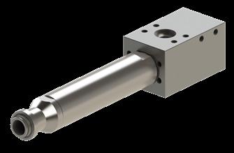
4 ADAPTER, PRESSURE BIASED A276 UNS S21800 (Nitronic 60)
5 ADAPTER, SEAL SUB A276 TP316 (316 SS)
6 SPRING, COMPRESSION INCONEL (X-750)
NUT, GUIDE
ASTM B169 C61400 (BRONZE)
O-RING (ITEM* 8 - 12) HNBR
Part Numbers** Description
Valve, 1-1/2”, Shuttle, MKIV, C62, Inline, 2 Inlets, Spring Biased
**The repair kit part number
with (-RK)
match the category part
the end.
**The seal kit part number will match the category part
with (-SK)
Mark IV Shuttle Valve Technical Sheet 1 1/2”, 6000 PSI, Spring Biased C62
7
8
OUTLET
INLET 1
29062
SHUTTLE -042120-001-17 DRILLING | PRODUCTION | INDUSTRIAL
will
numbers
at
numbers
at the end.
INLET
Available Configurations:
in low interflow or high interflow, SAE and NPT configurations with customiz able end connections and mounting.
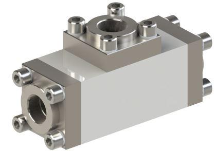
FUNCTIONAL DESIGN SPECIFICATION
Maximum Allowable Working Pressure 3000 psi
Recommended Working Pressure 500 psi
Recommended Maximum Operating Flow 150 GPM
Acceptable Leakage Rate
Minimum Shift Flow
Coefficient (Cv)
Hydrostatic Proof Pressure
Predicted Cycle Life
Temperature Range
Temperature Range
Acceptable Operating Fluid Types
Mounting Restrictions
Patent
drops per minute
GPM
psi
Cycles
to 150˚F
to 150˚F
Water or mineral oil-based drilling control fluid
Operating Depth 15,000 ft
BILL OF MATERIALS

Item Number* Description
BODY A276 TP 316
SLEEVE
SPACER, LI
CAP
V-SEAL
SHUTTLE
S21800 (Nitronic 60)
S21800 (Nitronic 60)
UNS S21800
TP 316
SHCS 1/2 - 13 UNC A286 (GR660)
NORD-LOCK, 1/2”
SMO
O-RING (ITEM* 10 - 12) BUNA N
Numbers**
Shuttle, GEN
Shuttle,
Shuttle,
Low Interflow, 3000 psi
IN,
Out, 3000 psi, Low
Face Seal Out, 3000 psi, Low
repair kit
seal kit part
GEN2 V-Seal Shuttle Valve Technical Sheet 1”, 3000 PSI, Low Interflow
1”
Minimum
0
1
Flow
5
4500
2500
Operating
32˚F
Storage
32˚F
None US
9,719,600 Maximum
Material 1
2
A276
3
POLYETHERETHERKETONE 4
A276
5
PTFE 6
A276
7 FLANGE A276
8
9
254
10
OUTLET INLET
Part
Description 29043 Valve,
2, 1” NPT,
29070 Valve,
GEN 2, 1” SAE
1” SAE
Interflow 29071 Valve,
GEN 2, 1” C62,
Interflow SHUTTLE -042120-001-18 DRILLING | PRODUCTION | INDUSTRIAL **The
part number will match the category part numbers with (-RK) at the end. **The
number will match the category part numbers with (-SK) at the end.
Available Configurations:
in low interflow or high interflow, SAE

NPT configurations with customiz able end connections and
FUNCTIONAL DESIGN SPECIFICATION
Maximum Allowable Working Pressure 3000 psi
Recommended Working Pressure 500 psi
Recommended Maximum Operating Flow 150 GPM
Acceptable Leakage Rate
Minimum Shift Flow
Coefficient (Cv)
Recommended Full Shift Pressure
Proof Pressure
Cycle Life
Temperature Range
Temperature Range
Acceptable Operating Fluid Types
Mounting Restrictions
Patent
drops per minute
GPM
psi
psi
Cycles
to 150˚F
to 150˚F
Water or mineral oil-based drilling control fluid
Operating Depth 15,000 ft
BILL OF MATERIALS

TP 316
S21800 (Nitronic 60)
HI POLYETHERETHERKETONE
S21800 (Nitronic 60)
UNS S21800
TP 316
1/2 - 13
A286 (GR660)
1/2”
(ITEM*
SMO
-
N
NPT, High Interflow, 3000
GEN2 V-Seal Shuttle Valve Technical Sheet 1”, 3000 PSI, High Interflow NPT
Minimum
0
5
Flow
5
500
Hydrostatic
4500
Predicted
2500
Operating
32˚F
Storage
32˚F
None US
9,719,600 Maximum
Item Number* Description Material 1 BODY A276
2 SLEEVE A276
3 SPACER,
4 CAP A276
5 V-SEAl PTFE 6 SHUTTLE A276
7 FLANGE A276
8 SHCS
UNC
9 NORD-LOCK,
254
10 O-RING
10
12) BUNA
OUTLET INLETINLET Part Numbers** Description 29041 Valve, Shuttle, GEN 2, 1”
psi
1”
and
mounting. SHUTTLE -042120-001-19 DRILLING | PRODUCTION | INDUSTRIAL **The repair kit part number will match the category part numbers with (-RK) at the end. **The seal kit part number will match the category part numbers with (-SK) at the end.
Available Configurations:
in low interflow or high interflow
with customizable end
and mounting.
FUNCTIONAL DESIGN SPECIFICATION
Maximum Allowable Working Pressure 5000 psi
Recommended Working Pressure 500 psi
Recommended Maximum Operating Flow 150 GPM

Acceptable Leakage Rate
drops per minute
Minimum Shift Flow Low Interflow 1 GPM
Shift Flow High Interflow
Coefficient (Cv)
Full Shift Pressure
Hydrostatic Proof Pressure
Predicted Cycle Life
Operating Temperature Range
Temperature Range
Acceptable Operating Fluid Types
Mounting Restrictions
GPM
psi
psi
Cycles
to 150˚F
to 150˚F
Water or mineral oil-based drilling control fluid
Patent 9,719,600
Operating Depth 15,000 ft
BILL OF MATERIALS

Number*
-
(ITEM*
Material
TP 316 (316 SS)
S21800 (Nitronic 60)
S21800 (Nitronic 60)
UNS S21800
TP 316
(GR660)
SMO
-
N
psi,
IN/OUT,
Technical Sheet 1”, 5000 PSI, High/Low Interflow NPT
1”
configurations
connections
GEN2 V-Seal Shuttle Valve
Minimum
0
Minimum
5
Flow
5 Recommended
500
7500
2500
32˚F
Storage
32˚F
None US
Maximum
Item
Description
1 BODY A276
2 SLEEVE A276
3 SPACER, HI POLYETHERETHERKETONE 4 CAP A276
5 V-SEAL PTFE 6 SHUTTLE A276
7 FLANGE A276
8 SHCS 1/2
13 UNC A286
9 NORD-LOCK, 1/2” 254
10 O-RING
10
12) BUNA
OUTLET INLETINLET Part Numbers** Description 29042 Valve, Shuttle, GEN 2, 1” NPT IN/OUT, 5000
Low Interflow 29044 Valve, Shuttle, GEN 2, 1” NPT
5000 psi, High Interflow SHUTTLE -042120-001-20 DRILLING | PRODUCTION | INDUSTRIAL **The repair kit part number will match the category part numbers with (-RK) at the end. **The seal kit part number will match the category part numbers with (-SK) at the end.

Gilmore 1231 Lumpkin Road Houston, TX 77043 +1 713 468 8778 INFO@gilmore.com www.gilmore.com


