

Air Walker # 7067-1CREATIVE GIFT 78 PIECES 8+ AGES 1 EXPERIMENT


Parts in your experiment kit: Wow! So many parts! 1 P4 P6 P1 P2 A C P8P7 P3 B P5 P9 16 17 20 21 19 23 22 18 1 2 3 4 6 7 12 13 15 14 11 10 8 9 5
You WILL aLso need:


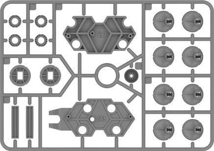


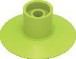
2 KIT CONTENTS Gravity Bugs No. Description Q-ty Part No. A H-BLUE PLASTIC FRAME (parts 1–8) 1 7067-W10-A1B B H-GRAY PLASTIC FRAME (parts 9–15, P5) 1 7067-W10-C1S C H-GREEN PLASTIC FRAME (parts 16-23) 1 7067-W10-B1G P1 H-MOTOR AND SWITCH CIRCUIT 1 7067-W85-A P2 H-SUCTION CUP 4 R12#7067 P3 O-SHORT METAL ROD 1 M10#1155 P4 O-LONG METAL ROD 2 M10#1155-1 P6 O-WHITE GEAR 4 G30#2024B P7 O-ROUND HEAD SCREW M2*5 7 M20-44 P8 O-ROUND HEAD SCREW M2*7 1 M24-11 P9 C-SANDPAPER 1 E41-18 Checklist: Important! YOU MUST REMOVE ALL BURRS (EXCESS MATERIAL) FROM THE PARTS AFTER CUTTING THEM OUT OF THE FRAMES.
1 x AAA battery (1.5 volt, type LR03), small Phillips-head screwdriver (PH0, or PH1 recommended), scissors or diagonal cutters, olive oil or other cooking oil, window or other smooth climbing surface What you will find in the box: Important! 1. Separate the two types of screws (P7 and P8) before starting so that you can tell them apart. P8 is used on battery box cover. 2. Do not remove the parts from the frames until they are needed so that you can locate the numbered parts during assembly. The part numbers are written on the plastic frames. 18 17 16 6 6 8 7 5 4 123 10 13 15 14 12 11 9 P5 x1 P1 x4 P2 x1 P3 x2 P4 x4 P6 x7 P7 x1 P8 x1 P9 16 17 18 2020 21 18 17 16 19 2223 6 6 8 4 x1 P1 Ready? Let’s get building! Burr Burr SANDPAPER
!!!
WARNING! Not suitable for children under 3 years. Choking hazard — small parts may be swallowed or inhaled.
WARNING: This toy is only intended for use by children over the age of 8 years, due to accessible electronic components. Instructions for parents or care givers are included and shall be followed. Keep packaging and instructions as they contain important information. Store the experiment material, particularly the battery-powered motor and assembled model out of the reach of small children.
WARNING! This kit contains sharp points for functional reasons. Do not injure yourself!

Notes on Disposal of Electrical and Electronic Components
The electronic components of this product are recyclable. For the sake of the environment, do not throw them into the household trash at the end of their lifespan. They must be delivered to a collection location for electronic waste, as indicated by the following symbol:
Please contact your local authorities for the appropriate disposal location.
Safety for Experiments with Batteries
→ To operate the models, you will need one AAA battery (1.5-volt, type LR03), which could not be included in the kit due to its limited shelf life.
→ An adult should insert and change the battery. For instructions on how to insert and change the battery, see step 30.
→ Avoid a short circuit of the battery. A short circuit can cause the wires to overheat and the battery to explode.
→ Different types of batteries or new and used batteries are not to be mixed.
→ Do not mix old and new batteries.
→ Do not mix alkaline, standard (carbon-zinc), or rechargeable (nickel-cadmium) batteries.
→ The battery is to be inserted with the correct polarity (step 30). Press it gently into the battery compartment.
→ Always close battery compartment with the lid.
→ Non-rechargeable batteries are not to be recharged. They could explode!
→ Rechargeable batteries are only to be charged under adult supervision.
→ Rechargeable batteries are to be removed from the toy before being charged.
→ Exhausted batteries are to be removed from the toy.
→ The supply terminals are not to be short-circuited.
→ Dispose of used batteries in accordance with environmental provisions, not in the household trash.
→ Be sure not to bring batteries into contact with coins, keys, or other metal objects.
→ Avoid deforming the batteries.
→ Have an adult check the model before use to make sure it is assembled properly. Always operate the motorized model under adult supervision. After you are done experimenting, remove the battery from the battery compartment.
3 SAFETY INFORMATION
Children want to be amazed, understand how things work, and create with their hands!

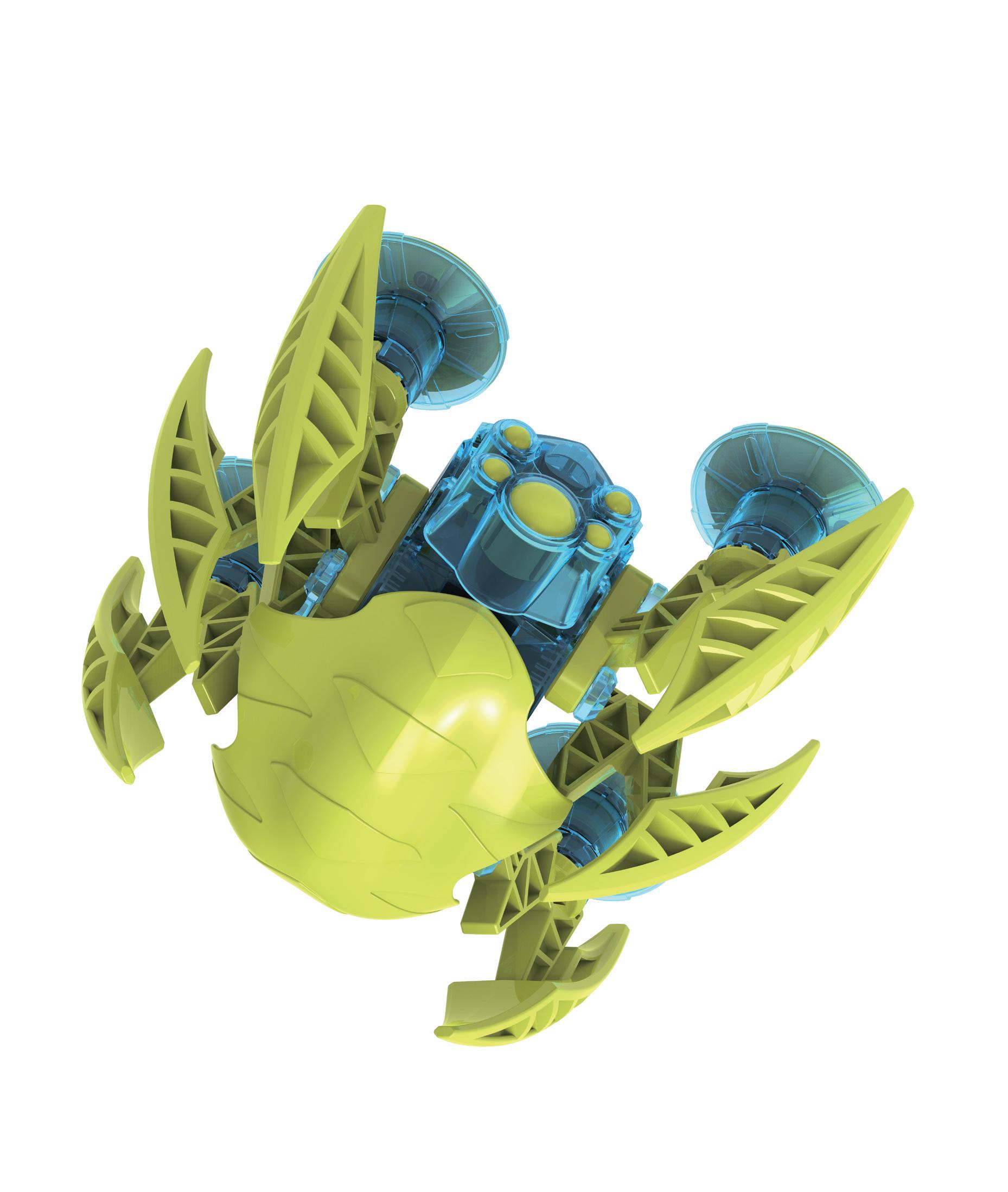
With this science kit, your child can build a robot that walks up a window, while learning the physics behind how it works. Stand by to assist your child with any challenging aspects of assembly or usage.
Putting the Gravity Bug together can be tricky. This is an experiment kit, and you may need to experiment to get your Gravity Bug to climb a window. It’s normal if you find you need to take it apart and try it again. Please read the tips below before beginning and make sure you follow them. Also, scan the QR code here to view helpful assembly and troubleshooting videos.We hope you and your child have a lot of fun experimenting with your Gravity Bug!
instructions with your child and discuss the safety instructions together.
Experiments encourage and challenge children. Stand by to assist your child with any challenging steps of assembly or usage. If your child is working on a table, give them something to work on top of to prevent damage to the furniture.
Particular care must be taken when cutting out the plastic parts, as sharp points can be created. These can be removed with the help of a diagonal cutter and the included sandpaper. If possible, provide your child with diagonal cutters and supervise them.
Do not let the robot model climb so high up a vertical surface that it goes out of reach. Prevent the robot from falling onto people or objects that might be damaged by it.
So much fun!
Scan this QR code to view helpful assembly and troubleshooting videos.

IMPORTANT TIPS
– You must carefully cut the plastic parts out from their frames with diagonal cutting pliers (diagonal cutters) or scissors.

– Remove the parts from the frames only when they are needed.
– Remove excess material (burrs) from the parts before assembling them. Normal scissors do not cut as precisely as diagonal cutters, so you may have to smooth some of the rough edges down with SANDPAPER.

– Do not push or pull on the motor wires. They might break off.

4 Gravity Bugs
A WORD TO PARENTS AND ADULTS
the positive terminal, which is attached to the red wire, into the slot next to the


cut off the burrs using
use SANDPAPER to remove any remaining burrs.

one of the prongs of part 14 as a tool to push the positive terminal all the way into the slot.
Insert the negative terminal, which is attached to the black wire, into the slot next to the symbol.


Negative terminal

Carefully remove all of the excess material (burrs) before assembling. Follow steps 1 – 4 to assemble the battery compartment in the order shown! 1 2 3 4 22 Motor SwitchPositive terminal Negative terminal P1 SANDPAPER First
diagonal cutters or scissors. Then,
1Insert the Positive terminal. Positive terminal 14 STEPS 1 – 4 5 2 4Use
Insert
symbol.
14
Switch
a assemblystep-by-step


Make sure the wires are not twisted here. The red wire should be on the side of the positive terminal and the white wire should be on the side of the negative terminal.
Insert the white wire into the channel in the battery box. Use part 14 to push the wire all the way down, so that it fits snugly in the channel.
Place the motor into the motor compartment above the white wire. Slide the motor toward the center of the battery box until it meets the resistance of the box.


Make sure the wires lie flat under the motor. After this step, the motor gear should spin freely, without touching the white wire.
A capital letter indicates the completion of a subassembly. You are now finished with the battery box. Set it aside for now.
STEPS 5 – 7 6 Gravity Bugs 5 6 7 Insert the switch into the hole.
A find
video
here.
!
14
!


Use SANDPAPER to thoroughly remove the burrs on part 20. STEPS 8 – 12 7 4 8 P2 6 8 9 10 11 12 Place on a tabletop and press down until it clicks. Place on a table top. Then screw together. Repeat four times. 20 x4 x4 x4 x4 Tapered Flat P7 B x4 1. Make sure there is no gap between the blue parts. 2. Tighten the screw. 14 C 19 2 Make sure there is an even gap all around the SUCTION CUP. ! Use the ROUND HEAD SCREW M2*5.!


SANDPAPER Use SANDPAPER to thoroughly re move the burrs from all gear pieces. STEPS 13 – 16 8 Gravity Bugs 13 16 14 Part 14 is used as a tool for aligning the gears. Part 11 is used as a tool for aligning the gears. Symbol facing up Symbol facing up Note the orientation. Line up the trapezoidal notch on part 1 with the matching notch on part 14. Note the orientation. Line up the trapezoidal notch on part 5 with the matching notch on part 11. 5 11 1 14 D 15 ! It is helpful to assemble the gearbox on a tabletop. P4 P4 P3 P5 10 10 Many gears look alike. Part 10 has a circular column on one side and a rectangular column on the other side. !
the gears:


SANDPAPER STEPS 17 – 19 17 18 19 Gently move the gears with your finger. The gears 1 2 3 4 P6 P6 P6 P6 Place the WHITE GEAR (P6) on the LONG METAL ROD in the order shown. ! Make sure the outside teeth of each P6 gear mesh with the inside teeth of the gear below it. 9 9 ! Many gears look alike. Part 9 has a circular column. 12 12 Place two part 9 gears as shown. Use SANDPAPER to thoroughly remove any burrs from the gears. Place two part 12 gears, with the teeth facing down, on the blue pegs as shown. Check the gears: Gently move the gears with your finger. All four WHITE GEAR and the gray gear (P5) should turn together. Check
The teeth of part 12 should mesh with the teeth of parts 9 and 10, but the gears will not turn, because they are locked in place by the alignment tool (part 11).


1313 STEPS 20 – 22 10 Gravity Bugs 20 21 Make sure the wires are tucked out of the way here. 22 ! ! ! Many gears look alike. Part 13 has a rectangular column and a rectangular hole. Make sure the rectangular column of part 13 is pointed down when you place the part. Make sure the tabs on the sides of the battery box slide into the grooves of part 5. 15 15 3 3 A Place parts 3 and 15 as shown. Insert the battery box into the body frame. The battery compartment should face outward, and be oriented toward the top. 13 Place two part 13 gears as shown. Check the gears: The teeth of part 13 parts should mesh with the teeth of the highest WHITE GEAR. The gears will not turn at this point because they are locked in place.


SANDPAPER STEPS 23 – 27 11 10 23 25 24 26 14 9 Place two part 10 gears as shown. Remove any burrs with SANDPAPER. Place two part 9 gears as shown into subassembly D. Remove any burrs with SANDPAPER. through the hole in part 14, then tighten the screw. Next, remove part 14. Carefully place the upper body half onto the lower body half. 12 12 Place two part 12 gears, with the teeth facing up, on the blue pegs as shown. ! ! ! Make sure the circular columns of part 10 are pointed up and oriented toward the center of the gearbox. Do not over-tighten the screw. Make sure the grooves on the upper body half slide onto the tabs of the battery box. Press the gears firmly into place. D 27 P7 Remove the alignment tool, lifting straight up not disturb the gears. 1 2 Check the gears: The teeth of part 10 should mesh with the teeth of part 12. The gears will not turn at this point because they are locked in place.
two more ROUND HEAD
the body as shown
a AAA battery with the correct polarity. To cover, slide the tabs of part 23 into the slots in the battery compartment.

the and polarity
on the battery compartment.
second alignment
it on!
on the switch to make sure the gears turn.
four gray circular columns on each side of the body should now be moving in unison.


If the columns don’t turn smoothly, something is misaligned in the gearbox. Don’t stress! Take it apart, then try to figure it out as you rebuild it. This is part of the fun of engineering!


sure you’ve removed all of the burrs from the gears.
the ROUND HEAD
cover
battery
STEPS 28 – 31 12 Gravity Bugs 28 29 Insert
Remove the
tool (part 11). Use
SCREW M2*7 (P8) to secure the
to the
compartment. AAA x1 23 Turn
Turn
The
Make
P8 11 30 31 Note
markings
Don’t over-tighten the
screws. If
the gears don’t turn when you test it in step
30, loosen these screws a little. P7 P7 Insert
SCREW M2*5 into
and tighten.
Attach two legs to each side of
leg
two locking
will need a total of
bolts.
each bolt in place by using one prong
14 as a screwdriver. To lock, turn the
until it click.
the

Attach the four suction-cup feet to the legs. Pay attention to the direction of the arrow pattern on the tops of the feet when sliding the feet onto the legs.
two drops of olive oil (or other cooking oil) to the rim of each gray gear that attaches to the legs

Oil the rim of
TI
If you switch it on now, and the legs don’t move, take the model apart and build it again. Inspect each of the gray Gears, and carefully remove any burrs with sandpaper.


STEPS 32–34 13 32 33 34
the body as shown. Each
requires
bolts, so you
eight locking
Add
Lock
of part
bolt counterclockwise
(Turn
bolt clockwise to unlock.) 7 7 1618 x2 x2 Lock B
p


STEPS 35 – 38 14 Gravity Bugs 35 36 37 38 Attach the head on the side closest to the switch. 17 17 C Head Switch 21 Done! TROUBLESHOOTING! If you are having trouble getting your Gravity Bug to climb, scan this QR code for help.
OPERATION
TIPS
Experiment: Climbing a window
First, test out your Gravity Bug on a smooth, horizontal surface, like a tabletop. Turn it on and it should walk forward.

Then, stick it to a smooth, vertical surface like a large glass window. Press the suction cups firmly to the surface. The surface must be extremely smooth.
Make sure the surface is clean and dust-free. Cleaning the suction cups or the surface with water can also improve the robot’s grip. Turn on the switch and watch the robot climb. Keep your hands below the robot at first to catch it in case it falls.

Experiment to see which surfaces your Gravity Bug can climb.
CAUTION! Never hold your Gravity Bug between the moving legs. You fingers can be pinched, causing pain. Instead, it is best to hold your Gravity Bug with one finger on the head and the other finger on the opposite side.

Watch me climb!
15
AND
HOW DO Suction Cups WORK?
Suction cups use air pressure to stick to hard, smooth surfaces where a partial vacuum can be created. A suction cup has a cup-shaped surface made of a flexible material, like silicone, rubber, or plastic. When this cup is pressed against a hard surface, the air inside the cup, between the cup and the surface, gets pushed out. The regular atmospheric air outside the cup, which contains many more air particles per unit volume of space than inside the cup, remains the same. These air particles are constantly flying around through the air and hitting things, making a tiny impact, the sum of which is air pressure.
Because there are a lot more air particles per unit volume on the outside of the cup than there are on the inside, the air pressure is higher on the outside. This difference in air pressure is what keeps the suction cup stuck to the surface.

Unstuck suction cup:


Suction cup Air particles


Surface


Pressing suction cup down:
Stuck suction cup: Low pressure
How does the Gravity bug Climb?
By pressing its suction-cup feet onto the window, the Gravity Bug creates a negative pressure there. This means that the air pressure existing there is lower than the environmental air pressure all around it. This negative pressure ensures the Gravity Bug stays stuck to the smooth surface, as the pressure of the atmosphere outside of the suction cups is pushing them toward the surface, while there is virtually no pressure pushing them away.
It is important that the contact between the suction cup and the climbing surface is free of gaps and as airtight as possible. Gaps caused by dust or dirt cause leaks that allow additional air to enter, destroying the negative pressure. Moistening the suction cups can improve the grip. The thin film of water fills in the small gaps and makes for a better seal.
You can create a negative pressure by gently sucking air from an empty water bottle with your mouth. You feel the negative pressure as soon as your lips are pressed against the bottle opening. The force that you can feel is the reason why the Gravity Bug sticks to vertical surfaces. Again, it is important to ensure that the contact between the bottle and your lips is airtight.
? ! CHECK IT OUT 16
Gravity Bugs
Octopus with suction cups

Oter grvit-Defyinanimal
clmber
You have probably seen insects like Flies and spiders effortlessly climb up walls or walk on the ceiling. Unlike the gravity bug, they do not use suction cups, but rather adhesive forces. This physical phenomenon occurs between two surfaces, such as a pane of glass and a fly’s foot. Tiny hairs on the bottoms of insects’ FEET produce a substance of sugars and oils that acts like glue.

Geckos, small lizards
FOUND MAINLY IN WARMER CLIMATES, get their extraordinary climbing ability from elastic HAIRS ON THEIR FEET THAT ARE SHAPED LIKE tiny SPATULAS. Gecko feet have inspired SCIENTISTS AND ENGINEERS TO DESIGN MORE ADVANCED ADHESIVES.


Your Gravity Bug isn’t the only one who uses suction cups. Some frogs, bats, and bugs also use suction cups to get around. Octopuses too are famous for their suckers. They have two rows of suction cups on each of their eight arms, giving them hundreds in total. With these they can move along smooth surfaces or grab food.
Let’s go up the walls!
? ! CHECK IT OUT 17

Section Title

© 2021 Genius Toy Taiwan Co., Ltd. ALL RIGHTS RESERVED R21#7067-1
