
259#1269PCS INVENTING CAN BE LEARNEDINVENTING CAN BE LEARNED EXPERIMENTS INCLUDED EXPERIMENTS INCLUDED20 20 10 10 Compatible with all micro:bit boards up to v2 micro:bit board not included.


Gigo Learning Lab’s complete series includes individual packages and school sets. The special features of Gigo’s Learning Lab are as follows:
INVENTING CAN BE LEARNED
Course levels are designed from elementary to challenging, combining a life sciencesbased curriculum with applications from daily life.
Experiment using Gigo’s building blocks, which can be used over and over again, saving both time and effort. We hope that kids can enthusiastically learn scientific knowledge through fun hands-on experience, developing their problem-solving abilities, as well as a positive attitude towards science. Our mission is to help children apply their newfound knowledge to daily life, furthering their innovational skills and abilities.
Using Gigo’s building block construction-based curriculum, every class has a readyto-assemble model, and includes time designated to promote individual creativity. Boots thinking outside-the-box of the traditional educational framework by learning innovation through play! We are all innately good at something, so we should take into account both individual development and the ability to work as part of a team.
5.4.3.2.1. 1


1 59 67 79 21 93 31 103 39 117 123 125 2 3 65 73 17 87 25 95 37 111 47 53 5 15 5. Monograph (1) 6. Surveyor’s Wheel 9. Elliptical Trammel 10. Monograph (2) 19. Max Bot 18. Motion Sensing Remote Control 17. Robotic Arm 16. Telegraph Machine 15. Monograph (3) 14. Four-legged Beetle 13. Drilling Machine 12. Three-wheeled Motorcycle 11. Crazy Alarm Clock 7. Level Crossing 8. Powered Tram 2. Traffic Lights 3. Cuckoo Clock 4. Drum Machine 1. Metal Detector Meet micro:bit Parts List EnteringIndex the World of Coding Blocks Education Philosophy Index 20. Monograph (4) Appendix Paper card 2


3
Introductory course: Basic version If you are not familiar with programming software and building blocks, you can refer to the basic version of the manual from below link first.
The micro:bit mainboard, which is smaller than a credit card, is a highly flexible and programmable embedded device. It is convenient for young people to carry around and to develop programs. With their creative ideas, may bring tech applications into daily life.
micro:bit is a micro controller board introduced by the British Broadcasting Corporation (BBC) specially designed for youth programming education.
tools:http://python.microbit.org/v/1https://microbit.org/hk/teach/https://makecode.microbit.org/
Meet micro:bit
introduction:http://microbit.org/hk/guide/python/ MicroPython online coding
Blocks Editor online coding: MicroPython
Python is a very popular high-level programming language, also known as an Interpreted language. It is characterized by emphasis on the simplicity and readability of the code.
The Microsoft online graphical coding platform, JavaScript Blocks Editor for micro:bit, can be used without having to download coding tools. A 14-week introductory course is available. Blocks Editor can be used in Windows, MacOS, IOS and Android environments, programs are then uploaded to the device by Bluetooth connection.
https://build.t2t.io/ur?qr=r1Y0qlJuS
The version of Python that BBC micro:bit uses is called MicroPython, you can check the following links to understand how MicroPython operates.
micro:bit is 4cm × 5cm in size, with a built-in 32-bit ARM processor, multiple sensors, Bluetooth and broadcast functions. It has two buttons for input and a 5×5 LED matrix display. It can connect to a computer or tablet using Bluetooth or Micro USB. Online visual coding software is provided for to view and learn operations and applications.
Announcement and online courses (micro:bit V2) https://build.t2t.io/ur?qr=HyLR5I8_w
Compared to high-level languages such as C/C++, Python is more simple, easy to read and uses plain text. It is designed to be use friendly, and as long as you have patience, anyone can learn to use it.
In addition to micro:bit visual coding software, the following coding tools are also available: JavaScript Blocks Editor
MicroPython


4 4 CM 5 CM 2 programmablebuttons Power(3V)portGround back port 5×5 LED Matrix + Light Sensor 3 digital/analogue input/ output rings 4 CM 5 CM 2SensitiveprogrammablebuttonsMicrophoneIndicatorTouchLogo Power(3V)portGround back port 5×5 LED Matrix + Light Sensor 3 digital/analogue input/ output rings BluetoothAntennaSmart 32-bit ARM Cortex M0CPU with Bluetooth Low Energy + TemperatureMagnetometerSensor Micro ConnectorUSB Micro USB ResetBatteryButtonConnector Accelerometer Radio Antenna PowerMicrophoneIndicatorProcessor Micro ConnectorUSB USBInterface ChipSpeakerIndicatorActivityUSB ResetBatteryButtonConnector Compass Accelerometerand Front Side Front Side Back Side Back Side micro:bit V1.5 mainboard micro:bit V2 mainboard


5 Entering the World of Coding Blocks Before you enter the course, please carefully follow the preparatory steps below. [ Step 1 ] Install the micro:bit mainboard in the micro:bit control box. As shown in the pictures below, press down with your thumbs and slide upward in the direction of the arrow. With the micro:bit LEDs facing upward (toward you and visible), slide the micro:bit mainboard into the control box slot. 2.1. ABCEFGH E ABCEFGLED side up EAHD LEDGBCsideup fig.1 fig.2 fig.3


6 Put the upper cover on the control box and slide it back into position. Not inserted fully into the control box. micro:bit inserted face down. Skewed insertion. Correct position Skewed insertion. 4. The micro:bit mainboard should fit flush with the sides as shown in the large picture below. If it is not, please remove it completely, ensure there are no obstructions and then try again. Make sure it is pushed in straight and not skewed. 3. BC F G PC ABCDEFGH ABCDEFGH ABCDEFGH ABCDEFGH ABCDEFGH fig.4


Entering the World of
micro:bit control box
micro:bit control box power switch I/O DuPont (female connector) External input power interface (Micro USB Please use a power supply below
- The toy is only to be connected to equipment bearing either of the following symbols.
- Installing batteries in the core controller
7
As shown below, the micro:bit control box uses six AA batteries, with 1 external input power interface (female micro USB). Use a power supply around DC 5V/2A (a similar power level to a tablet charger, no more). Batteries cannot be charged while in the device, any batteries in the device will stop being used when it is plugged in. There is also a built-in buzzer, 8 sets of I/ O (Gigo type)and 8 sets of I/O DuPont connectors (see the micro:bit pin configuration diagram for details). These I/O interfaces provide micro:bit external connections to the 50X PLANETARY GEARBOX (DDM), 180° SERVO MOTOR (METAL GEAR), LINE SENSOR, FORCE SENSOR, and other devices. Users can also purchase other compatible sensors or servo motors.
- Keep the instruction since it contains important information.
I/O(GigoDC5V/2A)Buzzertype) To PC (Micro USB) or
- Only for use by children aged 10 years and older.
Push the tab in and slide the transparent cover open. This takes some force, so an adult might need to help. Insert the batteries according to the indicated plus-minus polarity. Close the compartment by snapping the cover back on.
Coding Blocks


8 micro:bit master pin configuration I/O pin configuration diagram (for female DuPont connectors)micro:bit Pin-out Diagram GNDGNDGNDP2P20P19+3v3+3v3SPI1SCKMISOMOSI 12C1ANALOGSDASCL IN P1ANALOG IN P0ANALOG IN +3v3P16P15P14P13P12P11P10P9P8P3BUTTONReserved:accessibilityBLEDCol3LEDCol7LEDCol1ANALOG IN P7P6P5P4BUTTON A LED Col 8 LED Col 9 LED Col 2 ANALOG IN ANALOG IN LED side up ABCDEFGHP1P8P12P2P13P14P15P16 GND5V ASDAP20 5V SCLP19 GND P13GNDP14P15GNDP165VEBX5VP14GNDF5VC X P12GNDP2GND5VGP25VDX5VP8GNDHP85VP1GND A partsGigo (DDM)GEARBOXPLANETARY50X (4-PIN)HOLDERLED SENSORFORCE boxControljack GFEDCB


First, connect with a web browser to the micro:bit editor page: Enter<https://makecode.microbit.org/#>thecodingscreenasshown
Blocks/JavaScript: Choose Blocks/JavaScript editor to code. These 2 modes can be Simulator:switched.micro:bit virtual mainboard emulator. When we modify the code, the simulator can check it immediately and present the coding result. Coding blocks: Building blocks to be used during coding. Code editor interface: The main area of coding. Drag coding blocks to this area to Help:code. This function includes information such as Support, Getting Started, etc.
A B C D H I J K L N O F EG M Coding Blocks
below: Interface functions are described as follows: G.C.A.B.D.E.F.H. Go back to the coding introduction page <https://microbit.org/code/> Project: Create a new project or open a program (case). Share: You may share a program with the online community via a web-link.
Entering the World of
micro:bit does not require you to download programming software. Code directly on the web page. (This example uses the Google Chrome browser.)
9 [ Step 2 ] Use the browser to enter the micro:bit programming page.

10 [ Step 3 ] Add new 50X PLANETARY GEARBOX (DDM) block package. First, use the browser to connect to the micro:bit code editor page:Follow<https://makecode.microbit.org/#>thestepsbelowtoinstall:Tip : Right click on the code editor interface, you may choose to delete code, format code or make a screenshot of the entire code and download it. Click on the "Advanced" field.1. More settings: This function includes Project Settings, Add Package, Delete Project, Switch Editor Language, Reset and more. Getting Started: Use this function for the first time to learn how to use the micro:bit coding functions one by one. Show or hide the simulator. Download: click this button to download our coding project to a computer or Namemicro:bit.aproject and save it. Undo / Redo. Zoom In, Zoom Out of the coding screen.M.K.J.I.L.N.O. 1 2 2. Click on “Add Package” (a dialog box will pop up when clicked).


11 Key in the URL link: <https://github.com/gigotoys/gigo-block> and click the search button. 3. Click sensors4. A new toolbar appears. There you will see the C-50X PLANETARY GEARBOX (DDM) special block. 5. 3 4 5 Entering the World of Coding Blocks


Connect the micro:bit control box to your computer: Prepare a USB cable (see figure). The specification is USB Type A male, to USB Micro-B male (provided by the user). Plug one end into the computer’s USB port and the other end (MicroUSB) into the Gigo micro:bit port at the top of the control box (see figure).
2. [ Step 4 ] Download the finished program file to a micro:bit control box.
1. The specification is USB Type A male, to USB Micro-B male (provided by the user) After writing the program, enter the project name, then click Download or Save.
12


13 Tip: You may create a micro:bit-specific program download folder on the disk. Save any downloaded programs you are using to this folder, to make finding program data and creating backups easier. Copy the file saved in the previous step to the Gigo micro:bit CONTROL BOX using the File Manager. 4. Download completed. (Default file save location is >This PC >Downloads)3. Entering the World of Coding Blocks


Reminder: While using "180 degree servo motor (metal gear)" to do programming through micro:bit web page, due to different pre-setting, the program block "servo write" value needs to be written in the range of 20-160 to make sure the motor can be activated.
14
Select "Safely Remove Hardware and Eject Media". Select "Eject MICROBIT". After removing the USB cable, your device is ready for use. 1 2
Tip1: Go to the dropbox link below and download the sample program for model #1269. By dragging it to the programming web page, you can view the code content of the sample program or modify the code, according to your need.
https://www.dropbox.com/sh/ovqmn33oc2v6i7v/AABHe8kmv8eREAW2EnUKwl1Ra?dl=0PleasefollowthestepsbelowtoejecttheGigomicro:bitcontrolboxfrom
There are many factors to consider when the model doesn’t work as expected, such as battery power, model assembly and motor rotation speed. You can adjust motor speed and pause time in the program to find the best solution. the computer. (Screenshots shown are taken from the Windows 10 environment.)
5.1.2.3.
Tip2:


15 Parts List x2 x2 x1 x2 x1 x2x2 x2x1 x2 x2 x1x1x1x1 x1 x1x1 x2 x2x2x1 x2 x4x4 x1 x1x1 x6 x4x6x4x2x4x4 x4x4 x2 x2 x3x2 x2 x2 x1x4x4 x2x2 x2 x2 x4 x2x4x4x4 x2 x50x20x20x2x4x4 x7x4x2x2x2x4x4 33 27 29 3428 26 30 3231 1 6 44 45 35 36 43 4746 11 1312 15 10 16 21 22 23 24 25 17 18 19 20 48 53 49 54 50 5251 38 39 55 56 58 5957 6160 62 6763 6864 6665 69 37 41 40422 3 4 5 14 A B


16 1 B-SHORT PEG 50 2 C-LONG PEG 20 3 C-20mm AXLE CONNECTOR 20 4 C-AXLE 2 5 C-CAM CONNECTOR 4 6 C-TWO-IN-ONE CONVERTER 4 7 C-SHORT BUTTON FIXER 7 8 C-OD8x20mm TUBE 4 9 C-BASE GRID CONNECTOR 2 10 C-LATERAL CONVERTER 2 11 C-FRONT CONVERTER 2 12 C-BENDED ROD 4 13 C-3 HOLE ROUND ROD 4 14 C-3 HOLE DUAL ROD 6 15 C-3 HOLE ROD 2 16 C-5 HOLE ROD 4 17 C-5 HOLE DUAL ROD BOTTOM CLOSED 6 18 C-5 HOLE DUAL ROD 4 19 C-7 HOLE ROUND ROD 4 20 C-7 HOLE PROLATE ROD 4 21 C-9 HOLE ROD 4 22 C-11 HOLE ROD 4 23 C-15 HOLE DUAL ROD 2 24 C-5X5 FRAME 3 25 C-5X10 FRAME 2 26 C-5X15 FRAME 2 27 C-3x13 DUAL FRAME 2 28 C-5x13 DUAL FRAME 2 29 C-BASE GRID 2 30 C-MOTOR AXLE 2 31 C-30mm AXLE Ⅱ 2 32 C-35mm AXLE Ⅱ 2 33 C-60mm AXLE Ⅱ 2 34 C-65mm AXLEⅠ 1 35 C-70mm AXLE Ⅱ 2 No. Description Item No. Qty. 36 C-100mm AXLE Ⅱ 2 37 C-150mm AXLE Ⅰ 1 38 C-WASHER 2 39 C-WORM GEAR 1 40 C-ROD CONNECTOR 1 41 C-20T GEAR 4 42 C-40T GEAR 4 43 C-60T GEAR 2 44 C-80T GEAR 1 45 C-145° CRANKSHAFT GEAR-A 1 46 C-145° CRANKSHAFT GEAR-B 1 47 C-GRIPPER 4 48 C-20T BELT 4 49 C-21T BELT 4 50 C-LARGE BODY PIECE A 2 51 C-SMALL BODY PIECE LEFT 2 52 C-SMALL BODY PIECE RIGHT 2 53 C-LARGE BODY PIECE B 2 54 C-MAIN BODY PIECE 2 55 C-40T WHEEL FRAME 4 56 C-60T WHEEL FRAME 4 57 C-TWO-IN-ONE FIXTURE 4 58 C-CLAW PIECE A 2 59 C-CLAW PIECE B 2 60 B-PEG REMOVER 1 61 C-FORCE SENSOR 1 62 C-Gigo micro:bit CONTROL BOX 1 63 C-180° SERVO MOTOR (METAL GEAR) 1 64 C-50X PLANETARY GEARBOX (DDM) 2 65 C-LED HOLDER (4-PIN) 1 66 C-LAMPSHADE 1 67 C-LED HOLDER (4-PIN) 1 68 C-LED HOLDER (4-PIN) 1 69 C-LINE FOLLOWER SENSOR 2 No. Description Item No. Qty. 7061-W10-Q1D7416-W10-C1D7413-W10-M1D7413-W10-O1D7413-W10-N1D7026-W10-L1S17125-W10-A1SK7061-W10-U1D7406-W10-A1D7413-W10-J1D7413-W10-I1D7413-W10-Q1D7413-W10-Z1D7413-W10-P1D7407-W10-C1D7404-W10-C3D7404-W10-C2D7413-W10-X1D7413-W10-W1D7413-W10-K2D7026-W10-Q2D7413-W10-Y1D7404-W10-C1D7061-W10-V1D7061-W10-Y1D7061-W10-X1D7026-W10-I1SK7400-W10-G2D7061-W10-W1D7061-W10-G1D7413-W10-S1P17026-W10-H1R7413-W10-T1R7061-W10-C1R7344-W10-C2B 1247-W85-B31269-W85-B1Y1269-W85-B1G7050-W10-I1R1269-W85-B1R7412-W85-A1247-W85-D31269-W85-A1246-W85-C7061-W10-B1Y7445-W10-B2G7445-W10-B1G7445-W10-D1S7444-W10-A1D7446-W10-B1O7445-W10-C1G7443-W10-A1R7446-W10-A3Y7446-W10-A2Y7446-W10-A1Y7446-W10-C2D7446-W10-C1D7411-W10-G1D7411-W10-C2D7411-W10-C1D7328-W10-G2O7026-W10-W5Y7346-W10-C1B7026-W10-D2R7026-W10-L2D7344-W10-A1DR12#36207026-W10-P1D7413-W10-L2D
The models will often have several gear wheels installed in a row, or gear train. In order for the models to work well, thesae gears will have to mesh well. Otherwise, the force from one gear wheel won’t be properly transferred to the next.
A. Pay attention to the hole: B. B-Peg remover: C. Gear wheels: Here are a few tips for assembling and using the models. Read them carefully before starting. NG! (without space) OK! (with space) For more assembly tips, please refer to
Parts List: TIPS AND TRICKS: When fixing gears onto the frame with drive axle be sure to keep a proper space (about 1mm) between the gear and the frames (Fig. 2). And try to turn the gear to ensure every gear in the gear train turning smoothly so that the least friction will be created and most efficient power transmission can be expected. Fig.1 Fig.3Fig.2 Fig.4 Using peg remover to pull peg off as Fig.3 shows. Using peg remover to pull axle off as fig.4 shows.


Metal detectors use the principle of electro-magnetic induction fields. The detector on the micro:bit kit, has a coil that generates an electromagnetic field by passing rapid, alternating current through it. This field is a known value and changes in it are used to detect anomalies as it passes over other metallic or magnetic objects. As magnetic objects pass into the field, for example mines, coins or any large enough iron particles, an “eddy” is created in the current. An eddy is like a whirlpool and can also be used to describe water. The eddy causes an anomaly in the induced-field by means of its own magnetism, which changes the frequency of oscillation. The change in oscillation is translated to a change in frequency of the buzzer.
The metal detector in this lesson is a model which mainly uses the micro:bit’s built-in magnetometer. The model is sensitive to iron, cobalt, nickel, or other magnetic substances such as computers, mobile phones and especially magnets. Each micro:bit may have a different level of sensitivity to magnetic forces, and the sensor readings may be different among different devices. Users may wish to adjust the sensitivity settings that trigger sounds of the buzzer, according to their own situation.
What are the properties of metal? Why are we looking for it during treasure hunts as well as security checks?
Electromagnetic Induction Scientific Application
Brainstorming 17
Metal detectors are mainly used for two purposes - discovery and prevention, such as: archaeological treasure hunt, mineral exploration; immigration security checks, detection of contraband in various government agencies and entertainment venues. Nowadays, they are also used in food and plastics processing industries to detect whether metal impurities have been accidentally mixed in with the products. The construction industry also uses metal detectors to detect the placement of metal lines in cement, walls and ceilings, and the location of steel bars.
DailyApplicationDaily
DetectorMetal
1


18 Parts List 5 5 3 4 6 12 ×2×2 22 18 18 x10 1 x4 12 x3 18 x1 16 x2 22 x1 62 x2 23 x18 2 x1 28 x2 53 x1 14 x1 10


19 1 Metal DetectorDone OperationModelVideo Program Example Smart Manual Web Service


20 1 2 3Evaluation AssembledModel ExperimentComplete CreationModel CreativityHands-on ExperimentHands-on Is there any magnetic substance around you that makes the metal detector producing a stronger reaction? Code a program to produce different detection reactions.
There can be two reasons for this: Despite being color blind, red and green, in the eyes of a dog, have different levels of brightness. Just as differences can be distinguished on a black and white television; another possibility is that dogs can distinguish the positions of the light signal.
The idea to have a traffic light signal-man at pedestrian crossings began in East Berlin, Germany, 1961. The original intent was to remind pedestrians crossing the road. The little red man light now signals that crossing is forbidden; the little green man signals that crossing is possible. However, the traffic light men at that time had a fixed walking posture, without movement. In Taiwan, 1998, the Taipei City Government added a timing function to the traffic light man, and further developed the moving little green man that we are now familiar with. The little green men were well received. Afterwards other cities adopted them one after another, and they were even exported to other countries such as the United States and Japan.
It might not be obvious to us that traffic lights in our daily lives have fixed locations. Two-thirds of the world's countries drive on the right hand side of the road (left-hand drive), the red light is on the left and the green light is on the right; the other third of countries drive on the left hand side of the road (right-hand drive), where the red light is on the right and the green light is on the left. Regardless of whether you are on the left of right, as long as the traffic lights are vertical, the red light is always at the top, the green light is always at the bottom. In this way, dogs may distinguish the correct lighting signal and know whether to cross a road or wait.
Traffic Lights Colors and Positions Scientific Application
Are there any more interesting traffic light designs besides a walking person and waiting person?
Brainstorming 21 2
DailyApplicationDaily
If dogs are color blind, how does a guide dog distinguish among different colored traffic lights?


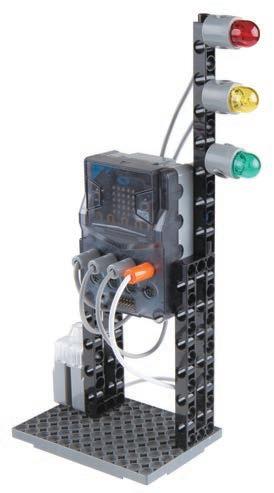
22 Parts List Sensor Light-cLight-bLight-a SensorLight-cABCDEFGHLight-bLight-a How to replace the lampshade presspress 5 3 4 2 1 x1 65 x1 67 x1 68 x1 23 x2 27 x1 29 x1 61 x1 62 x8 1 x1


23 Traffic Lights2 OperationSmartDoneManualWebServiceModelVideo Program Example


24 1 2 3Evaluation AssembledModel ExperimentComplete CreationModel CreativityHands-on ExperimentHands-on Add a flashing function to the traffic light when it lights up. Change the model to make the traffic light horizontal, and match the lighting pattern of your country's traffic lights.
The cuckoo clock originated in the Black Forest region of southwestern Germany. Through fine gear design and the craftsmanship of generations of wood-carving masters, the local production of cuckoo clocks became world-famous.
DailyApplicationDailyCuckoo
Brainstorming 25 3
In modern times, where mobile phones are present everywhere, it has gradually become a norm to have no clock at home. Have you ever seen those clocks where a little-cuckoo pops out to announce the time? Whenever the long hand points to 6 and 12, the small wooden door at the top of the clock opens, and a wooden cuckoo comes out to sing a little song or “cuckoo” noise. It is called a “Cuckoo clock" because the bird was originally a Cuckoo bird that makes a “ku-koo” sound.
In addition to timekeeping aspects of design, we can also use modern dynamic mechanical principles to implement new methods of operation, to indicate the passing of one hour. Now each cuckoo clock can have its own story!
Clock Radio Frequency Scientific Application
Buzzersmicro:bit?are divided into two types: “active” and “passive”. Active refers to a sound of a fixed frequency can be produced through the internal oscillator. As long as an external voltage is supplied, the multi-vibrational structure will operate; while Passive means that there is no internal oscillator source, therefore one must provide a driving signal of a certain frequency from an external circuit. Our extended version uses a passive buzzer that can be oscillated by triggering the micro:bit code.
The micro:bit program only has a wait function. Try it out: How can you write the function of a clock on


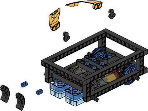
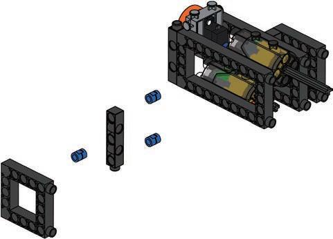
26 Parts List How to adjust motors to vertical position Please make sure the hole on motors are vertical. 5 3 4 6 12 ×2 100mm x1 42 x1 43 x1 45 x1 46 x2 53 x2 51 x2 54 x1 55 x2 52 x1 56 x1 62 x1 63 x4 14 x1 16 x2 17 x4 18 x4 12 x2 19 x2 13 x3 24 x2 27 x1 28 x1 30 x2 31 x1 32 x1 36 x3 41 x1 40 x26 1 x3 2


27 3 Cuckoo Clock 30mm 30mm 35mm 11 10 9 7 8 51 52


28 Motor ABCDEFGHMotor GND5V 15 13 14 16 12 51 52


Done 29 3 Cuckoo Clock Smart Manual Web OperationModelServiceVideo Program Example


30 1 2 3Evaluation AssembledModel ExperimentComplete CreationModel CreativityHands-on ExperimentHands-on Use the program to change the steering angle of the 180° SERVO MOTOR (METAL GEAR) to create different movements. Experiment with the configuration options, for example try changing the 180° SERVO MOTOR (METAL GEAR) into a 50X PLANETARY GEARBOX (DDM) box to see what the effect is.
Reciprocating Mechanism Scientific Application
Since the hand is a good striking tool, why are most modern drums kits hit with a stick?
DailyApplicationDailyDrumMachine
The earliest musical instrument sounds were made by striking an item by hand. Tambourines are a commonly found example. The African tambourine can be traced back to 500 AD, and it is believed that it was spread via trade routes up and down the Nile region to the Middle East, and then the rest of the world. In the beautiful lands of West Africa, the aborigines still express their feelings through song. Whether it is a sacrifice, banquet or celebration, they show gratitude by dance and song. Guests and observers will be able to strike items around themselves to join in the brisk rhythm, so everyone can create music together. In this way, African tambourines formed an important part of African society, as they still do today. The lives, religions, and cultures of many Aboriginal tribes still find use for the tambourine today.
Brainstorming 31 4
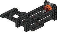
A reciprocating motion is created by using linkages. Linkage mechanisms come in many different types involving, two, three or more linkage bars. In a reciprocating mechanism, like this one, there is only one joint between links on two connecting rods which generates a linear motion. Linkages allow engineers to permit some movements while restraining others. Each structure (two bar linkage, three bar linkage or more) has its own principles, some of which we will see later. The combination of mechanical principles may be used to form a variety of new movements.


32 Parts List Hole B 5 7 3 8 4 6 2 1 x1 53 x2 54 x2 56 x2 57 x1 58 x1 59 x1 62 x1 64 x1 66 x1 67 x1 65 x1 14 x4 3 x2 5 x1 16 x3 12 x2 19 x1 13 x1 24 x1 25 x2 26 x1 28 x1 31 x1 34 x2 33 x8 1 x2 2 x3 42 x2 43 x1 45 x1 46 x2 50 x3 41 30mm 65mm


33 4 Drum Machine Hole B Hole B A 15 13 14 12 11 9 10×2 ×2 60mm 57 57 59 58


34 Please refer to p.126 for tips on fixing the LED covers. Light-bLight-a Motor ABCDEFGHLight-bLight-a Motor 19 17 18 16


Done You may need a flashlight to run the model properly. 35 4 Drum Machine Smart Manual Web OperationModelServiceVideo Program Example


36 1 2 3Evaluation AssembledModel ExperimentComplete CreationModel CreativityHands-on ExperimentHands-on Use light sensors and the A button to change the frequency of drum hits and design your own rhythm. Read the numbered musical notation by yourself, and compose a simple piece of music by writing a program.
37 ReviewModel 5 Monograph 1 Please use the models and principles you have seen so far, to design a facility that can be seen in an amusement park. 1. Metal Detector 3. Cuckoo Clock 2. Traffic Lights 4. Drum Machine


38 2 1 3 ConceptDesign Evaluation DesignModel CreationModel Winner! My Artwork


Infrared sensors are manufactured using the principle of infrared reflection. They are commonly used in automatic flushers, automatic faucets, hand sanitizer, and hand dryers. When a human body or an object blocks the area of infrared radiation and causes a reflection, it will trigger the infrared solenoid valve and can be used to activate a pre-defined action. Due to the different spectra (here black and white on card or paper), the infrared only reacts to the spectrum of an object located in a particular area. For example, IR tracking sensors do not respond to objects in the black part of the visible light spectrum. Therefore, it is possible to sense distance changes via a paper card with alternative black and white strips.
Brainstorming 39
The Surveyor’s Wheel (measurers wheel, distance measure wheel) is known by many names. It is pushed by the person measuring along the path to be measured. The contact wheel is pushed along the ground and turns uniformly with the distance covered. As it turns, a device counts the number of turns made by the contact wheel, then calculates the distance covered by multiplying the number of turns by the circumference of the wheel. The resulting distance is then shown on a screen. The advantage of this method is that it is very simple and to operate, and it can easily measure the length of curved surfaces and arcs. However, it is not always possible for the operator to keep an exactly straight line, and there may be some data errors if the surface is uneven or if the wheel does not turn by friction with the ground (like on a slippery surface).
The measuring wheel of this lesson uses a gear to transform vertical wheel rotation into horizontal rotation. An infrared sensor is then used to detect a piece of paper or card with alternating black and white strips. From this it calculates the length in centimeters and displays it on the micro:bit 5 × 5 Usersmatrix.may choose to display the cumulatively measured distance through a program, or input the distance to be measured in advance whereupon the micro:bit will count down to zero and an alarm will sound.
What other measurement tools are there besides the distance measuring wheel? What are their advantages and disadvantages?
WheelSurveyor’s
6 DailyApplicationDaily Infrared Sensor Scientific Application


40 ※ To be used with the distance measuring wheel paper card on page 125. 6-1 Parts List How to connect the BELT OK Side view Front View 5 3 4 2 1 35mm 35mm 22 6 6 ×148 x21 1 x2 12 x3 14 x1 16 x1 22 x1 35 x2 38 x1 41 x3 42 x1 43 x1 48 x1 54 x1 55 x1 62 x1 69 x1 25 x1 4 x2 6 x2 26 x2 27 x2 32 x1 24


41 6 Surveyor’s Wheel Back side Front side Front side Side view ABCDEFGHSensor GND5V SideKeepviewa10~20mm gap between the card and IR sensor. Sensor 10 9 7 8 6 70mm


Done 42 OperationModelVideo Program Example Smart Manual Web Service


43 6 ※ To be used with the distance measuring wheel paper card on page 125. 6-2 PartsSurveyor’sList Wheel x14 1 x17 2 x4 12 x1 14 x1 16 x2 18 x2 20 x1 35 x1 38 x4 41 x1 43 x2 48 x2 50 x2 55 x1 62 x1 69 x2 21 x2 23 x1 4 x2 6 x2 24 x2 27 x1 33 9 5 7 3 8 4 6 12 ×2 60mm 70mm 2121 6 6 18 18


44 Please refer to p.126 for tips on connecting the belt. Front View Keep a 10~20mm gap between the card and IR sensor. ABCDEFGHSensor GND5V Set the black and white cardboard on back side. Sensor 15 13 14 12 11 10 16 ×2 ×148


Done 45 6 Surveyor’s Wheel OperationModelVideo Program Example Smart Manual Web Service


46 1 2 3Evaluation AssembledModel ExperimentComplete CreationModel CreativityHands-on ExperimentHands-on Take a ruler or a measuring tape to measure, observe and record the accuracy of the distance measuring wheel and its possible error, then adjust the values of the program to calibrate it. Change the structure of the handle to design a measuring tool that is more ergonomic.
Inertia Scientific ApplicationLevel Crossing
The Newton's first law of motion states that the object either remains at rest or continues to move at a constant velocity, unless acted upon by another outside force. The Newton's first law is also known as the law governing inertia. Inertia is the resistance of any physical object, to any change in its position and state of motion. You can observe inertia in any object and with the heavier the object, the greater the inertia. On Earth, inertia is often affected by external forces (gravity, friction, air resistance), so it makes the movement of objects slower over time, and finally stationary.
Trains cannot stop like a regular vehicle. A train that travels at 80 km/h will have a braking distance of 2 km due to inertia. Therefore, the protection of railway level crossings is significantly more important. Barriers, gates, red lights, and warning sounds were all added to alert of possible dangers near railroad crossings. The model in this lesson simulates a situation when the train passes (triggering the IR sensor) and the railroad crossing begins to operate.
DailyApplicationDaily
In the early days when trains first appeared, railway level crossings were all manuallyoperated, with staff to remind pedestrians to pay attention to safety requirements.
Inertia is exerted on all objects. Think about it, why can cars brake over a relatively short distance, but trains cannot?
Whenever a train is about to pass, the person on duty would wave a red flag, signaling all vehicles and pedestrians to stop crossing and to clear the track.
Brainstorming 47 7


48 Parts List 17 5 7 3 4 6 2 1 ×2 ×2 30mm x1 55 x1 56 x1 62 x1 64 x1 65 x1 67 x1 66 x1 69 x1 15 x1 16 x2 17 x1 10 x2 18 x4 12 x1 19 x2 21 x2 22 x1 23 x3 24 x2 27 x2 28 x1 31 x2 33 x1 40 x1 29 x7 1 x12 2 x1 41 x1 42


49 7 Level Crossing 13 1112 10 9 8 60mm 60mm 22 21 21 22 18


50 Light-a MotorLight-b Sensor ABCDEFGHLight-bLight-a Motor Sensor GND5V 15 17 18 14 16


Done 51 7 Smart Manual Web Service Level Crossing OperationModelVideo Program Example


52 1 2 3Evaluation AssembledModel ExperimentComplete CreationModel CreativityHands-on ExperimentHands-on Simulate a train for the level crossing and observe if the number of seconds that the level crossing is lowered enough for a train to pass. Use the remaining blocks or items at hand to set up other possible objects around the level crossing (e.g. trains, tracks, fences).
Sensing & Decision Scientific Application
A motor is generally divided into three parts: a casing, a stator and a rotor. After the stator is fixed to the casing, the change of the magnetic field can drive a rotor. The rotor of the motor usually has a very high speed and a very small torque. Therefore, a motor will add a deceleration function to reduce the speed and increase the torque through gear ratios.
Brainstorming 53 8
The different directions of electric current can change the positive and negative rotation of the motor; while the magnitude of the voltage can change the speed of the motor. If a tracking vehicle easily derails when it runs, you should examine whether adjust the motor speed will allow it time to adapt to changes in the track.
Different color lights have different reflective properties. Black has the lowest reflectivity; while white has the highest. The photoelectric crystal in the IR sensor, after sensing, will output different potentials to differentiate the two colors. The number of infrared modules will also influence the stability of the self-propelled vehicle. At least two infrared modules must be used in order to identify the direction. Two IR tracking sensors are on either side of the line. The vehicle body is in the center. The control box decision process is as follows: go straight forward; right-side IR tracker detects the line, vehicle responds by left adjustment. Left-side IR sensor now detects line, vehicle body responds by turn right adjustment.
Powered Trams can run automatically and travel along a planned track on the ground. Using an infrared emitter, and infrared photoelectric crystal sensor the intensity of the reflected light determines whether the tram is on course. A controller is used to correct and adjust movement directions of the vehicle so that it can continue to run automatically on the track.
DailyApplicationDailyPoweredTram
A tracking vehicle does not have a steering wheel, and its front wheels do not turn. How does it turn?


54 Parts List Bottom view 5 7 8 4 6 35mm 30mm 30mm 60mm30mm x2 42 x4 49 x2 51 x1 54 x4 56 x1 62 x2 69 x2 64 x2 12 x3 19 x3 13 x2 20 x4 22 x2 26 x2 31 x2 32 x2 33 x2 52 x1 53 x2 41 x2 48 x1 50 x25 1 x7 2 3 12 x4 6 x2 10 x2 21 x1 14 x1 18 22 21 21


55 8 Powered Tram 13 14 12 11 10 35mm60mm 51 51 52 52 9 22 22 22


56 Please refer to p.126 for tips on connecting the belt.ABCDEFGHMotor-bMotor-a Sensor-aSensor-b GND5V Sensor-bSensor-aMotor-a Motor-b 20 19 15 17 18 ×148 ×249 16 ×2


Done 57 8 Smart Manual Web Service Powered Tram ※ Black strip is provided by the user.15~20mm OperationModelVideo Program Example


58 1 2 3Evaluation AssembledModel ExperimentComplete CreationModel CreativityHands-on ExperimentHands-on Make a black line on the ground to let the tracking vehicle travel along the track. Change the thickness and curvature of the track. Observe and record the type of path that is most suitable for the tram.
2. Path: Path of a given tracking point.
Reciprocating and Rotating Motion Scientific Application
DailyApplicationDailyEllipticalTrammel
Is there any mechanical structure in daily life that utilizes a combination of motions? With what combinations of motions are they formed?
Machines exist to reduce the amount of human effort required to complete a task. We have seen many mechanisms and engineering techniques separately, but now we will begin to combine some. For this variation on a reciprocating mechanism, each body is connected so it pivots in at least two locations.
When a machine is in operation, it will initiate a given movement. Common types of motions are linear, rotational, back and forth, and reciprocating. Linear means that an object moves along a straight line; rotational motion means that an object will rotate with a fixed central point; back and forth means that an object keeps a constant distance to a fixed point in an arc within a certain range; reciprocating motion refers to an object moving in a fixed range along a straight line repeatedly (like a piston). When different motion types are adjusted and combined through a body, a new type of motion will be created.
Brainstorming 59 9
3. Motion: Describes the movement of the link. The model in this lesson uses a combination of rotating and reciprocating motions, combined with path tracking, allowing a plotter to draw geometric figures. You can adjust the speed of the two motors, the position of the levers, the thickness of the pen or colors etc; to draw a variety of different geometric figures. Linear guide Fixed point
1. Function: The relative motion between joints at the two ends of a fixed link.
Pieces will be able to move relative to each other to achieve the correct movement. This is similar to the Linkage in L4, but with more “links”. The function of this linkage is to pull a crank through a rotation of one link, so that the another can swing, rotate or reciprocate.
Linkages are very versatile and can be used to create many different types of motion for different uses and effects. There are some specific terms we must understand before we can know how linkages work.


60 ※ Use the microcomputer plotter paper card on page 126. Parts List Top Closeviewto the edge 3 4 2 1 70mm 70mm x12 2 x1 42 x1 44 x1 62 x2 64 x2 14 x5 3 x2 5 x4 7 x2 17 x2 9 x2 10 x2 12 x3 19 x2 13 x1 23 x1 22 x3 24 x2 25 x1 27 x2 28 x2 35 x1 32 x1 30 x1 39 x3 41 x2 29 x11 1


61 9 Elliptical Trammel Hole B 5 7 8 6 27mm 35mm


62 Back side Motor-a ABCMotor-bDEFGH Motor-b Motor-a 13 12 11 10 9


Done 63 9 Smart Manual Web Service Elliptical Trammel ※ Pens and rubber bands are not included. Please refer to the model operation video for the installation. OperationModelVideo Program Example


64 1 2 3Evaluation AssembledModel ExperimentComplete CreationModel CreativityHands-on ExperimentHands-on Use different color pens to draw different images on the same piece of paper. Modify the program to make one of the motors perform an intermittent motion. Observe the effects on the output image.
65 ReviewModel 10 Monograph 2 Please use the models and principles you have learned about so far to design a ball-catcher that can sense whether a ball has been thrown-in or not. 6. Surveyor’s Wheel 8. Powered Tram 7. Level Crossing 9. Elliptical Trammel


66 2 1 3 ConceptDesign Evaluation DesignModel CreationModel Winner! My Artwork
DailyApplicationDailyCrazy
Alarm Clock
Random Variable Scientific Application
One of the main functions of an alarm clock is the alarm ringtone. Even the new vibration or LED display alarm clocks still have to produce a sound. In addition to monotonous alarm ringtones and electronic sounds, you may also use classical music, insect buzzes or bird songs, or even heavy metal music! You are now able to personalize these alarms according to your taste. There are many reasons for oversleeping, such as staying up too late at night, being too tired from the previous day, lack of sleep, or forgetting to set an alarm. Even if an alarm is set, it is very easy to turn it off and continue to sleep in the morning (snooze function). The most common reason for oversleeping is actually going back to sleep after turning the alarm off!
What things in life are related to randomness? Randomness means that the target, motivation, rules and other methods cannot be predicted. A random process refers to a process that repeatedly generates indefinite factors. A random variable is a variable obtained in a given sample space, and the value of this variable cannot be predetermined. Its value can only be estimated within the given range. Randomness can only obtain non-deterministic values. In order to let the crazy alarm clock run around, we will use the concept of random access in the program, so we can’t determine the next direction the clock turn to.
Brainstorming 67 11
If you want to avoid going back to sleep, you may set the snooze mode or use a type of alarm that is difficult to turn off. The snooze mode will repeat the alarm every 5 minutes, or you may set a different desired interval. But even if an alarm clock is set to go off every 5 minutes, there are still some people who just will not get out of bed. In this lesson, we will design a crazy alarm clock. When the time comes, the alarm clock will run away quickly, while sounding its alarm. It will also find a corner to hide. If you don't want to move the table or chair, you will have to get up and grab it fast.


68 Parts List 5 3 4 6 2 30mm 60mm 21 21 21 x4 12 x2 16 x2 19 x3 21 x4 41 x2 42 x1 54 x1 25 x2 6 x2 24 x2 31 x2 33 x4 2 x6 1 x2 56 x2 57 x1 58 x1 59 x1 62 x2 64 1


69 11 Crazy Alarm Clock 910 7 68 6


70 Motor-a Motor-b ABCDEFGH Motor-aMotor-b 13 12 11 57 57 59 58


Done 71 11 Smart Manual Web Service Crazy Alarm Clock OperationModelVideo Program Example


72 1 2 3Evaluation AssembledModel ExperimentComplete CreationModel CreativityHands-on ExperimentHands-on Write a program to add different running modes to the alarm clock. Change the outward appearance of the alarm clock so that it can tip over forward or backward, and yet continue to run.
Cars have a long history. First, rickshaws appeared, then smaller, steam-powered vehicles, and finally cars. At that time, power transmission devices were already wellSmaller,developed.steam-powered vehicles first originated in France, 1769 where Mr. Cugnot made the first steam powered vehicle called a “fardier à vapeur”. Next, larger steam powered trains emerged from the UK. Later still, more train designs came forth from Germany and the United States. Engines were driven first by steam, then electricity and finally diesel.
Slip and Steering Scientific Application
The first motorbike ever created for sale, was a three-wheeled design by the British in 1884. It was not successful and there were funding problems, so it never saw widespread adoption.
In 1885, German inventors began to use an internal combustion engine to create a new type of locomotion that differed from the principle of bicycles, but that too was never released to the market. Then, also in Germany in 1894, the first locomotive vehicle was released for sale. This is the first type of vehicle formally referred to as a motorcycle. The vehicle in this lesson is driven by motor but steered by turning of the wheels. You may select the mode of operation through the A or B buttons, or try to code a different way of traveling.
How many 50X PLANETARY GEARBOX (DDM) and 180° SERVO MOTOR (METAL GEAR) are required to achieve steering and slipping mechanisms, respectively?
Brainstorming 73
There are two ways to turn - steering and differential steering. Like a normal car, tracked vehicles will have a transmission device to control the forward (or backward) movement of the car body. But there are no front wheels to turn so it is not such a simple mechanism. Construction crawlers or tanks use differences in the speed between the two tracks to twist (or what appears to be a slip). This is formally referred to as differential steering. The double transmission devices (one for left and one for right) drives the left and right wheels (or tracks) to achieve a different angle of twist, and to provide forward and backward movement. Some tracked vehicles can even turn on the spot, where it seems that they are slipping.
12 DailyApplicationDailyThree-wheeledMotorcycle


74 Parts List FrontKeepViewthegear close to upside. Back side Hole B How to adjust motors to vertical position Please make sure the hole on motors are vertical. 5 3 4 6 2 1 ×2 27mm 17 17 x3 42 x1 45 x1 46 x1 48 x1 63 x1 64 x6 14 x2 6 x1 16 x6 17 x2 12 x4 19 x2 13 x2 24 x2 27 x1 30 x1 31 x1 34 x1 35 x1 36 x1 40 x4 41 x6 2 x2 5 x26 1 x1 51 x1 54 x2 56 x1 55 x1 62 x1 52 x1 53 x2 50 x1 65 x1 67 x1 66 ×148 Please refer to p.126 for tips on connecting the belt.


75 12 Three-wheeled Motorcycle Please refer to p.126 for tips on fixing the LED covers. Front side Keep 2mm gap each side Front View 910 7 8 12 11 17 17 18 18 100mm 65mm


76 Motor-a Light-aMotor-bLight-b ABCDEFGH Light-a Motor-aLight-b Motor-b GND5V 15 17 13 14 16 6 6 51 52


Done 77 12 Smart Manual Web Service Three-wheeled MotorcycleModelOperationVideo Program Example


78 1 2 3Evaluation AssembledModel ExperimentComplete CreationModel CreativityHands-on ExperimentHands-on Change the program content to add a new type of action. Work with others to write your own remote-control codes.
There are many kinds of engineering trucks. Generally, heavy transportation equipment uses liquid with a pressure pump, using an extremely high pressure to transfer the liquid into the equipment to move machine parts.
The hydraulic pipe connects the various hydraulic components, drives the pressure pump via a motor or an engine, and controls the operation of the entire truck by controlling the liquid flow and pressure of each valve. We have seen excavators in many movies, but to actually use it to drill a cave is impossible with the current stage of technology. Mainly because of safety considerations, we can't be sure that the area that has been drilled won't collapse, burying people and the machine inside.
Generally, the steering controls of a car are at the front of a chassis. Steering characteristics can be divided into three situations: understeer, neutral and oversteer. For front-wheel drive vehicles, under-steer can be solved by reducing the vehicles speed; but if it is over-steering, it may be necessary to reverse the steering wheel and control the turn using more power. This is also known as drifting, but it is highly risky unless you are a very highly trained driver. Steering characteristics of general vehicles are adjusted toward a slight understeer in order to ensure stability while driving. Both under and over-steering problems can be solved by the implementation of rear wheel steering. There are two situations for rear wheel steering: in the same direction and in the reverse direction as the front wheels. In the same direction can reduce oversteering; in the reverse can reduce understeering. When the vehicle speed is slow, the turning magnitude can be increased by having the front and rear wheels turn opposite each other; but when the speed is too fast, oversteering easily occurs. Co-directional steering through the rear wheel can compensate the oversteering situation, so that the driving vehicles body can be better balanced.
MachineDrilling
DailyApplicationDaily
Rear Wheel Steering Scientific Application
Brainstorming 79 13
Why do cars frequently park rear end first?


80 Parts List How to adjust motors to vertical position Please make sure the hole on motors are vertical. 3 4 2 1 ×2 30mm60mm 17 17 x1 42 x1 43 x4 48 x1 44 x2 50 x1 53 x2 54 x4 55 x1 56 x1 62 x1 63 x2 64 x2 14 x6 3 x2 15 x2 16 x6 17 x2 18 x4 13 x3 21 x3 24 x2 25 x1 27 x2 31 x1 30 x2 32 x2 33 x1 37 x1 40 x2 41 x35 1 x1 38


81 13 Drilling Machine 1112 9 10 5 7 8 6 ×2 ×227mm 21 21 17 17 18


82 15 17 13 14 16 150mm60mm


83 13 Please refer to p.126 for tips on connecting the belt. Drilling Machine ×148 20 19 18 2122 ×4 18


84 Motor-c Motor-b Motor-a ABCDEFGH Motor-aMotor-b Motor-c GND5V 25 27 23 24 26


Done You may need a flashlight to run the model properly. 85 13 Drilling Machine Smart Manual Web OperationModelServiceVideo Program Example


86 1 2 3Evaluation AssembledModel ExperimentComplete CreationModel CreativityHands-on ExperimentHands-on Control the light with a torch to influence the speed of the excavator. Modify the program using to write a new remotecontrol program. Verify and record the logic and remote-control skills you have learned and tested.
The US Department of Defense wants to develop a load-bearing donkey machine that will work with soldiers on rough terrain where mechanical vehicles cannot travel. In 2005, a robot dog was developed in Boston. It has no track, no wheels, and moved on four robotic legs. It is a dynamic, balanced four-legged robot. The robot dog is 1 m long, 70 cm high, weighs 75 kg, and can carry loads of up to 154 kg. It can travel across rough terrain at a speed of 5.3 km/h and can climb slopes with less than 35 degrees. Its body has a variety of sensors, laser gyroscopes and a stereo vision system. After receiving various signals, the robot dog is controlled by a micro-computer to generate movements and react intelligently. Later designs evolved into pet machines, which were quieter and lighter, and weighed less than 30 kg. Now we are seeming the mass production phase. Maybe after a while we will see pet machines around us.
DailyApplicationDailyFour-leggedBeetle
Why is that among the strandbeasts that we see on the market, we rarely see a walking body with fewer than four feet?
Gear and Linkage Scientific Application
Brainstorming 87 14
Gears are one of the most widely used transmission methods in modern instruments and machinery. They can be used to transmit rotation and power between any two axes. Since gear transmission is accurate and efficient, it is possible to create animal like locomotion (gait). With separate front and rear legs in coordination, moving the “animal” forward. This is also the most commonly used moving method for strandbeasts. By simply staggering the links pulled by the gears, you may design whichever type of stepping movement you want.


88 Parts List Hole C Hole A Hole C Hole A 3 2 1 27mm 100mm 100mm x6 2 x4 42 x4 47 x1 62 x1 64 x1 67 x1 65 x1 68 x8 3 x2 4 x4 5 x4 6 x4 8 x2 18 x2 12 x4 16 x1 21 x4 22 x2 23 x2 25 x2 26 x1 30 x2 36 x2 38 x3 41 x8 1 x1 x1 61


89 14 Four-legged Beetle Hole B Hole BHole B Hole B Hole C Hole A Hole C Hole A 4 5 7 8 6 ×4 22


90 Please refer to p.126 for tips on fixing the LED covers. SensorMotorLight-cABCDEFGHLight-bLight-aLight-c Light-b Motor Sensor 12 11 10 9 18 6 6 18


Done 91 14 Smart Manual Web Service Four-legged Beetle OperationModelVideo Program Example


92 1 2 3Evaluation AssembledModel ExperimentComplete CreationModel CreativityHands-on ExperimentHands-on Change the relative position of the gears and links to create different walking styles (gaits). Modify the model to make a robot beetle that walks on six feet.
93 ReviewModel 15 Monograph 3 Please use skills and knowledge you have acquired to design a tracking hexapod ant. 11. Crazy Alarm Clock 13. Drilling Machine 12. Three-wheeled Motorcycle 14. Four-legged Beetle


94 2 1 3 ConceptDesign Evaluation DesignModel CreationModel Winner! My Artwork
Brainstorming 95 16
Morse Code Scientific Application
Why does the Morse code use only two simple long and short syllables instead of adding more mid, long, medium, or super short sounds?
DailyApplicationDailyTelegraphMachine
Language and communication ability is the key to the establishment of civilization. In ancient times, people used various methods to transmit information to people that were in another place. In the African tribes, there is a kind of drum that can convey different messages, to remind the clan members through squeezing a rope; France established a signal tower to transmit information; the Orientals have more transmission methods such as smoke signals, Yam (relay stations), flying pigeons, etc. These communication methods later evolved into the more modern, postal system. Many transmission methods are limited because of the costs, unclear traffic paths or vulnerability to weather and terrain. Before the telegraph was invented, only the most important information was transmitted, and its transmission speed was very slow compared to the current standard. Since the 19th century, the discovery and application of electricity has brought about a new favorable revolution in human communication. Using electricity to transmit information created a new communication paradigm, the telegraph machine.
The telegraph machine can only transmit current signals by means of power-on or power-off. In order to transmit information, people have invented a code to indicate different English letters and numbers through the time difference between power-on and power-off. When the current is transmitted to another telegraph machine, based on a prepared code table, the message that the other party wants to transmit can be interpreted. The inventor of the first telegraph was the British. Later, after continuous development by the American Mr. Morse, a set of “Morse code” was developed and patented in 1849.


96 16-1 Parts List How to adjust motors to vertical position Please make sure the hole on motors are vertical. 3 4 12 x14 1 x4 12 x1 16 x1 23 x1 62 x1 63 x1 65 x2 11 x2 27 x1 28 x2 2 x1 51 x2 54 x1 52 x2 53 x1 x1 61


97 16 Telegraph Machine Please refer to p.126 for tips on fixing the LED covers. Sensor Light-a Motor ABCDEFGHLight-a Sensor Motor GND5V 9 5 7 8 6


Done 98 Smart Manual Web OperationModelServiceVideo Program Example


99 16-2 Parts List 16 Telegraph Machine How to adjust motors to vertical position Please make sure the hole on motors are vertical. 3 4 2 1 45 46 x20 1 x2 12 x2 11 x1 13 x2 16 x1 41 x1 45 x1 46 x2 27 x1 30 x2 33 x1 28 x1 62 x1 63 x1 66 x1 65 x1 67 x1 51 x2 54 x1 52 x2 53 x1 x1 61


100 Please refer to p.126 for tips on fixing the LED covers. 5 7 8 6 51 52


Done 101 16 Telegraph Machine For a sample program to use on the 16-2 model see p.98. ABCDEFGHLight-bLight-a Sensor Motor GND5V Sensor Light-a Light-bMotor 10 9 Smart Manual Web OperationModelServiceVideo


102 1 2 3Evaluation AssembledModel ExperimentComplete CreationModel CreativityHands-on ExperimentHands-on Use a single model to write a program that can control the swings or flashes of a light bulb to send a message to a distant location. Write a Morse code message to your friends, that only you and your friends can understand. Use a telegraph machine to transmit it.
Robotic arms are widely used in automated machinery. Since 1980, robotic arms have been used in many dangerous industrial environments, such as high-temperature forging, welding, assembly, painting and other heavy plant work. Many assembly tasks that are monotonous and do not require thinking are gradually being replaced by robotic arms. Once an execution sequence is input through a program, a robotic arm can continue to execute according to its instructions. Nowadays, the precision of robotic arms has surpassed the coordination of human hands and eyes. Thus, robotic arms have found application in medical surgery, space exploration and even military bomb disposal.
Arm Machine Automation Scientific Application
Brainstorming 103 17
DailyApplicationDailyRobotic
There are 4 times of industrial revolution: the first industrial revolution was the invention of a steam engine. The thrust produced by steam via boiling water is turned into a source of power; the second industrial revolution was the use of electricity. Providing steady power to machines to improve massive production; the third industrial revolution is the advancement of information technology and electronic devices, making industrial manufacturing more automated and precise; and the core of Industry 4.0 is a "Cyber-Physical System". In addition to high automation, It is also necessary for machines to be able to communicate with each other, automatically eliminate various problems, to achieve the effect of a “dark factory”. The most common application of this concept is robotic arms. A robotic arm is an automatic control equipment. It is hoped that it can perform various functions that a human arm can do, especially the movements of the wrist and fingers. It consists of a main structure, a controller, a sensor, and a servo component. Multiple different joints allow it to perform various movements and displacements in a space. Different components can communicate and cooperate with each other through program operations.
What things do you see or hear on a daily basis that are almost entirely automated?


104 Parts List 9 5 7 3 8 4 6 2 1 ×2 ×2 ×270mm 30mm 17 17 17 17 x15 2 x1 42 x2 43 x1 44 x1 45 x1 46 x2 47 x2 53 x2 54 x1 56 x4 57 x1 62 x1 63 x2 64 x5 14 x10 3 x2 15 x4 6 x4 16 x4 8 x6 17 x2 9 x1 18 x4 12 x2 13 x4 21 x4 22 x3 24 x2 25 x1 26 x2 27 x1 31 x2 32 x1 33 x1 36 x1 37 x1 38 x1 39 x4 41 x2 29 x1 x1 61 x2 69 x37 1 x1 35


105 17 Robotic Arm 13 19 15 17 13 18 14 16 12 11 10 ×4×260mm 100mm 21 22 6 1 2 57


106 Top View How to adjust motors to vertical position Please make sure the hole on motors are vertical. 20 25 23 24 26 22 21 35mm 35mm 150mm 45 46


107 17 Robotic Arm 30 29 27 28 18


108 Motor-a Motor-b Sensor-aSensor-b Motor-cSensor-c ABCDEFGH Sensor-cMotor-bMotor-a Sensor-aMotor-cSensor-b GND5V 33 34 32 31


Done 109 17 Robotic Arm Smart Manual Web OperationModelServiceVideo Program Example


110 1 2 3Evaluation AssembledModel ExperimentComplete CreationModel CreativityHands-on ExperimentHands-on Look for the center of gravity of the robot arm and observe how to control the robot arm to achieve the most efficient control. Modify the model to enable the robotic arm to grip at different angles.
In daily life, in addition to remote controls, what other devices use the principle of wireless transmission?
Brainstorming 111 18
DailyApplicationDailyMotion
Various instruments in human life are invented by imitating or extending existing human capabilities. Remote-control is one of these things, it was invented in the USA around 1955. At that time, an owner of an electronics company liked watching TV very much, but he hated the advertisements. Every time an advertisement appeared, he had to get up and run to the TV to switch the channel. It was very troublesome for him to get up dozens of times a night. For this purpose, he asked his staff to come up with a device that can remotely control the TV. After the efforts of his staff, a wired remote-control was finally developed. After the device was released, it provided great convenience to users, but quickly revealed its shortcomings. The remote-control wire was too inconvenient. People often stumbled over it. Since then, various methods such as light or sounds sensors were proposed. Later, ultrasonic remote controllers were finally developed. With the advancements of circuit technology and infrared technology, remote controls were becoming more and more advanced. An infrared remote control is hardly subject to external interference, and its applications were extended to TVs and then various other home appliances.
Remote-ControlSensing
Wireless Remote-Control Scientific Application
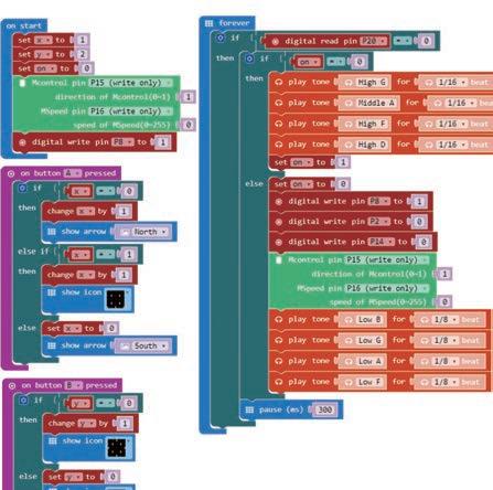
When we hear of remote-controls nowadays, everyone will assume it is some form of wireless Whentransmitter.abutton is pressed, the chip will automatically detect the message on the button for encoding, and then send the infrared signal through the IR diode; after the receiving device detects the optical signal, the receiver converts it into an electrical signal, and then follows the instruction to control the household appliance. Your micro:bit also has the function of a remote-control. Just write the desired control method in advance, then use the broadcast function.


112 Parts List 3 4 12 x2 23 x1 54 x4 57 x1 62 x2 69 x2 24 x2 27 x1 28 x15 1 x5 2 x3 14 x2 12 x2 13 x1 66 x2 59 x1 65 x2 58 x1 67


113 18 Motion Remote-ControlSensing Front View 5 7 6 59 58


114 Please refer to p.126 for tips on fixing the LED covers. Front View Sensor-a Sensor-b Light-a Light-b ABCDEFGHLight-bLight-a Sensor-aSensor-b GND5V 10 9 8 59 58


Done 115 18 Motion Remote-ControlSensing Smart Manual Web OperationModelServiceVideo
Program Example


116 1 2 3Evaluation AssembledModel ExperimentComplete CreationModel CreativityHands-on ExperimentHands-on Modify the model to make a remote control that can be used with oneObservehand.what happens when you move your micro:bit at different angles. How much do you have to move it? Is there a minimum? Try to control the direction of the snake on your display.
What type of jobs can't be replaced by artificial intelligence? Comparisons of tracks and wheels: Wheeled vehicles use a steering method to turn, they are faster, and the driving and suspension systems are of a relatively low cost. Because their characteristics are close to general civilian vehicles, personnel training and corrective maintenance are relatively easy; while tracked vehicles use a slipping method to turn, they can be rotated in situ, with high friction, low grounding pressure and high load capacity. It is not easily restricted by the road environment and can be used off-road.
Why are robots awesome? Because they also have a brain (AI)! However, like IQ, AI also has high and low scores in different categories. The quality of a robot depends on its AI. Big data is like books that AI reads into the brain. The more data, the richer the experience of the robot. Algorithms are like the nerves in a robot’s brain that specialize in digesting big data. When the sensors receive external information, or when the Internet of Things gets new data, algorithms are responsible for interpreting the signal and then reacting or producing a result. Algorithms are very important. Smart robots rely on smart AI, and smart AI must have good algorithms. Once you can write a program, you can create your own algorithm. AI not only defeats human brains in various chess / board games, but can also self-learn tasks that have not previously been given to it. There is also a trend of personalization. Nowadays, in Saudi Arabia and Japan, AI robots have obtained citizenship and residency rights, making movie scenes actually appear in real life.
DailyApplicationDaily
Brainstorming 117 19
Artificial Intelligence Scientific ApplicationMax Bot
The new world of AI (artificial intelligence) is coming. Nowadays, we often hear about robots, artificial intelligence, algorithms, and the Internet of Things. While everyone is still confused by most of these terms, the media has frequently reported that in the future, most human work will be done by robots.


118 Parts List Front side Front side 3 4 2 1 30mm 60mm 60mm 70mm70mm35mm 35mm 22 6 6 17 17 18 5 x2 42 x2 49 x1 54 x2 55 x4 56 x2 57 x1 62 x1 63 x2 64 x4 14 x2 15 x2 6 x4 16 x2 17 x2 11 x3 18 x4 12 x3 19 x2 21 x3 22 x2 24 x2 26 x2 31 x2 32 x2 33 x2 35 x2 41 x4 48 x23 1 x9 2 x1 66 x1 59 x1 65 x1 58 x1 67


119 19 Max Bot Please refer to p.126 for tips on connecting the belt. 11 10 7 8 6 22 22 ×148 ×249 9 ×2 21


120 Please refer to p.126 for tips on fixing the LED covers. How to adjust motors to vertical position Please make sure the hole on motors are vertical. Light-a Light-b Motor-aMotor-bMotor-c Light-bLight-aABCDEFGH Motor-aMotor-b Motor-c GND5V 15 13 14 16 12 18 57 57 59 58 21


Done ※ You may need a flashlight to run the model properly. 121 19 Max Bot Smart Manual Web OperationModelServiceVideo Program Example


122 1 2 3Evaluation AssembledModel ExperimentComplete CreationModel CreativityHands-on ExperimentHands-on Change the length of the belt and compare the differences in movement when use two 20T BELT and one 21T BELT, or when you use one 20T BELT and two 21T BELT. Record the differences. Modify the model & program to turn a crawler robot into a tracking robot.
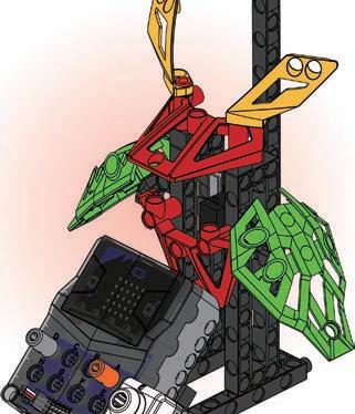
123 ReviewModel 20 Monograph 4 Please use the things you’ve learned so far to design a robotic arm that can be remotely controlled. 16. Telegraph Machine 18. Motion Sensing Remote Control 17. Robotic Arm 19. Max Bot


124 2 1 3 ConceptDesign Evaluation DesignModel CreationModel Winner! My Artwork
125 Appendix - Paper Card L6 Surveyor’s Measuring WheelPlease photocopy the picture to use.
126 How to replace the lampshade presspress How to connect the BELT OK Please photocopy the picture to use. (It is recommended that you use firm paper, or paper with card underneath.) L9 Microcomputer Plotter TIPS AND TRICKS:


MADE IN TAIWAN 2021 Genius Toy Taiwan Co., Ltd. ALL RIGHTS RESERVED R21#1269-3

