
PROBLEM 2.1
Chapter 2
STEADY STATE CONDUCTION
A plane wall, 7.5 cm thick, generates heat internally at the rate of 105 W/m3. One side of the wall is insulated, and the other side is exposed to an environment at 90°C. The convection heat transfer coefficient between the wall and the environment is 500 W/(m2 K). If the thermal conductivity of the wall is 12 W/(m K), calculate the maximum temperature in the wall.
GIVEN
Plane wall with internal heat generation
Thickness (L) = 7.5 cm = 0.075 m
Internal heat generation rate ( Gq ) = 105 W/m3
One side is insulated
Ambient temperature on the other side (T) = 90 °C
Convective heat transfer coefficient ( ch ) = 500 W/(m2 K)
Thermal conductivity (k) = 12 W/(m K)
FIND
The maximum temperature in the wall (Tmax)
ASSUMPTIONS
The heat loss through the insulation is negligible
The system has reached steady state
One dimensional conduction through the wall
SKETCH
SOLUTION
The one dimensional conduction equation, given in Equation (2.5), is
2 2 T x + Gq = c T t
For steady state, T t = 0 therefore
This is subject to the following boundary conditions
No heat loss through the insulation dT
= 0 at x = 0
Convection at the other surface
Integrating the conduction equation once
q k + C
C1 can be evaluated using the first boundary condition
Integrating again
The expression for T and its first derivative can be substituted into the second boundary condition to evaluate the constant C
Substituting this into the expression for T yields the temperature distribution in the wall
PROBLEM 2.2
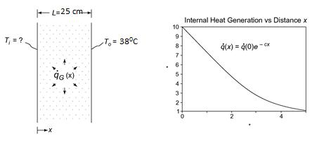
A small dam, which may be idealized by a large slab 1.2 m thick, is to be completely poured in a short period of time. The hydration of the concrete results in the equivalent of a distributed source of constant strength of 100 W/m3. If both dam surfaces are at 16°C, determine the maximum temperature to which the concrete will be subjected, assuming steady-state conditions. The thermal conductivity of the wet concrete may be taken as 0.84 W/(m K).
GIVEN
Large slab with internal heat generation
Internal heat generation rate ( Gq ) = 100 W/m3
Both surface temperatures (Ts) = 16°C
Thermal conductivity (k) = 0.84 W/(m K)
FIND
The maximum temperature (Tmax)
ASSUMPTIONS
Steady state conditions prevail
SKETCH
SOLUTION
The dam is symmetric. Therefore, x will be measured from the centerline of the dam. The equation for one dimensional conduction is given by Equation (2.5) k
For steady state, T t = 0 therefore k 2 2 dT dx + Gq = 0
This is subject to the following boundary conditions
1. By symmetry, dT/dx = 0 at x = o
2. T = Ts at x = L
Also note that for this problem Gq is a constant. Integrating the conduction equation
Integrating once again
dT
dx = –Gq k x + C1
The constant C1 can be evaluated using the first boundary condition
0 = –Gq k (0) + C1 C1 = 0
T = 2 Gq k x2 + C2
The constant C2 can be evaluated using the second boundary condition
Ts = 2 Gq k L2 + C2 C2 = Ts + 2 Gq k L2
Therefore, the temperature distribution in the dam is
T = Ts + 2 Gq k (L2 – x2)
The maximum temperature occurs at x = 0
Tmax = Ts + 2 Gq k (L2 – (0)2) = 16°C + 3100W/m 2[0.84W/(mK)] (0.6 m)2 = 37°C
COMMENTS
This problem is simplified significantly by choosing x = 0 at the centerline and taking advantage of the problem’s symmetry.
For a more complete analysis, the change in thermal conductivity with temperature and moisture content should be measured. The system could then be analyzed by numerical methods discussed in chapter 4
PROBLEM 2.3
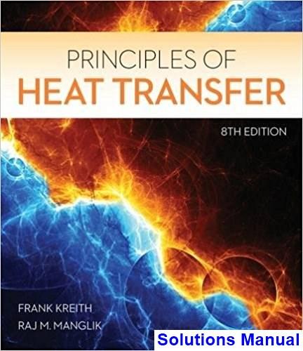
The shield of a nuclear reactor is idealized by a large 25 cm thick flat plate having a thermal conductivity of 3.5 W/(m K). Radiation from the interior of the reactor penetrates the shield and there produces heat generation that decreases exponentially from a value of 187.6 kW/ m3. at the inner surface to a value of 18.76 kW/m3 at a distance of 12.5 cm from the interior surface. If the exterior surface is kept at 38°C by forced convection, determine the temperature at the inner surface of the shield. Hint: First set up the differential equation for a system in which the heat generation rate varies according to q (x) = q (0)e –Cx .
GIVEN
Large flat plate with non-uniform internal heat generation
Thickness (L) = 25 cm=0.25 m
Thermal conductivity (k) = 3.5 W/(m K)
Exterior surface temperature (To) = 38°C
Heat generation is exponential with values of
187.6 kW/m3 at the inner surface
18.76 kW/m3 at 12.5 cm from the inner surface
FIND
The inner surface temperature (Ti)
ASSUMPTIONS
One dimensional, steady state conduction
The thermal conductivity is constant
No heat transfer at the inner surface of the shield
From the hint, the internal heat generation is
The one dimensional conduction equation is given by Equation (2.5)
PROBLEM 2.4
A plane wall 15 cm thick has a thermal conductivity given by the relation
k = 2.0 + 0.0005 T W/(m K) where T is in degrees Kelvin. If one surface of this wall is maintained at 150 °C and the other at 50 °C, determine the rate of heat transfer per square meter. Sketch the temperature distribution through the wall.
GIVEN
A plane wall
Thickness (L) = 15 cm = 0.15 m
Thermal conductivity (k) = 2.0 + 0.0005 T W/(m K) (with T in Kelvin)
Surface temperatures: Th = 150 °C Tc = 50 °C
FIND
(a) The rate of heat transfer per square meter (q/A)
(b) The temperature distribution through the wall
ASSUMPTIONS
The wall has reached steady state Conduction occurs in one dimension
SKETCH
SOLUTION
Simplifying Equation (2.2) for steady state conduction with no internal heat generation but allowing for the variation of thermal conductivity with temperature yields
ddT k
dxdx = 0
with boundary conditions: T = 423 K at x = 0
T = 323 K at x = 0.15 m
The rate of heat transfer does not vary with x
– k dT dx = q A = constant
– (2.0 + 0.0005T) dT = q A dx
Integrating
2.0T + 0.00025 T 2 = –q A x + C
The constant can be evaluated using the first boundary condition
2.0 (423) + 0.00025 (423)2 = C –q A (0) C = 890.7
(a) The rate of heat transfer can be evaluated using the second boundary condition:
2.0 (323) + 0.00025 (323)2 = 890.7 –q A (0.15 m) qk = 1457 W/m2
(b) Therefore, the temperature distribution is 0.00025 T 2 + 2.0 T = 890.7 – 1458 x
COMMENTS
Notice that although the temperature distribution is not linear due to the variation of the thermal conductivity with temperature, it is nearly linear because this variation is small compared to the value of the thermal conductivity.
If the variation of thermal conductivity with temperature had been neglected, the rate of heat transfer would have been 1333 W/m2, an error of 8.5%.
PROBLEM 2.5
Derive an expression for the temperature distribution in a plane wall in which there are uniformly distributed heat sources that vary according to the linear relation
Gq = wq [1 – (T – Tw)]
where qw is a constant equal to the heat generation per unit volume at the wall temperature Tw. Both sides of the plate are maintained at Tw and the plate thickness is 2L.
GIVEN
A plane wall with uniformly distributed heat sources as in the above equation
Both surface temperatures = Tw
Thickness = 2L
FIND
An expression for the temperature distribution
ASSUMPTIONS
Constant thermal conductivity (k)
SKETCH
The equation for one dimensional, steady state (dT/dt = 0) conduction from Equation (2.5) is
This is a second order, linear, nonhomogeneous differential equation with constant coefficients. Its solution is the addition of the homogeneous solution and a particular solution. The solution to the homogeneous equation
is determined by its characteristics equation. Substituting = ex and its derivatives into the homogeneous equation yields the characteristics equation 2 e
Therefore, the homogeneous solution has the form h = C1 cmx + C2 e –mx
A particular solution for this problem is simply a constant: = ao Substituting this into the differential equation 0 – m2 a
Therefore, the general solution is
With the boundary condition
PROBLEM 2.6
A plane wallof thickness 2L has internalheat sources whose strength varies according to
Gq = 0q cos (ax) where 0q is the heat generated per unit volume at the center of the wall (x = 0) and a is a constant. If both sides of the wall are maintained at a constant temperature of Tw, derive an expression for the total heat loss from the wall per unit surface area.
GIVEN
A plane wall with internal heat sources
Heat source strength: Gq = 0q cos (ax)
Wall surface temperatures = Tw
Wall thickness = 2L
FIND
An expression for the total heat loss per unit area (q/A) ASSUMPTIONS
Steady state conditions prevail
The thermal conductivity of the wall (k) is constant
One dimensional conduction within the wall
SKETCH SOLUTION
Equation (2.5) gives the equation for one dimensional conduction. For steady state, dT/dt = 0, therefore
0 cos()qax
With boundary conditions:
0 (by symmetry)
x = L (given)
Integrating the conduction equation once
Applying the first boundary condition yields: C1 = 0
The rate of heat transfer from one side of the wall is
The total rate of heat transfer is twice the rate of heat transfer from one side of the wall
An alternative method of solution for this problem involves recognizing that at steady state the rate of heat generation within the entire wall must equal the rate of heat transfer from the wall surfaces
COMMENTS
The heat loss can be determined by solving for the temperature distribution and then the rate of heat transfer or via the conservation of energy which allows us to equate the heat generation rate with the rate of heat loss.
PROBLEM 2.7
A very thin silicon chip is bonded to a 6-mm thick aluminum substrate by a 0.02-mm thick epoxy glue. Both surfaces of this chip-aluminum system are cooled by air at 250C, where the convective heat transfer coefficient of air flow is 100 W/(m2 K). If the heat dissipation per unit area from the chip is 104 W/m2 under steady state condition, draw the thermal circuit for the system and determine the operating temperature of the chip.
GIVEN
Silicon chip bonded to 6-mm thick aluminum substrate bye 0.02-mm thick epoxy glue
Air temperature(T∞)=250C
Convective heat transfer coefficient(h)=100 W/(m2 K)
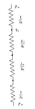
Heat dissipation from chip(q/A)= 104 W/m2
FIND
Draw thermal circuit of system
Operating temperature of the chip.
ASSUMPTIONS
1-Dimensional Steady state conditions prevail
Negligible heat loss from the sides
Isothermal chip
Negliglble radiation
SKETCH
SOLUTION
From the figure
Total heat transferred to the surrounding is sum of heat transferred from upper surface and lower surface. Thus
COMMENT
The heat transfer occurs on both sides through the chip to the surrounding. As there are both conductive and convective resistances on the lower side heat flow rate on the lower side will be less than that on the upper side which has only convective resistance.
PROBLEM 2.8
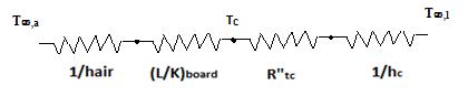
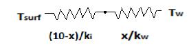
A thin, flat plate integrated circuit of 5 mm thickness is cooled on its upper surface by a dielectric liquid. The heat dissipation rate from the chip is 20,000 W/m2 and with the coolant flow at a free stream temperature of T∞,l =250C, the convective heat transfer coefficient between the chip surface and the liquid is 1000 W/(m2 K). On the lower surface, the chip is attached to a circuit board, where the thermal contact resistance between the chip and the board is 10-4 m2.K/W. The thermal conductivity of board material is 1.0 W/m. K, and its other surface ( away from the chip) is exposed to ambient air at T∞,a =200C where it is cooled by natural convection with the heat transfer coefficient of 30 W/(m2 K). (a) Determine the chip surface temperature under steady state condition for the described conditions. (b) If the maximum chip temperature is not to exceed 750C, determine maximum allowable heat flux that is generated by the chip. (c) A colleague suggests that in order to improve the cooling, you use a high conductivity bonding base at chip-board interface that would reduce the thermal contact resistance at the interface to 10-5 m2.K/W. Determine the consequent increase in the chip heat flux that can be sustained.
GIVEN
Heat dissipation rate (q )= 20,000 W/m2
Coolant free stream temp (T∞,l)= 250C
Ambientair temperature (T∞,a)= 200C
Heat transfer coefficient (h)= 1000 W/(m2 K)
Thermal contact resistance (R”tc) =10-4 m2.K/W
Maximumchip temperature=750C
FIND
(a) Chip surface temperature under steady state condition
(b) Maximum allowable heat flux generated by the chip
(c) Consequent increase in chip heat flux if high conductivity bonding is used.
ASSUMPTIONS
Steady state conditions prevail
The thermal conductivity of the wall (k) is constant
One dimensional conduction
Negligible radiation and thermal resistance between chip surface and the liquid.
SKETCH
The thermal circuit of problem is given by
SOLUTION
(a) A heat balance in the above problem gives
q = liquid q + air q
Substituting values from thermal circuits
(b)
for q from above equation, we get
55*26.01 W/m2
W/m2
4 W/m2
(c) Using the same equation as in (a), and changing only the value of thermal resistance, and using the value of Tc as 343 K, we get q=4.63*104 W/m2, which is a decrease in allowable heat dissipation of around 5126 W/m2
PROBLEM 2.9
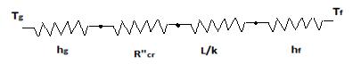
In a large chemical factory, hot gases at 2273 Kare cooled by a liquid at 373 Kwith gas side and liquid side convection heat transfer coefficients of 50 and 1000 W/(m2 K), respectively. The wallthat separates the gas and liquid streams is composed of 2-cm thick slab of stainless steelon the liquid side. There is a contact resistance between the oxide layer and the steelof 0.05 m2.K/W. Determine the rate of heat loss from hot gases through the composite wall to the liquid.
GIVEN
Hot gases at Tg=2273 K cooled by liquid at Tf=373 K
Convection heat transfer coefficients on gas side hg=50 W/(m2 K) and hf=100 W/(m2 K)
Wall of stainless steel of thickness(L)= 2 cm = 0.02 m
Contact resistance (Rcr”)= 0.05 m2.K/W
FIND
Rate of heat loss from hot gases through composite wall to liquid.
ASSUMPTIONS
1 Dimensional steady state heat transfer
Thermal conductivity remain constant.
Radiation is negligible.
SKETCH
PROPERTIES AND CONSTANTS
From Appendix 2, Table 10, Thermal conductivity of stainless steel (k) = 14.4 W/(m2 K)
Total resistance for the heat flow through the pipe is given by
Heatflux for the above resistance for given temperature difference is given by
PROBLEM 2.10
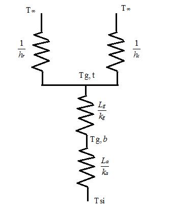
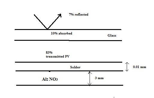
The conversion of solar energy into electric power by means of photovoltaic panels willbe an important part of the transition fromfossilfuels to sustainable energy resources. As described in detail in Principles of Sustainable Energy, a typicalPVpanel consists of a top layer of glass attached with a thin optically clear adhesive to a very thin layer of photoelectric material such as doped-silicon in which the incident solar irradiation is converted into electric energy. Experiments have shown that the solar to electric efficiency ƞ=0.55-0.001Tsilicon, where Tsilicon is the silicon temperature in K. In a typical installation where solar irradiation is G=700 W/m2, 7% is reflected from the top surface of the glass, 10% is absorbed by the glass, and 83% is transmitted to the photovoltaic active layer. A part of irradiation absorbed by photovoltaic materialis converted into heat and the remainder is converted into electric energy. The silicon layer is attached by a 0.01-mm thick layer of solder to a 3-mm thickaluminumnitride substrate as shown in the schemetic. Determine the electric power produced by this PVpanel, assuming the following properties for the pertinent materials: conductivity of the glass kg=1.4 W/(m K), conductivity of the adhesive ka=145 W/(m K), the emmisivity of the glass is 0.90, heat transfer coefficient fromthe top of the panel to the surrounding is 35 W/(m2K), and the surrounding air temperature is Tair=200C. The solar PVpanel is 5 m long and 1 mwide and is situated on the roof where the bottom is considered insulated. (Hint: Start by applying first law of thermodynamics to the photovoltaic-active layer and note that some of the irradiation willbe converted to electricity and some of it transmitted thermally).
GIVEN
Electric efficiency ƞ=0.55-0.001Tsilicon
Solar irradiation is G=700 W/m2
Thickness of solder(ts=0.01 mm
Al substrate thickness (tAl)=3 mm=0.003 m
Conductivityof the glass kg=1.4 W/(mK)
Conductivityof the adhesive ka=145 W/(mK)
Emissivityof the glass is 0.90
Heattransfer coefficientfromthe top of the panel to the surrounding(hc)= 35 W/(m2 K),
Surrounding air temperature is Tair=200C.
Solar PV panelarea= 5 m*1m
FIND
Electric power produced by the PV panel.
ASSUMPTIONS
1 Dimensional steady state heat transfer
Thermal conductivity remains constant.
SKETCH
PROPERTIES AND CONSTANTS
From Appendix 2, Table 10, Thermal conductivity of stainless steel (k) = 14.4 W/(m2 K)
SOLUTION
The energy which is not converted to electrical energy is transferred to the ambience through the adhesive and glass layer.
Also under steady state the heat transferred to the glass should be equal to total heat loss through glass to ambience.
Solving the above two equation in mathematical computational software (eg. Mathematica) we get
0.83*700*(1-0.55+0.001*306.6)*1*5 =2198 W=2.198 KW.
COMMENTS
The capacity of PV panel also depends on its cross sectional area. Thus more power can be generated if larger cross section of photovoltaic panels are used.
PROBLEM 2.11
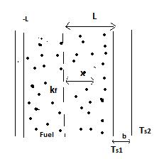
For the design of novel type of nuclear power plant, it is necessary to determine the temperature distribution in a large slab-type nuclear fuelelement. Volumetric heat is generated uniformly in the fuelelement at the rate of 2*107 W/m3. This slab fuelis insulated on one side, while on other side it is covered by a stainless steel cladding of 0.3 cm thickness. Heat is removed from the fuelslab by a liquid at 2000C that flows on the other side of the steelcladding with the convective heat transfer coefficient of 10,000 W/(m2 K). Determine the maximum temperature in the fuelelement and sketch the temperature distribution.
GIVEN
Volumetric heat generated (q )=2*107 W/m2
Stainless steel cladding thickness (y)= 0.3 cm = 0.003 m
Coolant liquid temperature (T∞)= 2000C
Heat transfer coefficient(h)= 1000 W/(m2 K)
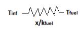
Fuel element thickness (x)=1.5 cm = 0.015 m
FIND
Maximum temperature in fuel element Sketch temperature distribution.
ASSUMPTIONS
1 Dimensional steady state heat transfer
Constant properties.
Uniform heat generation.
Negligible contact resistance between surfaces.
SKETCH
PROPERTIES AND CONSTANTS
From Appendix 2, Table 10, Thermal conductivity of stainless steel (k) = 14.4 W/(m2 K) SOLUTION
Heat transfer equation in 1 dimension with steady state and uniform heat generation is given by 2
where x varies from –L to L
Integrating twice we get
dTq xC dxk and
1 f
q TxCxC k where C1 and C2 are constants.
2 12 2 f
Applying boundary conditions
1. The wall is insulated at the end thus q (x=-L)=0 ( which implies dT dx =0)
dTq LC dxk
1 f
12 s ss k TT b
q convection equation is
122 s sss k TThTT b
T(L)=Ts1= (2)(2) s
The differential equation at x=L gives
Tx=L= 22 2 2 ff qqLLC kk
bL TqL khk
Substituting C1 and C2 in the integrated differential equation we get
2
223 22 ffsf TxLxTqLqqbL kkkhk
Applying this condition in differential equation above we get
Substituting
PROBLEM 2.12
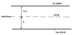
Nomads in the desert make ice by exposing a thin water layer to cold air during the night. The icing or freezing of thin layers of water is often also referred to as ice making by nocturnal ( or night time ) cooling, where the surface temperature of water is lowered considerably by radioactive and convective cooling, and it had been practiced extensively in ancient India. To model this process and evaluate the conduction process in water layer, consider a 5-mm thick horizontal layer gets cooled such that its top surface is at temperature of50C. After a while the water begins to freeze at top surface and the ice front expands downwards through the water layer. Determine the location of solid liquid(ice-water) interface if the bottom surface temperature of the liquid water is at 30C. State your assumptions for the model and calculations.
GIVEN
Thickness of the layer(t)= 5 mm
Surface temperature (Ts)= -50C=268 K
Water temperature(Tw)= 30C= 276 K
FIND
Location of solid liquid interface .
ASSUMPTIONS
1 Dimensional steady state heat transfer
Constant properties throughout time
Negligible radiation
Negligible convection by liquid.
SKETCH
PROPERTIES AND CONSTANTS
From Appendix 2, Table 10,
For water at 273 K, kw=0.569 W/mK
For ice at 273 K, ki=1.88 W/mK
SOLUTION
If x is the distance of solid liquid interface from liquid surface, the energy balance over the interface gives *(273)*(273) 5 wwis kTkT xx => 0.569*(276273)1.88*(273268) 5 xx
Solving for x we get
1.707(5-x) = 9.4 x => x=0.77 mm
Thus the interface is at distance of 0.77 mm from liquid surface or 4.23 mm from ice surface.
STEADY STATE CONDUCTION IN CYLINDERS
PROBLEM 2.13
The heat conduction equation in cylindrical coordinates is
(a) Simplify this equation by eliminating terms equal to zero for the case of steady-state heat flow without sources or sinks around a right-angle corner such as the one in the accompanying sketch. It may be assumed that the corner extends to infinity in the direction perpendicular to the page. (b) Solve the resulting equation for the temperature distribution by substituting the boundary condition. (c) Determine the rate of heat flow from T1 to T2. Assume k = 1 W/(m K) and unit depth .
GIVEN
Steady state conditions
Right-angle corner as shown below
No sources or sinks
Thermal conductivity (k) = 1 W/(m K)
FIND
(a) Simplified heat conduction equation
(b) Solution for the temperature distribution
(c) Rate of heat flow from T1 to T2
ASSUMPTIONS
Corner extends to infinity perpendicular to the paper
No heat transfer in the z direction
Heat transfer through the insulation is negligible
SKETCH
The boundaries of the region are given by
Assuming there is no heat transfer through the insulation, the boundary condition is T r = 0 at r = 1 m
T r = 0 at r = 2 m
T1 = 100°C at = 0
T2 = 0°C at = 2
(a) The conduction equation is simplified by the following
= 0 over both boundaries,
= 0 throughout the region
(Maximum principle); therefore,
Substituting these simplifications into the conduction equation
= 0 throughout the region also.
(b) Integrating twice T = c1 + c2
The boundary condition can be used to evaluate the constants At
Therefore, the temperature distribution is
T() = 100 –200C °C
(c) Consider a slice of the corner as follow
The heat transfer flux through the shaded element in the direction is q
In the limit as 0, q= – k dT rd
Multiplying by the surface area drdz and integrating along the radius q = 1
or r
or r qdrdz = 200°Ck 1
dr r = 200°Ck ln
q = 200°Ck [1 W/(m K)] ln(2 m/1 m) = 44.1 W/m 44.1W per meter in the z direction
COMMENTS
Due to the boundary conditions, the heat flux direction is normal to radial lines.
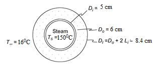
PROBLEM 2.14
Calculate the rate of heat loss per foot and the thermal resistance for a 15 cm schedule 40 steel pipe covered with a 7.5 cm thick layer of 85% magnesia. Superheated steam at 150°C flows inside the pipe [ ch = 170 W/(m2 K)] and still air at 16°C is on the outside [ ch = 30 W/(m2 K)].
GIVEN
A 6 in. standard steel pipe covered with 85% magnesia
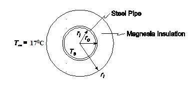
Magnesia thickness = 15 cm=0.15 m
Superheated steam at Ts= 150°C flows inside the pipe
Surrounding air temperature (T) = 17°C
Heat transfer coefficients
Inside ( cih ) = 170 W/(m2 K)
Outside ( coh ) = 30 W/(m2 K)
FIND
(a) The thermal resistance (R)
(b) The rate of heat loss per foot (q/L)
ASSUMPTIONS
Constant thermal conductivity
The pipe is made of 1% carbon steel
SKETCH
PROPERTIES AND CONSTANTS
From Appendix 2, Tables 10, 11, and 41
For a 6 in. schedule 40 pipe
Inside diameter (Di) = 6.065 in.=0.154 m
Outside diameter (Do) = 6.625 in.=0.1683 m
Thermal Conductivities
85% Magnesia (kI) = 0.059 W/(m K) at 20°C
1% Carbon steel (ks) = 43 W/(m K) at 20°C
SOLUTION
The thermal circuit for the insulated pipe is shown below
(a) The values of the individual resistances can be calculated using Equations (1.14) and (2.39)
(b) The rate of heat transfer is given by
COMMENTS
Note that almost all of the thermal resistance is due to the insulation and that the thermal resistance of the steel pipe is negligible.
PROBLEM 2.15
Suppose that a pipe carrying a hot fluid with an external temperature of Ti and outer radius ri is to be insulated with an insulation material of thermal conductivity k and outer radius ro. Show that if the convective heat transfer coefficient on the outside of the insulation is h and the environmental temperature is T, the addition of insulation can actually increases the rate of heat loss if ro < k /h and that maximum heat loss occurs when ro = k/h . This radius, rc, is often called the critical radius.
GIVEN
An insulated pipe
External temperature of the pipe = Ti
Outer radius of the pipe = ri
Outer radius of insulation = ro
Thermal conductivity = k
Ambient temperature = T
Convective heat transfer coefficient = h
FIND
Show that
(a) The insulation can increase the heat loss if ro < k/h
(b) Maximum heat loss occurs when ro = k/h
ASSUMPTIONS
The system has reached steady state
The thermal conductivity does not vary appreciably with temperature
Conduction occurs in the radial direction only
SKETCH
SOLUTION
Radial conduction for a cylinder of length L is given by Equation (2.37)
Convection from the outer surface of the cylinder is given by Equation (1.10)
The outer wall temperature, To, is an unknown and must be eliminated from the equation Solving
Substituting this into the convection equation
Examining the above equation, the heat transfer rate is a maximum when the term
is a minimum, which occurs when its differential with respect to ro is zero
which is greater than zero at ro = k/h, therefore ro = k/h is a true minimum and the maximum heat loss occurs when the diameter is ro = k/h. Adding insulation to a pipe with a radius less than k/h will increase the heat loss until the radius of k/h is reached.
COMMENTS
A more detailed solution taking into account the dependence of hc on the temperature has been obtained by Sparrow and Kang, Int. J. Heat Mass Transf., 28: 2049–2060, 1985.
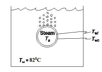
PROBLEM 2.16
A solution with a boiling point of 82°C boils on the outside of a 2.5 cm tube with a No. 14 BWG gauge wall. On the inside of the tube flows saturated steam at 40 kPa(abs). The convection heat transfer coefficients are 8.5 kW/(m2 K) on the steam side and 6.2 kW/(m2 K) on the exterior surface. Calculate the increase in the rate of heat transfer if a copper tube is used instead of a steel tube.
GIVEN
Tube with saturated steam on the inside and solution boiling at 82°C outside
Tube specification: 1 in. No. 14 BWG gauge wall
Saturated steam in the pipe is at 40 kPa(abs)
Convective heat transfer coefficients
Steam side ( cih ) : 8.5 kW/(m2 K)
Exterior surface ( coh ) : 6.2 kW/(m2 K)
FIND
The increase in the rate of heat transfer for a copper over a steel tube ASSUMPTIONS
The system is in steady state
Constant thermal conductivities
SKETCH
PROPERTIES AND CONSTANTS:
From Appendix 2, Tables 10, 12, 13 and 42
Temperature of saturated steam at 60 psia (Ts) = 144°C
Thermal conductivities
Copper (kc) = 391 W/(m K) at 127°C
1% Carbon steel (ks) = 43 W/(m K) at 20°C
Tube inside diameter (Di) = 0.0212 m
SOLUTION
The thermal circuit for the tube is shown below
The increase in the rate of heat transfer per unit length with the copper tube is
COMMENTS
The choice of tubing material is significant in this case because the convective heat transfer resistances are small making the conductive resistant a significant portion of the overall thermal resistance.
PROBLEM 2.17
Steam having a quality of 98% at a pressure of 1.37 105 N/m2 is flowing at a velocity of 1 m/s through a steel pipe of 2.7 cm OD and 2.1 cm ID. The heat transfer coefficient at the inner surface, where condensation occurs, is 567 W/(m2 K). A dirt film at the inner surface adds a unit thermal resistance of 0.18 (m2 K)/W. Estimate the rate of heat loss per meter length of pipe if; (a) the pipe is bare, (b) the pipe is covered with a 5 cm layer of 85% magnesia insulation. For both cases assume that the convective heat transfer coefficient at the outer surface is 11 W/(m2 K) and that the environmental temperature is 21°C. Also estimate the quality of the steam after a 3-m length of pipe in both cases.
GIVEN
A steel pipe with steam condensing on the inside
Diameters
Outside (Do) = 2.7 cm = 0.027 m
Inside (Di) = 2.1 cm = 0.021 m
Velocity of the steam (V) = 1 m/s
Initial steam quality (Xi) = 98%
Steam pressure = 1.37 105 N/m2
Heat transfer coefficients
Inside (hci) = 567 W/(m2 K)
Outside (hco) = 11 W/(m2 K)
Thermal resistance of dirt film on inside surface (Rf) = 0.18 (m2 K)/W
Ambient temperature (T) = 21°C
FIND
The heat loss per meter (q/L) and the change in the quality of the steam per 3 m length for
(a) A bare pipe
(b) A pipe insulated with 85% Magnesia: thickness (Li) = 0.05 m
ASSUMPTIONS
Steady state conditions exist
Constant thermal conductivity
Steel is 1% carbon steel
Radiative heat transfer from the pipe is negligible
Neglect the pressure drop of the steam SKETCH
PROPERTIES AND CONSTANTS
From Appendix 2, Tables 10, 11, and 13
The thermal conductivities are:
1% carbon steel (ks) = 43 W/(m K) at 20°C
85% Magnesia (ki) = 0.059 W/(m K) at 20°C
5 N/m2:
Temperature (Tst) = 107°C
Heat of vaporization (hfg) = 2237 kJ/kg Specific volume (
) = 1.39 m3/kg
(a) The thermal circuit for the uninsulated pipe is shown below
Evaluating the individual resistances
The rate of heat transfer through the pipe is
= 22.5 W/m
The total rate of transfer of a three meter section of the pipe is
q = 22.5 W/m (3 m) = 67.4 W
The mass flow rate of the steam in the pipe is sm = i s
AV = 2 4 i s
DV = 2 3 (0.021m)(1m/s) 4(1.39m/kg)(1kg/1000g) = 0.249 g/s
The mass rate of steam condensed in a 3 meter section of the pipe is equal to the rate of heat transfer divided by the heat of vaporization of the steam
cm = fg
q h = 67.4W 2237J/g(Ws/J) = 0.030 g/s
The quality of the saturated steam is the fraction of the steam which is vapor. The quality of the steam after a 3 meter section, therefore, is Xi = (original vapor mass)(mass of vapor condensed) total mass of steam = isc s
Xmm m
Xi = 0.98(0.249g/s)0.030g/s 0.249g/s = 0.86 = 86%
The quality of the steam changed by 12%.
The thermal circuit for the pipe with insulation is shown below
The convective resistance on the outside of the pipe is different than that in part (a) because it is based on the outer area of the insulation
in 3
The quality of the steam after 3 meters of pipe is
The change in the quality of the steam is 6%.
COMMENTS
Notice that the resistance of the steel pipe and the convective resistance on the inside of the pipe are negligible compared to the other resistances.
The resistance of the dirt film is the dominant resistance for the uninsulated pipe.
PROBLEM 2.18
Estimate the rate of heat loss per unit length from a 5 cm ID, 6 cm OD steel pipe covered with high temperature insulation having a thermal conductivity of 0.11 W/(m K) and a thickness of 1.2 cm. Steam flows in the pipe. It has a quality of 99% and is at 150°C. The unit thermal resistance at the inner wall is 0.0026 (m2 K)/W, the heat transfer coefficient at the outer surface is 17 W/(m2 K), and the ambient temperature is 16°C.
GIVEN
Insulated, steam filled steel pipe
Diameters
ID of pipe (Di) = 5 cm=0.05 m
OD of pipe (Do) = 6 cm=0.06 m
Thickness of insulation (Li) = 1.2 cm=0.012 m
Steam quality = 99%
Steam temperature (Ts) = 150°C
Unit thermal resistance at inner wall (A Ri) = 0.026 (m2 K)/W
Heat transfer coefficient at outer wall (ho) = 17 W/(m2 K)
Ambient temperature (T ) = 16°C
Thermal conductivity of the insulation (kI) = 0.11 W/(m K)
FIND
Rate of heat loss per unit length (q/L)
ASSUMPTIONS
1% carbon steel
Constant thermal conductivities
Steady state conditions
SKETCH
PROPERTIES AND CONSTANTS
From Appendix 2, Table 10
The thermal conductivity of 1% carbon steel (ks) = 43 W/(m2 °K) at 20 °C
SOLUTION
The outer diameter of the insulation (DI) = 6 cm + 2(1.2 cm) = 8.4 cm
The thermal circuit of the insulated pipe is shown below
The values of the individual resistances are
PROBLEM 2.19
The rate of heat flow per unit length q/L through a hollow cylinder of inside radius ri and outside radius ro is
q/L = ( A k T)/(ro – ri) where A = 2 (ro – ri)/ln(ro/ri). Determine the per cent error in the rate of heat flow if the arithmetic mean area (ro + ri) is used instead of the logarithmic mean area A for ratios of outside to inside diameters (Do/Di) of 1.5, 2.0, and 3.0. Plot the results.
GIVEN
A hollow cylinder
Inside radius = ri
Outside radius = ro
Heat flow per unit length as given above
FIND
(a) Per cent error in the rate of heat flow if the arithmetic rather than the logarithmic mean area is used for ratios of outside to inside diameters of 1.5, 2.0, and 3.0.
(b) Plot the results
ASSUMPTIONS
Radial conduction only
Constant thermal conductivity
Steady state prevails
The rate of heat transfer per unit length using the logarithmic mean area is
The rate of heat transfer per unit length using the arithmetic mean area is
The percent errors for the other diameter ratios can be calculated in a similar manner with the following results
COMMENTS
For diameter ratios less than 2, use of the arithmetic mean area will not introduce more than a 4% error.
PROBLEM 2.20
A 2.5-cm-OD, 2-cm-ID copper pipe carries liquid oxygen to the storage site of a space shuttle at –183°C and 0.04 m3/min. The ambient air is at 21°C and has a dew point of 10°C. How much insulation with a thermal conductivity of 0.02 W/(m K) is needed to prevent condensation on the exterior of the insulation if hc + hr = 17 W/(m2 K) on the outside?
GIVEN
Insulated copper pipe carrying liquid oxygen
Inside diameter (Di) = 2 cm = 0.02 m
Outside diameter (Do) = 2.5 cm = 0.025 m
LOX temperature (Tox) = – 183°C
LOX flow rate (mox) = 0.04 m3/min
Thermal conductivity of insulation (ki) = 0.02 W/(m K)
Exterior heat transfer coefficients (ho = hc + hr) = 17 W/(m2 K)
Ambient air temperature (T ) = 21°C
Ambient air dew point (Tdp) = 10°C
FIND
Thickness of insulation (L) needed to prevent condensation
ASSUMPTIONS
Steady-state conditions have been reached
The thermal conductivity of the insulation does not vary appreciably with temperature
Radial conduction only
The thermal resistance between the inner surface of the pipe and the liquid oxygen is negligible, therefore Twi =
SKETCH
PROPERTIES AND CONSTANTS
From Appendix 2, Table 12, thermal conductivity of copper (kc) = 401 W/(m K) at 0°C
SOLUTION
The thermal circuit for the pipe is shown below
The rate of heat transfer from the pipe is
COMMENTS
Note that the thermal resistance of the copper pipe is negligible compared to that of the insulation.
PROBLEM 2.21
A salesperson for insulation material claims that insulating exposed steam pipes in the basement of a large hotel will be cost effective. Suppose saturated steam at 5.7 bars flows through a 30-cmOD steel pipe with a 3 cm wall thickness. The pipe is surrounded by air at 20°C. The convective heat transfer coefficient on the outer surface of the pipe is estimated to be 25 W/(m2 K). The cost of generating steam is estimated to be $5 per 109 J and the salesman offers to install a 5 cm thick layer of 85% magnesia insulation on the pipes for $200/m or a 10-cm-thick layer for $300/m. Estimate the payback time for these two alternatives assuming that the steam line operates all year long and make a recommendation to the hotel owner. Assume that the surface of the pipe as well as the insulation have a low emissivity and radiative heat transfer is negligible.
GIVEN
Steam pipe in a hotel basement
Pipe outside diameter (Do) = 30 cm = 0.3 m
Pipe wall thickness (Ls) = 3 cm = 0.03 m
Surrounding air temperature (T) = 20°C
Convective heat transfer coefficient (hc) = 25 W/(m2 K)
Cost of steam = $5/109 J
Insulation is 85% magnesia
FIND
Payback time for
(a) Insulation thickness (LIa) = 5 cm = 0.05 m; Cost = $200/m
(b) Insulation thickness (LIb) = 10 cm = 0.10 m; Cost = $300/m
Make a recommendation to the hotel owner.
ASSUMPTIONS
The pipe and insulation are black (= 1.0)
The convective resistance on the inside of the pipe is negligible, therefore the inside pipe surface temperature is equal to the steam temperature
The pipe is made of 1% carbon steel
Constant thermal conductivities
SKETCH
PROPERTIES AND CONSTANTS
From Appendix 1, Table 5: The Stefan-Boltzmann constant (
From Appendix 2, Table 10 and 11
Thermal conductivities: 1% Carbon Steel (ks) = 43 W/(m K) at 20°C
85% Magnesia (kI) = 0.059 W/(m K) at 20°C
8 W/(m2 K4)