
George Lee portfolio G L
1 2 3 4


ProfessionalSelectedProjectsWork 5 6 1 | Shoreline DADU 2 | Portland MCM Remodel 3 | Pine Lake Middle School 4 | 10th St Condominiums 5 | Potrero Hill Remodel 6 | Glen Park Remodel 50401041628


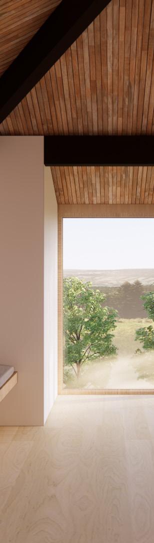
4 LEEGEORGE @R15UP71/4"=9'-1" 03D D02 D01103101 102 1/4"12 28'-0" 4'-7CLR3'-6"1/2"7'-4" 20'-8" 1/2"15'-11/2"7'-75'-3"28'-0"4'-0" 7'-4" 19'-7 1/2"32'-0" 3'-4 1/2" 3/4"8'-66'-0" A301 2 A301 SOFFIT SHOWNBEAMSHOWNABOVEDASHEDABOVEDASHED BENCH( 12 W1 W1 W1 W1 W2 W2 W3 SLOPE GARAGE SLAB TO DRAIN TROWEL FINISH & SEALED CONC SHEET FLOORINGLINOLEUMATENTRY GARAGE 645 SF STAIR 88 SF ENTRY 48 SF STORAGE B C D DOWN @R1571/4"9'-1" 202 203201204205 R WD 1 A301 A301 28'-0" 32'-0"1/2"15'-81/2"13'-33'-0" 3'-0" 28'-0"CLR 16'-2 1/2" 11'-9 1/2" 1/2"13'-310"5'-1"11'-5"7'-5 3/4" 19'-5 1/4" 13'-3 3/4" 1/2" 13'-3 3/4" 5'-5" 3'-8 1/2" 8'-6" 9'-10" 8'-6" CLR3'-6" 08100911050405 0606 07C0707B 0303 02 01B 01A (ABOVE)(ABOVE)(ABOVE)(ABOVE)(ABOVE) (ABOVE) (ABOVE) (ABOVE) W1 W1 W1 W1 W3 W3 W3 W3 W3 W3 LIVINGSTRAND-WOVENBAMBOOFLOORINGTHROUGHOUTSPACES&BEDROOMS SHEET BATHROOMSFLOORINGLINOLEUMATTYP ECONOMY GRADE KITCHEN IKEA OR PRICINGIKEA-TYPE HTRHW BEDRM 150 SF BEDRM 150 SF BATH 43 SF BATH 1 43 SF LIVING/DINING/KITCHEN 306 SF HALL 38 SF A B C 4312 1/4"1'-71/4"2'-111/2"13'-33'-0"3'-6"4"3'-6"4"3'-6"122.5 29'-0" 35'-0" OVHNG6" 1'-0" OVHNG 2'-0" OVHNG STANDING SEAM MTL ROOF SOLAR READY FOR FUTURE PV ARRAY MTL GUTTER AND ROUND DSSHOWNWALLSMTLSTANDINGSCHEDULESKYLIGHTCURB-MOUNTEDPERSEAMROOFPNLSBELOWDASHED SK01 MTL DASHEDPERROOFOVERCANOPYPORCHBEAMSTRUCTBELOW B C D 1/4"12 28'-0" 1/2"32'-0 7'-4" 20'-8" 1/2"28'-04'-0" WALLS PERWALLWALLCONCSHOWNABOVEDASHEDSTEMRETAINING&FOOTINGSTRUCT CONC S.O.G. PER CONCSTRUCTSTEM WALL & FOOTING PER STRUCT., TYP CONC FOOTING & WD POST FOR DECK PORCH PERWDSTRUCTDECK PORCH ABOVE SLABSLOPEDASHEDSHOWNGARAGETODRAINR-10NSULATIONRIGID AT PERIMETER FOOTINGSPACECONDITIONEDFORONLYINTERIORSIDEOF A301 2 A301 B C D N SCALE 1/4" 1'-0" 1 LEVEL 1 (GARAGE) SCALE 1/4" 1'-0" 3 LEVEL 2 (ADU) SCALE 1/4" 1'-0" 4 ROOF PLAN SCALE 1/4" 1'-0" 2 FOUNDATION PLAN Contributions: Architect (design and production) A new construction 900 SF accessory dwelling unit above a garage and workshop. The design features an efficient open plan, generously sized windows and vaulted ceilings to create a light-filled and modern living space. The simple form, clear-span garage, and shed roof take advantage of Structural Insulated Panels to reduce construction labor and provide an building envelope with increased insulation and air-tightness. The project targets Built Green 4-Star to meet the Shoreline’s Deep Green Incentive Program. PROFESSIONAL PROJECT 1 Shoreline DADU Shoreline, WA | 2021 | Personal Commissioned Project Phases: SD-DD-CD


6 LEEGEORGE DADUSHORELINE


Working in collaboration with the project’s structural engineer, the design is optimized for simplified construction using Structural Insulated Panels.
8 LEEGEORGE DADUSHORELINE

GSEducationalVersion SCALE 1 1/2"= 1'-0" 3 ENTRY WALL SECTION SCALE 1 1/2"= 1'-0" 4 GARAGE DOOR WALL SECTION SCALE 1 1/2"= 1'-0" 1 TYPICAL WALL SECTION SCALE 1 1/2"= 1'-0" 2 SKYLIGHT & SOFFIT WALL SECTION METAL PANEL ROOF SHEET METAL BOX GUTTER 5/4X12 FASCIA CLEAT BUTYL, & TAPE FASTENER PER MANUF WINDOW PER SCHEDULE WRB 11 7/8 X 6 1/2 INSULATED SIP HEADER PER STRUCT. AND ANDBEVELMANUF.REQUIREMENTSBLOCKPERSTRUCTMANUFREQUIREMENTS 10-1/4 SIP ROOF PANEL RAINSCREEN SIDING FACTORY STANDARD SIP ELECTRICAL CHASE PAINTED WALL BASE TRIM FINISH FLOORING PER PLYWOODSCHEDULESUBFLOOR PER STRUCT BEAM PER STRUCT 10-1/4" SIP FLOOR PANEL METAL HEAD FLASHING METAL SILL FLASHING SOFFIT PANEL METAL DRIP EDGE FLASHING SHEATHING AS REQUIRED FOR WRB PAINTED TRIM DOOR PER SCHEDULE DOOR SILL PER MANUF BEAM HEADER PER STRUCTMETALDRIPEDGEFLASHING5/4JAMBLINERSECTIONALGARAGEDOORPERSCHEDULE METAL PANEL ROOFCURBWRB MOUNTED SKYLIGHT PER SCHEDULE (CURB OUTSIDE DIMENSION 46-1/2" X 46-1/2") FLASHING PER METAL PANEL MANUF 2X CURB LAP WRB UP AND OVER CURB SEAL TOP OF CURB PER MANUF REQUIREMENTS LET-IN 2X HEADER PER ANDREQUIREMENTSMANUFSTRUCTPAINTEDPLYWOODLINERPANELFORSKYLIGHTSHAFTINTERIORTRANSOMWINDOWABOVEINTERIORDOORBEAMPERSTRUCTDROPPEDSOFFIT AND FRAMING FOR HORIZONTAL SERVICE CAVITY FOR MEP ROUTING EXPOSED BEAM PER STRUCT5/8 TYPE X GYPSUM WALL BOARD THROUGHOUT GARAGE BEVEL BLOCK AS REQUIRED CONCRETE FOUNDATION WALL WITH FULL BEARING AND FOOTING PER STRUCT GRAVEL DRAINAGE LAYER PER 10GRADECONCRETESTRUCTSLAB-ON-PERSTRUCTMILVAPORBARRIER 6-1/2" SIP WALL PANELWRB ANCHOR BOLTS HOLD-DOWNS, & STRAPPING PER STRUCT 2X TREATED SILL PLATE CUT TO WIDTH OF PANEL FOR FULL BEARING PER MANUFMETALREQUIREMENTSBASEFLASHING RUBBER BASE TYP IN GARAGE SILL SEALER REFERENCE SIP MANUF DETAIL: PBS 103 PANEL FOUNDATION CONNECTION REFERENCE SIP MANUF DETAIL: PBS-111 PLATFORM FRAMING MASTIC AND SEALANT BETWEEN PLATE WALL PANEL AND ALL OTHER COMPONENTS PER MANUF REQUIREMENTS PAINTED WALL BASE TRIM FINISH FLOORING PER SCHEDULE PLYWOOD SUBFLOOR PER STRUCT 10-1/4" SIP FLOOR PANEL FASTENERS PER MANUF REQUIREMENTS REFERENCE SIP MANUF DETAIL PBS 310 ROOF FLOOR OPENINGS REFERENCE SIP MANUF DETAIL: PBS 303 BEVELED PANEL WALL ROOF CONNECTION REFERENCE SIP MANUF DETAIL: PBS 314 EAVE DETAILS 2X PLATE RIPPED TO WIDTH OF PANEL PER STRUCT AND MANUF REQUIREMENTS METAL PANEL ROOF 5/4X12 FASCIA CLEAT BUTYL & TAPE FASTENER PER MANUF 10WRB-1/4" SIP ROOF PANEL SOFFIT PANEL METAL PEAK FLASHING PER REQUIREMENTSMANUF5%SLOPE MIN AWAY FROM BUILDING PER CODE REQUIREMENTS SHEATHING PER GARAGESTRUCT SLAB SLOPED TO DRAIN PER PLANS CONCRETE STEM WALL FOUNDATION BEYONDR-10 INSULATIONPERIMETERPER PLANS AND WSEC REQUIREMENTS MDO TRIM PANEL, PAINTED FREE DRAINING GRAVEL NO FINES IN FILTER 4FABRIC"PERFORATED PIPE FOUNDATION DRAIN WITH FILTER FABRIC
10 LEEGEORGE
Contributions: Project Designer/Project Manager/BIM Documentation/Visualizations
PROFESSIONAL PROJECT 2 Portland Midcentury Modern Remodel Portland, OR | Designed 2021 | SHED Architecture & Design Phases: SD-DD-CD
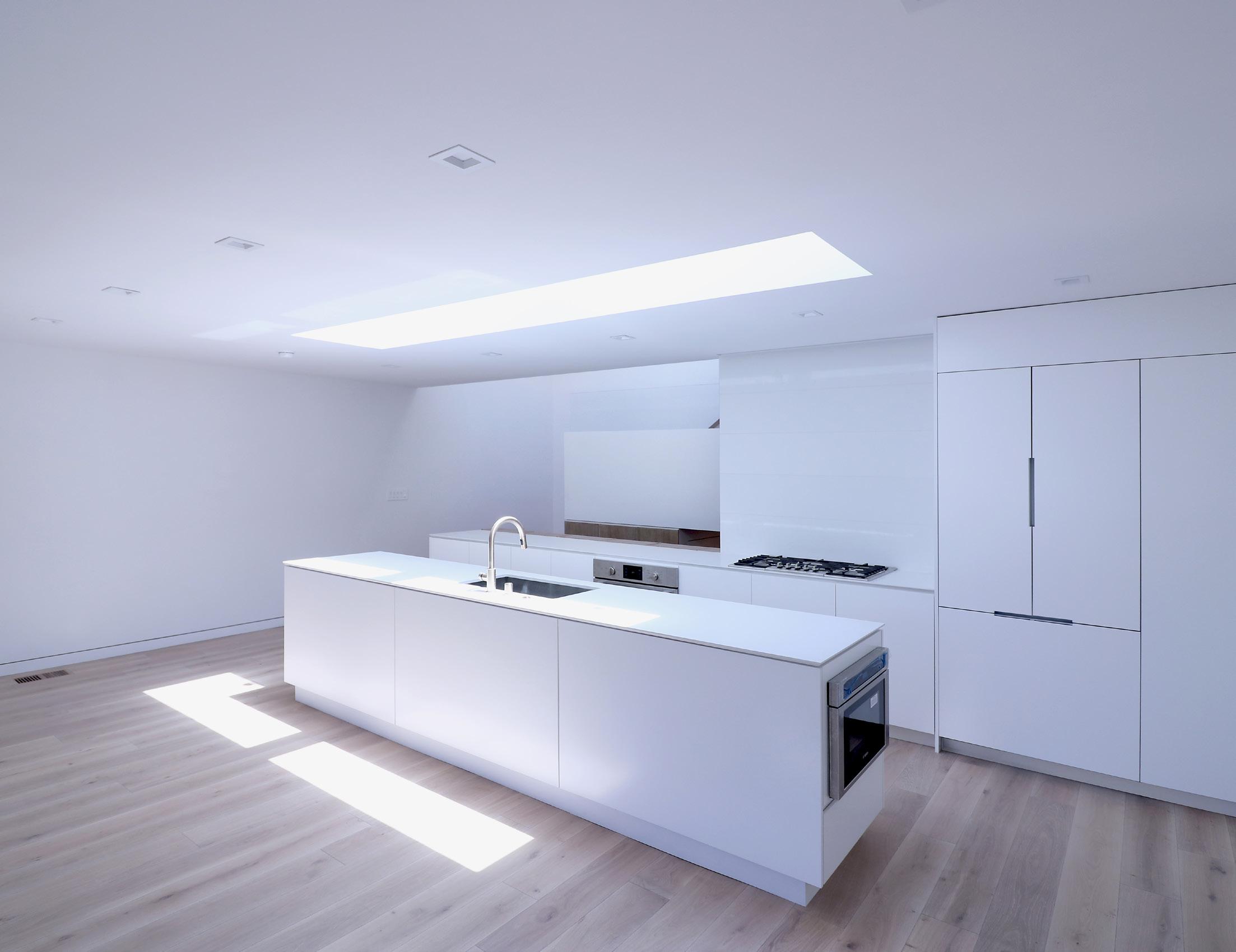
This extensive renovation of a 1962 midcentury modern house by Saul Zaik reconfigures the entire house to amplify abundant natural light and enhance relationships to the forested site in every space. Working under direction of the design principal, I assisted in the development and coordination of all project documents from the initial client meeting through design development, permitting, and construction documentation. Throughout the project I was solely responsible for all Archicad BIM work as well as a design Sketchup model for renderings.

The design emphasizes fluid open-plan living spaces throughout the upper floor by removing an existing mezzanine platform and partial ceilings to showcase the original nail-laminated roof deck. Slatted wooden screen walls and interior relites allow light from the central skylight to enter the primary bedroom and bathroom suite. A unique roof support structure consisting of an upper tension ring, lower collar beams, and hip beams are also exposed throughout. The project is currently under construction.

12 LEEGEORGE REMODELMCMPORTLAND ROOM XXX sq ft X" X A XXX X A XXX XXX XXX PLAN NOTES: ALL DIMS ARE TO FACE OF FRAMING OR FACE OF CONCRETE BRICK U N O ALL INDICATED ALIGNMENTS ARE TO O FINISH WINDOW OPENING DIMENSIONS ARE MEASURED FROM THE ROUGH OPENING REFER TO WINDOW DOOR SCHEDULES FOR ADDITIONAL INFO REFER TO STRUCTURAL FOR FRAMING INFO ALL FLOOR TRANSITIONS SHALL BE AT CENTER OF DOOR U N O REFER TO ASSEMBLIES FOR WALL THICKNESSES AND FRAMING DIMENSIONS REFER TO PLUMBING SHEETS FOR FLOOR DRAIN LOCATIONS ALL CEILING EXPOSED H T STRUCTURE U N O 1 2 3 4 5 6 7 8 WALL SECTION TAG ELEVATION TAG NEW DOOR TAG EXISTING DOOR TAG ROOM TAG LEVEL DIMENSION EXISTING MASONRY WALL DEMOLISHED WALL EXISTING FRAMED WALL NEW CONCRETE WALL NEW FRAMED WALL SYMBOL REFERENCE: GRID LINE EXHAUST FAN COMBINATION SD CO DEMOLISHED FLOOR AREA X DN 1 3 D 1 1 1 8 1 9A 1 9B 1 10 1 111B 11A 1 1 D1 0 1 2 1 5 1 16A 6B 1 17A 7D 1 7C 1 7B 1 12B 119 113 121 114 15120 W D 01 A 301 01 A 301 02 A 301 02 A 301 12' 6'-1 3/4" 6'-1 3/4" 12' 36'-3 1/2" 12'-1 3/4" 7'-6" 7'-6" 12'-1 3/4" 39'-3 1/2" 6'-9 3/4" INFILL (E) OPENING 12'-7 3/4" 14'-5 1/4" 3' 3' EQ 4' EQ 5'-8" 3' 8'-7 3/4" 11'-7 1/2" 5'-4" 10'-10" 5'-3 1/2" 3'-4 3/4" 6'-11 5'-33/4" 1/4" 6'-1 1/2" 4'-2 3/4" 3'-2 1/2" 6'-4 3/4"(N) WD SCREEN ABV 11'-8"(N) WD SCREEN ABV 2'-8" EQEQ 2'-5 3/4" 5'-10" 2'-9 3/4" 2'-8" INFILL 11'-8" (N) INT RELITE ABOVE 2'-3/4" (EQ) 2'-3/4" (EQ) 14'-11 10'-113/4" 1/4" 3' CLR 2'-8 1/2" 8' 2'-7 1/2" 7" 3'-5 3/4" 1'-8 1/2" 6'-4 4'-21/2" 3/4" 1'-10 1/2" 6'-5" 8T @ 11" 6'-5" 8T @ 11" 03 A 201 02 A 201 01 A 201 04 A 201 1 2 3 A 401 12 9 10 11 A 702 8 9 6 7 A 701 5 A A4401 401 5 6 7 8 A 702 1 2 3 4 A 702 5 A 701 1 2 #DrgID 4 A 701 A3 701 N WINDOW NBENCH ENTRY STORAGE N ) WINDOW BENCH CLOSET FIXED ABV SEE ELEVS CONCEALED STORAGE ( N ENTRY BENCH R 30 WALL OVEN LIVING 406 sq ENTRY 30 sq KITCHEN 179 sq ft POWDER 34 sq MASTER BED 213 sq MASTER BATH 123 sq MASTER CLOSET 122 sq E D C B A 1 2 3 4 5 14 1 4A 1 4B 122 118119 3' 3'-4 3/4"(N) WD SCREEN (E SKYLIGHT ABOVE FUR OUT E WALL ALIGN WITH WALL BELOW N GAS FIREPLACE AND FLUE SYSTEM HORIZONTAL TERMINATION TO EXTERIOR CHIMNEY N COMBO W D UNIT REPAIR E HOSE BIB OR INSTALL N HOSE BIB VERIFY WITH OWNER SHOWER GLAS S N CONCEALED FLOOR STOP FL FL 1 FL FL TL 1 FL 1 DINING 104 sq 02 A 301 12'-1 3/4" 3'-1/4" DEMO FOR (N) WDW 12'-1 1/4" REPLACE (E) WINDOW IN KIND REPLACE (E) WINDOW IN KIND 10'-10" DEMO FOR (N) WDW ABOVE COUNTER REPLACE (E) WINDOW & DOOR 1'-10 1/2" 03 A 201 4 5 DEMO E LOFT PLATFORM ABOVE PATCH AS REQ D DEMO E KITCHEN APPLIANCES FINISHES FIXTURES CASEWORK AND PARTITIONS AS SHOWN N SCALE 1 4 = 0 2 UPPER LEVEL FLOOR PLAN A-121 UPPER FLOOR PLANS SHED ARCHITECTURE & DESIGN 1401 S JACKSON ST SEATTLE WA 98144 206 320 8700 PROJECT DRAWING TITLE ISSUE CONTACT RUTHERFURD YAHNG PRELIMINARY PRICING SET NOT FOR CONSTRUCTION OR PERMITTING 820 NW ST HELENS AVE PORTLAND OR 97229 CD PROGRESS SET


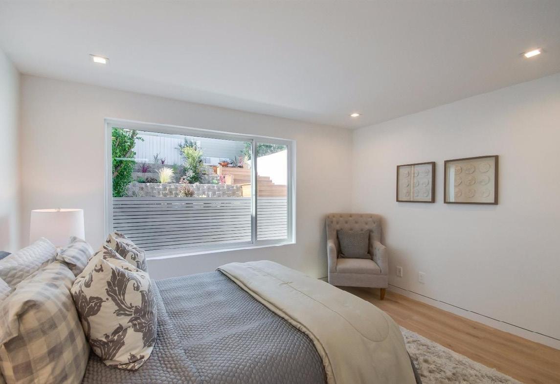
14 LEEGEORGE REMODELMCMPORTLAND Every habitable space in the house now features large windows connecting the interiors to the outdoors where Douglas fir trees surround the property.


16 LEEGEORGE
Contributions: Junior Designer/BIM Tech./Detailer/Construction Admin. Support/Visualizations
DN DN LEVEL 02 FLOOR PLAN PINE LAKE MIDDLE SCHOOL ISSAQUAH SCHOOL DISTRICT | 20 JANUARY 2017PROFESSIONAL PROJECT 3 Pine Lake Middle School Sammamish, WA | Completed 2018 | Mahlum Architects Phases: DD-CD-CA Renderings
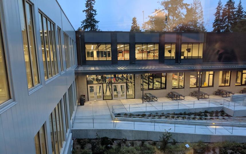
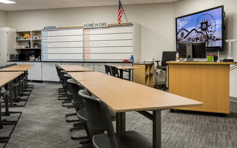
A replacement of an existing middle school for 1000 students. The design aspires to provide a well organized, day-lit environment for engaged students and access to the natural site. Four wings housing the administration, arts classrooms, athletics, and standard classrooms respectively enclose a central courtyard at the heart of the school. The project was carried out in a General Contractor/Construction Manager delivery process, which allowed close collaboration during construction to meet an exceptionally tight schedule. by George Lee

2017 MAHLUM ARCHITECTSCourtyard Lower Level 2017 MAHLUM ARCHITECTSCourtyard Upper Level


18SCHOOLMIDDLELAKEPINE LEEGEORGE 2017 MAHLUM ARCHITECTSCommons Gym Hallway


2017 MAHLUM ARCHITECTS


20SCHOOLMIDDLELAKEPINE LEEGEORGE 1 2 3 4 5 6 PINE LAKE MIDDLE SCHOOL 09 JUNE
CONFORMED2017SET
Under the project manager and project architect, I helped develop, coordinate, and maintain the BIM model to produce the main drawings, specifications, and details throughout the project. One of my primary tasks was to draw the interior and exterior details. Exterior detailing was a key challenge in accommodating 5 inches of continuous exterior insulation throughout the envelope. Details were scrutinized to ensure good airtightness and minimize thermal bridging in order to lower operational energy costs. I also created all visualizations for the project.
LEVEL 010"LEVEL 02 14' 42'ROOF0"4"LEVEL 03 28' 0" A.8 HALL3100 VESTIBULE1000A E4 F2 F2 F1 10'ACT-14" R1 R4 F1 10'S18" 10'GYP8" 801 A-512A-512C4D4 A-510D2 A-520C3A-520C1 A-513C2 A-510E3 A-516C3 B 61 8 LEVEL 010"LEVEL 02 14' 42'ROOF0"4"LEVEL 03 28' 0" 4 GYM1101 R1E2A-516C5 SIM DIV SCREENPROJECTION27PERELECT. LIGHT ELECTPERA-510B5SIM6112121444405 12 00 STEEL ANGLE PER05STRUCTURAL1200STEEL ANGLE PER05STRUCTURAL1200STEEL ANGLE PER STRUCTURAL 23 LEVEL 010"LEVEL 02 14' 42'ROOF0"4" A.1 LEVEL 03 28' 0" A GYM1101 R1 R4 E1 17'GYP8" A-516C1A-512D5 A-510A5 SIM 12 66 E3CLOSEDBLEACHERSTELESCOPING13INPOSITIONA-513C1A-524E6 SIM 23 B A C D 1 2 3 4 5 6 ABCD 1 2 3 4 5 6 ABCD ORIGINAL PROJECTISSUE: NO: DRAWN ISSUECHECKEDBY:BY:DATE: EE MARK DATE DESCRIPTION COPYRIGHT MAHLUM ARCHITECTS, INC. 2011 KEY PLAN FOR JURISDICTION USE ONLY: C:\~RevitLocalFiles\2016912-Arch-PLMS-V17_iwilson.rAM4:32:296/10/2017 PINE LAKE MIDDLE SCHOOL 3200 228TH AVENUE SE SAMMAMISH, WA 98075 2016912.00 IW,CONFORMEDNW,09 WALL SECTIONS - ZONE C NORTH AND A-315EAST1/2" = 1'-0"A1 WALL SECTION AT B/3.5 1/2" 1'-0"A3 WALL SECTION AT A.4/4 1/2" 1'-0"A4 WALL SECTION AT A/4.9 A-512 D4 STOREFRONT HEAD AT METAL PANEL STOREFRONT SILL AT CMU STOREFRONT SILL AT METAL PANEL B5 STOREFRONT JAMB AT FCPB4 STOREFRONT JAMB AT MP-1 D5 STOREFRONT HEAD AT FCP STOREFRONT SILL AT FCP D2 STOREFRONT HEAD AT CMU B2 STOREFRONT JAMB AT BRICK CMU A2 ALUMINUM SUNSHADE AT STOREFRONT HEAD A5 ROLLER SHADE DETAIL D1 STOREFRONT HEAD AT BRICK STOREFRONT SILL AT BRICK A1 PLAN DETAIL GRID B AT MAIN ENTRY A-519 C2 CANOPY CONCEALED GUTTER DETAIL D5 CANOPY TO METAL PANEL A5 MAIN ENTRY CANOPY EDGE C1 CANOPY GUTTER EDGE AT BUS ENTRY EXTERIOR SOFFIT RECESSED LIGHT POCKET A-530 E6 SEISMIC JOINT BRIDGE VIEW FROM WEST ENTRANCEE3 SEISMIC JOINT BRIDGE VIEW FROM COURTYARDE1 SEISMIC JOINT NORTH ENTRANCE A3 SEISMIC JOINT CLASSROOM WING VIEW FROM COURTYARD A6 SEISMIC JOINT CLASSROOM WING VIEW FROM SOUTH D.1 4 A.8 C PINE LAKE MIDDLE SCHOOL A-533 B6 SEISMIC JOINT FLASHING AT CANOPY PARAPET AXON E6 SEISMIC JOINT FLASHING AT PARAPET AXON C6 SEISMIC JOINT FLASHING CANOPY ROOF CURB- AXON B1 SEISMIC JOINT ENTRY CANOPY B3 SEISMIC JOINT ENTRY CEILING


24SCHOOLMIDDLELAKEPINE LEEGEORGE


26SCHOOLMIDDLELAKEPINE LEEGEORGE


28 LEEGEORGE PROFESSIONAL PROJECT 4 10th St. Condominiums San Francisco, CA | Completed 2016 | Alan Tse Design Phases: DD-CD-CA JuniorContributions:Designer/3D Modeller/Details/Construction Admin. Support/Visualizations A 5-story luxury condominium development in the Civic Center district of downtown San Francisco consisting of 28 1-bedroom & 2-bedroom units. Conceptually, the project is organized as set of shifted boxes representing each home. A variance was requested and approved from San Francisco’s typical bay window modulation requirement in order to maintain the width of these box volumes. Each unit is organized through one strip of public functions (kitchen, dining, living) & one strip of private programs (bedrooms, bathrooms). The separation also creates lightwells that allow every bedroom in the deep floor plates to have ample access to light and air. Photography by Bruce Damonte.


2 4 1
design
Working closely with the principal, assisted in the development and coordination of and through development, documentation, and
all main drawings, details,
construction administration.
construction
I
3D model information

Physical model by George Lee.

32DEVELOPMENTMAISONLA LEEGEORGE Photography courtesy of JS Sullivan Development


34DEVELOPMENTMAISONLA LEEGEORGE Photography courtesy of JS Sullivan Development


36DEVELOPMENTMAISONLA LEEGEORGE


38DEVELOPMENTMAISONLA LEEGEORGE Photography courtesy of JS Sullivan Development


JuniorContributions:Designer/3D
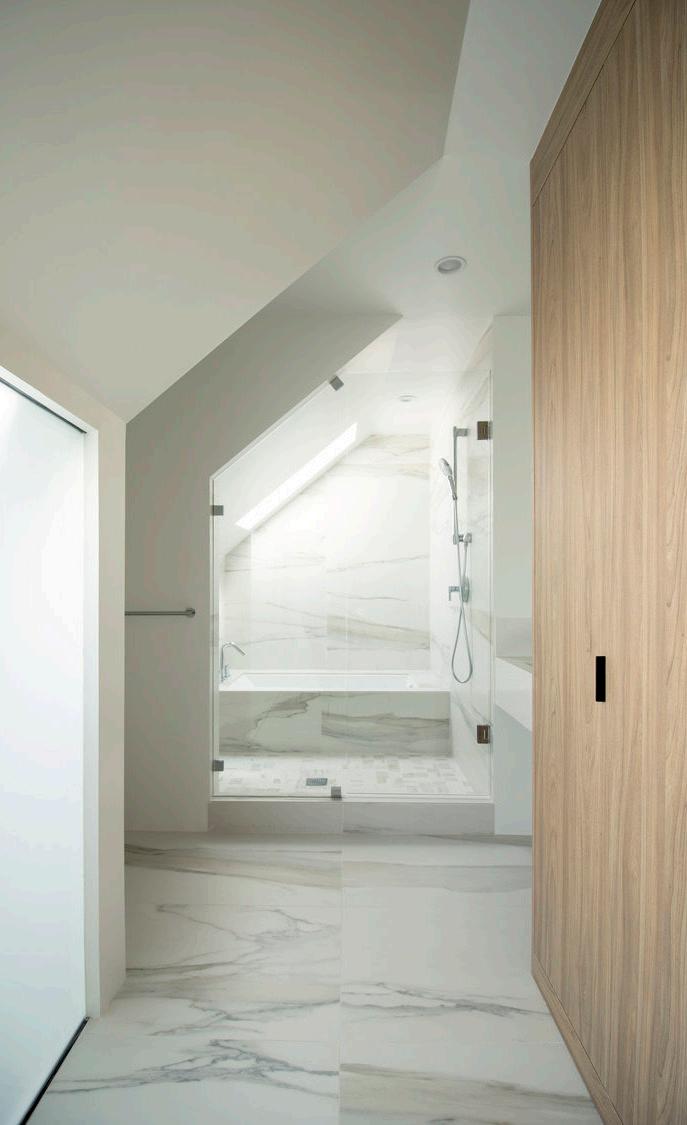
Modeller/Details/Construction Admin. Support Remodel of a 1908 San Francisco Victorian house. Due to poor conditions, this house was fully renovated into a 5 bedroom, 4.5 bathroom modern home. The design focused on an open, linear, layout linking all parts of the home to the backyard and maximizing available daylight with vertical openings. Unused attic space was converted to a main bedroom, a children’s bedroom, 2 bathrooms, and a laundry room. The en-suite main bathroom layout enabled a skylight shaft serve both the 3rd floor bathroom and the 2nd floor kitchen. Working closely with the principal, I assisted in the development and coordination of all main drawings, details, and 3D model information through design development, permitting, and construction documentation.
40 LEEGEORGE PROEFESSIONAL PROJECT 5 Potrero Hill Remodel San Francisco, CA | Completed 2016 | Alan Tse Design Phases: DD-CD-CA


42REMODELHILLPOTRERO LEEGEORGE


44REMODELHILLPOTRERO LEEGEORGE Photography courtesy of Alan Tse Design


46REMODELHILLPOTRERO LEEGEORGE


48REMODELHILLPOTRERO LEEGEORGE


50 LEEGEORGE PROEFESSIONAL PROJECT 6 Glen Park Remodel JuniorContributions:Designer/3D informationmaindevelopmentUndergarden,thengroundmechanicalandslab.withThehilltoplightwelltooriginalrestoredmuchWhilebathroomfullyDuethatRemodelVisualizationsDetails/ConstructionModeller/Admin.Support/ofa1962SanFranciscohousewasabandonedforover10years.tomoldanddecay,thehousewasrenovatedintoa4bedroom,3modernhome.rotdestroyedmostoftheinterior,oftheoriginalstructurewasandthelayoutmaintained.Thestructureyieldedopportunitiesinsertatransversestairwayandthatmaximizeddaylightandviews.housewasbuiltonseveregradeanunfinishedbasementwithoutaThebasementwasthenexcavatedfinishedtoaddafamilyroom,room,andbedroomonthefloor.Theexcavatedearthwasplacedtocreatetheterracedrearexposingadditionalviews.theprincipal,Iassistedintheandcoordinationofalldrawings,details,and3Dmodelthroughallphases. San Francisco, CA | Completed 2016 | Alan Tse Design Phases: SD-DD-CD-CA


Photography courtesy of Alan Tse Design

54REMODELPARKGLEN LEEGEORGE Photography courtesy of Alan Tse Design


1 2 3


4 AcademicSelectedProjectsWorks 1 | Seattle Water Research & Education Center 2 | Design for 203X: Living Architecture for the Sustainable Transition 3 | Scan|Design Foundation Studio: Folk High School for the Green Transition 4 | Selected Artwork 102945872

Seattle Water Research & Education Center
58 LEEGEORGE
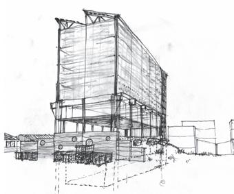
Water is a universal and powerful force in all our lives, deserving to be celebrated. The Seattle Water-ing Hall (Water Research and Education Center) celebrates the importance of water research through an inviting public interior space along the Seattle waterfront organized around the theatrical experience of water.
The building collects and invites water to permeate the entire structure, using a combination of water and architecture to subvert relationships of interior and exterior, and to give a sense of place on the working waterfront.
ACADEMIC PROJECT 1 University of Washington | Winter 2019 | Boris Srdrar Honorable Mention | ACSA 2019 Steel Competition


CENTEREDUCATION&RESEARCHWATER

2) Planes of water and a space of respite and contemplation on the ground floor as both research offices and a public space.
3) Falling droplets of water falling leading to an undeground space exhibiting the mysterious world of Elliot Bay.
60 LEEGEORGE
CENTEREDUCATION&RESEARCHWATERSEATTLE
1) Collected volumes of water to be processed, studied, and used at the rooftop.
The 3 platforms of the building develop a theatrical programmatic interpretation of unique experiences of water throughout.


CENTEREDUCATION&RESEARCHWATER
RESEARCH OFFICE
A B C D E F G H 1 2 3 5 4 5 A B C D E F G H 1 2 EXHIBITION HALL 1 EXHIBITION HALL 2 SEAWALL / ELLIOT BAY ACCESS WC WC LOBBY KITCHEN LOADINGDOCKMECH.
CAFE TAKE-OUT COUNTER PRESENTATIONFORUM (6) (5) (7) (7)
The building is an organized vertically as an open steel framework under a canopy of water and an envelope of light plastic film, or ETFE. The ground floor activates the street edge through an exhibition hall, cafe, take-out restaurant, and presentation space. The research office is a separated volume and mezzanine platform of wood. A strong cylindrical volume invites the public to journey down, underneath the city, to discover the underworld of the waterfront, which is mostly built on piers and piles. A rooftop bar becomes a lookout point from which both the natural context of the Olympics, Puget Sound, and downtown Seattle are all visible at the same time.

62 LEEGEORGE CENTEREDUCATION&RESEARCHWATERSEATTLE


cooling mode: cooled water running over atrium surface and in radiant tubing heat transferred from elliot bay to interior mylar ribbon & fiber optic filament water feature circulates cool water, providing dehumidification mylar ribbon & fiber optic filament water feature circulates heated water, providing humification heating mode: heat delivered through radiant floors and thermal mass water tank insulation water
toexcesspumpsheattransferredelliotbay
cooling mode: cooled water running over atrium surface and in radiant tubing mylar ribbon & fiber optic filament water feature circulates cool water, providing dehumidification water
oculusreciprocaltoexcesspumpsheattransferredelliotbayframeroof&skylight


132 1 - typical roof assembly steel membranesubframingpanelrigidinsulationcoverboardsteeldecking 2 - typical envelope assembly double-layer ethylene steel subframing steel tension cables 3 - typical floor assembly topping slab radiant subframingmembranereinforcedtubingconcreterigidinsulation glass-fiber-reinforced 1 - typical roof assembly steel steelmembranecoverrigidsubframingpanelinsulationboarddecking 2 - typical envelope double-layerassemblyethylene tetrafluoroethylene (ETFE) foil membrane aluminum subframing steel tension cables 3 - typical floor assembly (exterior) topping slab radiant reinforcedtubingconcrete slab glass-fiber-reinforcedsubframingrigidmembraneinsulation concrete cladding CENTEREDUCATION&RESEARCHWATER


570 - assignment 1 - tectonic section george lee helical screw piles concrete heavy timber structure dowel-laminated timber tension cable ETFE cladding arch 570 - assignment 1 - tectonic section george lee CENTEREDUCATION&RESEARCHWATERSEATTLE


This thesis presents a vision of how residential architecture must change to address the challenges of climate change and housing affordability while accommodating growth. Just as 194X influenced the post-war housing boom of the post-1945 era, a new visionary period called 203X must imagine what is needed to transform our environments for the sustainable transition.Theinvestigation spans the past, present, and future of the American single-family housing typology to understand and engage the dominant vernacular in the United States and Seattle. The project imagines what residential architecture would be if long-term sustainability and equity were the key drivers of design. The result is a framework called “Design for 203X” which proposes an incremental and flexible approach towards architecture, integrated with advances in other fields to increase human and environmental well-being for a more sustainable and equitable future. Thesis Project | University of Washington 2020 Jeffrey Ochsner and Gundula Proksch
| Winter/Spring
Committee:
Graduate
72 LEEGEORGE ACADEMIC PROJECT 2
Design 203X: Living Architecture for the Sustainable Transition
for


1. Social DevelopmentCommunity-LedFactors:
evaluatecommentimagine builddesignfinance communitylandtrust
74203XFORDESIGNTHESIS: LEEGEORGE
A Community Land Trust separates the value of land and the value of buildings through nonprofit leasing agreements in order to develop the homes and structures for community benefit. The CLT organization owns the land while residents own their houses. A scaling up of this type of idea is an important way to develop social values in the built environment. In designing for 203X, architects and designers must reclaim the role of innovating for the sake of better living. Architects could be continuous facilitators between the residents’ needs, dreams and built realities.

Community land trusts and other limited equity organizations are generally reliant on external funding for start-up, one of the reasons for their slow uptake. Therefore, CLTs will need to find paths to economic sustainability; they might develop additional housing on purchased land as well as other non-housing value such as food, water, and energy. In addition, policy could support such efforts through low-term financing, such as a housing bond. From a social perspective, the highest and best use of land is not to increase property value, rent, or mortgage cash flow, but to increase value for living. Models for Community Driven Development
2. Economic

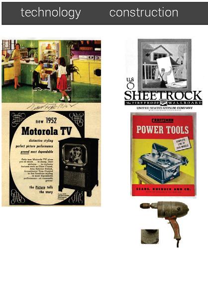
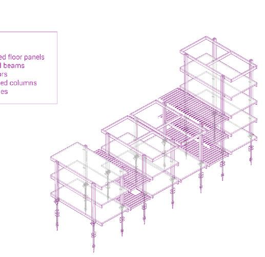
Structures designed for 203X cannot simply be incremental improvements over current models. To end the wasteful cycle of building, demolishing, and rebuilding structures, a dynamic and evolutionary architecture that can respond to change is needed. A dynamic and evolutionary architecture will need to use a “kit of parts” system to standardize the construction process to make it more efficient through the reduction of labor. This can be achieved through the reuse of existing materials and the use of low-carbon, recyclable substitutes for high carbon products like concrete.
3. Flexible & Evolutionary Construction Systems
76203XFORDESIGNTHESIS: LEEGEORGE


REGULATORY CHANGES
4. A Path from Low to High
end single-unit lots allow assemblythe of land parcels benecommunityfor fit extend height limits allow multi-unitmodelownershipforlots planningoutcome-basedmethods
Designing for 203X acknowledges that growth is necessary and that single-family neighborhoods eventually need to absorb some growth in population and change in demographics. To allow greater flexibility in every community, the regulatory environment for planning and construction processes must be rewritten to support maximum social impact from community developed land. Possible changes include: ending single unit lot maximums, developing an ownership structure for multi-unit land, allowing the assembly of land parcels for community benefit, increasing height limits, and developing outcome-based planning methods. Capacity
78203XFORDESIGNTHESIS: LEEGEORGE
Concept Diagram from the Zonnetorpe research project - http://www.zonneterp.nl/
Concurrent with new approaches to residential buildings, the systems that support buildings and everyday life must be re designed to be more integrated and decentralized to be resilient, extensible, and upgradeable. Services for water, heat, energy, and waste must be both circular and distributed. Innovation is needed to find ways to realize alternative systems that work socially and economically at scale. Integrated, Distributed & Upgradeable Systems
5.

80203XFORDESIGNTHESIS: LEEGEORGE DESIGN FOR 203X 12345New Ownership Models & Community-Led Development An Economic Model for Social &Integrated,toAArchitecturalDynamicImpact&EvolutionarySystemsPathfromLowCapacityHighCapacityDistributed,UpgradeableSystems FIGURE 6.2 - Layers of the Design for 203X framework. A Framework for Living Architecture
1 - The Patchwork House 4 - The Bookshelf House 2 - The Green Rowhouses 5 - The Cottage Assembly 3 - The Vertical Farmhouses These five points are essential components of an integrated plan for sustainability in the built environment. They are all important because they interact to form a cohesive synergy of innovations similar to the coalescence witnessed in the post-war period. To explore and present these ideas, the following are 3 sketch designs of what could be developed with the principles of Design for 203X. Designing for 203X: Sketch Proposals


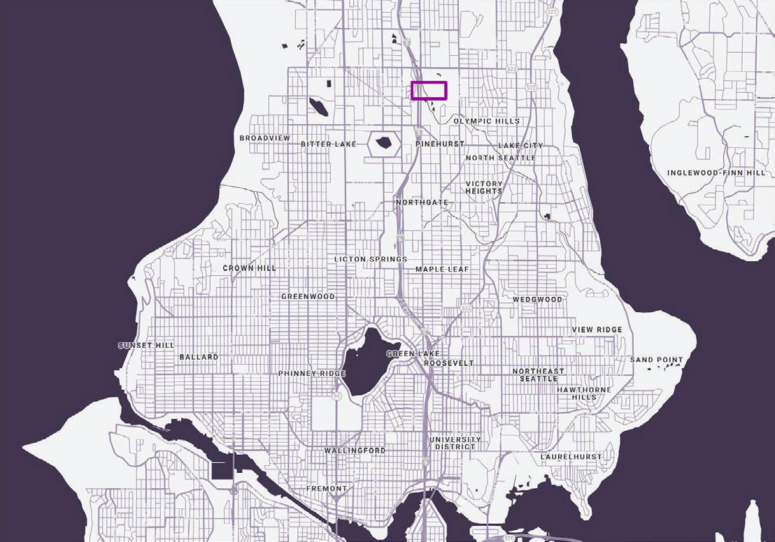
The hypothetical design area is located in the target neighborhood of Olympic Hills in North Seattle, a suburban area at the northern edge of Seattle characterized by post-war single family dwellings. The target neighborhood is an exemplary post war suburb, once affordable, but now growing increasingly unaffordable. Before development, the land in the area had been used for agriculture, including orchards and horse stables.
Study Hills Neighborhood, Seattle
82203XFORDESIGNTHESIS: LEEGEORGE
Area - Olympic


original
1)
for income 3)
ADU
2) expand
As designing for 203X takes hold and more and more land becomes developed for the community, new forms and typologies of larger communitydeveloped buildings could emerge. add & resilient features replace original home & add-on to ADU & upgrade structure integrate site with larger community developments
The neighborhood could be transformed through an incremental process starting with existing conditions. This transformation could follow a step-by-step process.
4)
Starting out with detached accessory dwelling units and then moving on to multiple full size houses, the later phases then link all the dwellings into one patchwork building that may continue to grow.
At the start, only a single-family house and a backyard cottage are located on the site. Seeing the original owners’ expansions, a neighbor soon joins in and adds new dwelling units to his property as well. As the co owners add more units, they eventually decide to form a cooperative and link the dwellings together.
phase 1 phase 2 phase 3 phase 4
The Patchwork House
84203XFORDESIGNTHESIS: LEEGEORGE Sketch Design 1:
This sketch design shows the growth of a multi unit co living building starting from one single-family lot and then developing incrementally in phases.

phase 5 1 BR 2 BR 3 BR 4 BR
LEEGEORGE


88203XFORDESIGNTHESIS: LEEGEORGE waterfoodenergyhomes childcare

89
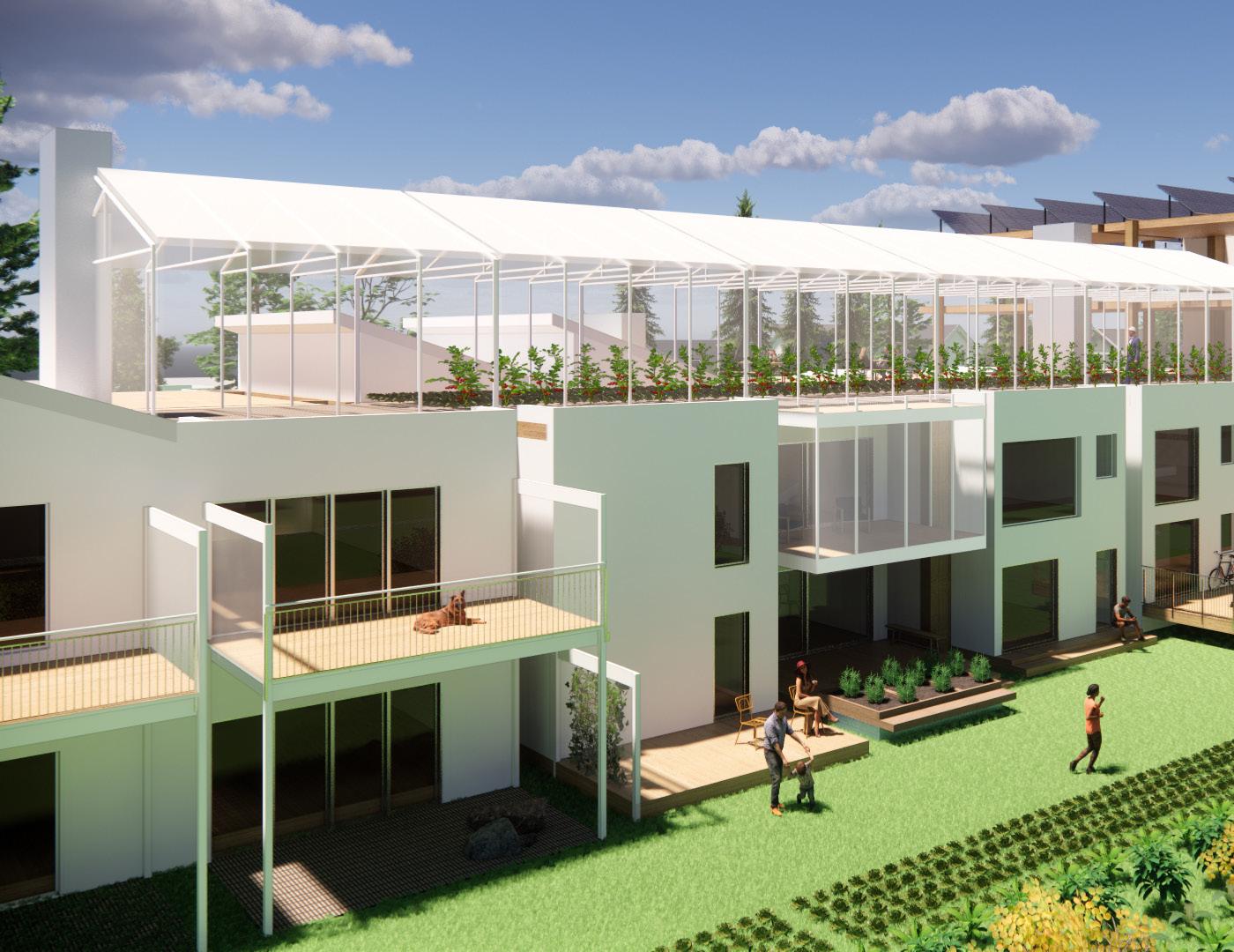
The Green Rowhouses
If more flexible architecture became a reality, residential development could foster new connections between communal space and private space. In this sketch design, the Green Rowhouses imagines the incremental development of individualized family dwellings in the row house typology. Above, at the roof deck, a shared greenhouse enclosure could provide a new type of semi-private or semi-public space that could include food production or a shared winter garden living space, while providing passive solar gains.
Sketch Design 2:


92203XFORDESIGNTHESIS: LEEGEORGE Sketch Design 3:
The Vertical Farmhouses
As design for 203X can adapt and accommodate community needs, the community could experiment with other key ideas in sustainability such as localized food production. This sketch design imagines urban agriculture in a greenhouse enclosed vertical farm built next to a grouping of cottages using the hybrid steel-and-timber construction system. The vertical farm is a testbed for highly productive technologies such as hydroponics and aquaponics in combination with rainwater harvesting and earth-sheltered food storage. Underneath the farm, local food businesses selling and cooking with the onsite produce might thrive as a local gathering place.


STUDIOSCAN|DESIGN

ENGAGE WITH
INTEGRATED LANDSCAPE
Folk High School for the Green Transition - Campus Plan
94 LEEGEORGE ACADEMIC PROJECT 3 (GROUP)_ A.SNOW | BARR | LEE | URBO
INCREASED DENSITY
INTEGRATED BIOSCAPE
INTIMATE SOCIAL SPACES
PERMACULTURE ORCHARD/LIVESTOCK WHEAT HERBS/SPICES University of Washington | Fall 2019 | Peter Cohan, Sinus Lynge & Tue Foged Scan|Design Foundation Studio | EFFEKT Architects | Copenhagen, Denmark Team Members: Alex Barr, Katherine Acheson-Snow, George Lee & Gerte Urbon TRANSITIONGREENTHEFORSCHOOLHIGHFOLK
CROSS POLLINATION
A.SNOW | BARR | LEE | URBO
SUSTAINABILITYCOMMUNITY
Integrate both landscape and architecture a fertile, regenerative bioscape
A.SNOW | BARR LEE URBO
|
Promote a rich social and mental life through public and intimate spaces.
Integrate both landscape and a fertile, regenerative bioscape
INTIMATE SOCIAL SPACES
INCREASED DENSITY
Distribute building systems for ENGAGE WITH
CROSS POLLINATION
|
Develop a cross-pollination of programming Connect with the larger community
Promote a rich social and mental life through intimate spaces
This concept master plan for the new Folk High School for the Green Transition is a vision of a broad learning environment that integrates a lively setting for community and social responsibility with a reimagining of how the built environment inhabits landscape and ecosystem. The plan imagines the campus as a framework of flexible spaces, fully integrated with a regenerative agricultural bioscape. This framework creates a variegated and flexible mix of uses where students learn, eat, rest, and work together.
Integrated Bioscape Integrate both landscape and architecture in a regnerative and fertile bioscape that is productive for both the school and the environment.
SUSTAINABILITYCOMMUNITY
Intimate Social Spaces
Develop a cross-pollination of programming Connect with the larger community INTEGRATED BIOSCAPE
Increase the density of uses and
Sustainability Develop the land responsibly by designing with the natural flows of water, topography, and the local ecosystem. Distribute building and ecosystem services throughout.
Diverse and Mixed Programming Create a rich blend of programmed spaces encouraging a synergy between individuals, groups, and subjects within the community and a cross-pollination of ideas.
Increase the density of uses and value
Promote a rich social and mental life through intimate spaces Distribute building systems for sustainability
The campus plan recognizes the challenge of the Green Transition as a society-wide imper ative, encouraging gathering as individuals, groups, peers, and citizens. The community at large in Hvalso and beyond is invited to par ticipate through a variety of spaces designed to welcome all to participate and interact in these efforts. The rich social life of the cam pus is fostered at all scales and conducted by valuing democracy, universalism, and respect in open dialogue.


groups, peers, and citizens. The community at large in Hvalso and beyond is invited to par ticipate through a variety of spaces designed to welcome all to participate and interact in these efforts. The rich social life of the cam pus is fostered at all scales and conducted by valuing democracy, universalism, and respect in open dialogue.
LEEGEORGE
The mix of uses focuses the campus on the school’s primary mission: a critical examination of the sustainability of the modern human lifestyle. In combining this framework of spaces with a productive bioscape, the campus is intended to demonstrate a new concept of well-being which is intended for the needs of both humans and the environment in a carbon-neutral society.

This project explores the integration of agriculture with the dining hall as a way of celebrating a greater connection between people and food in the Folk High School for the Green Transition. The dining hall incorporates experimental indoor, vertical, hydraulic farms into a dynamic and multipurpose gathering space. The indoor farm volumes function partially as greenhouses as well as providing the primary source of natural light in the dining space. The dining hall is imagined as a scaffolding for the greenhouse volumes through the use of a simple modular timber grid construction system. The ground floor is kept as open as possible using the timber frame structure and glass sliding door panels in order to extend the dining hall into the adjacent exterior plaza.
96 LEEGEORGE
Folk High School for the Green Transition - Dining Hall ACADEMIC PROJECT 3 (INDIVIDUAL) University of Washington | Fall 2019 | Peter Cohan, Sinus Lynge & Tue Foged Scan|Design Foundation Studio | EFFEKT Architects | Copenhagen, DenmarkTRANSITIONGREENTHEFORSCHOOLHIGHFOLK


102 LEEGEORGE ACADEMIC PROJECT 4 Selected Artwork Mixed media artwork by George Lee (Ballpoint pen, colored pencil, graphite & watercolors on paper.)


LEEGEORGE thank you