38 minute read
Sponsored article by Seafl oor Systems


Utilizing New Methods to Research Impacts on a Precious Waterway
Unmanned Vessels to Assist in Saltwater Intrusion Research
Seafloor Systems, Inc. was recently contracted by the U.S. Geological Survey (USGS) to develop two custom HydroCat-180 unmanned surface vessels (USVs) that will be used to monitor the impacts of saltwater intrusion from the Pacific Ocean into the Sacramento-San Joaquin Delta in California. The subsequent research using the new autonomous vessels will provide new insights into maintaining balance within the complex ecosystem.
Turning Tides
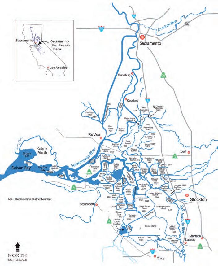
The Sacramento-San Joaquin Delta, commonly referred to as the California Delta, is the hub of the state’s water supply system and a teeming wetland bionetwork (Figure 1). About 500 plant and animal species call the area home, making it one of the largest estuaries in western North America. Two-thirds of California’s salmon pass through the delta on their way upstream to spawn, as well as half of the state’s migrating waterfowl.
As settlers began to inhabit the area in the mid-nineteenth century, they saw enormous agricultural potential in the natural peat soils, which are rich in nitrates from partly decomposed organic matter. Reclaiming the land for farming meant building dirt levees to prevent periodic flooding of brackish semi-salty waters that could ruin crops. In the process, it disrupted natural habitats.
Many species, including the delta smelt, have experienced habitat loss and detrimental change since farmers began to convert their territory into agricultural lands. In addition to agricultural activity, the man-made California Aqueduct system that transports fresh water to southern California redirects the flow of water from north to south as opposed to the natural west to east direction. Coupled with increasingly common droughts, the flow of fresh water from the Sierra Nevada Mountains to the delta has been reduced, causing significant salinity intrusion.
Figure 1: The California Delta is formed at the western edge of the Central Valley by the confluence of the Sacramento and San Joaquin rivers and lies just east of where the rivers enter Suisun Bay. (Image Courtesy: USGS)
The growing delta water quality issue provides the impetus for agencies like the USGS to observe and mitigate the effects of saltwater intrusion. On the one hand, California relies on the water arteries for farm irrigation and drinking water. On the other, the fragile habitats of native species are being altered at an alarming rate.
surveying a dynamic environmenT
The delta is an extremely diverse environment, meaning that traditional hydrographic survey methods struggle to account for the constant change that takes place from one minute to the next. The delta is heavily influenced by the Pacific Ocean, taking its cues from the motion of high and low tides. Consequently, the flow rate and water levels can change rapidly in a given day. Pile on the potential for rainfall upstream in the neighbouring Sierra Nevada Mountains and Central Valley, and survey readings can become skewed. From a safety standpoint, sediment and debris can wash downriver, creating potentially hazardous conditions for the use of manned vessels in the delta during the winter and spring months.
Previous survey efforts by the USGS relied on a manned vessel to hold a strict transect across the water, which can often take more than 30 minutes to complete. During this time, the water level can change by more than 10 feet (3 metres), resulting in inconsistent data acquisition. With their new HydroCat-180 USVs (Figure 2), the USGS hopes to cut the data collection time in half, improve the track line by 95%, and significantly increase the accuracy of the resulting water flow and depth model. Personnel will reduce their exposure to risks caused by rainfall and flooding events.
Flow rate and depth data will be collected using an RD Instruments Acoustic Doppler Current Profiler (ADCP), mounted under the payload deck of the USVs. The two USVs will simultaneously conduct surveys along pre-programmed routes, transferring the task of maintaining a precise track line to Seafloor’s AutoNav system (Figure 3). Known in the hydrographic survey industry as ‘mowing the lawn’, the action of the two vessels traversing the water while emitting high-frequency pulses of sound ensures an adequate amount of data collection. The USGS cannot disclose many of their practices with the new vessels, but the corresponding data will shed light on the intrusion of saltwater into freshwater zones of the delta.
Preserving The delTa for The fuTure
The landmark contract with the USGS was awarded to Seafloor Systems with a six-month deadline and, despite some supply chain issues caused by the COVID-19 pandemic, the vessels were completed and delivered ahead of schedule. Seafloor, which up until now has focused its efforts on smaller, calm water vessels, hopes that this application of the two 18ft (6m) HydroCat-180s will expand its reach into the nearshore maritime sector. Located a mere hour’s drive from the delta region, Seafloor has a vested interest in protecting the precious natural resources in the region. There is no easy answer to how the state will handle this growing issue, but frequent scientific observation is a key component in taking the next steps. The HydroCat-180 USVs will strengthen efforts to form a symbiotic relationship between a modern society and the natural environment.
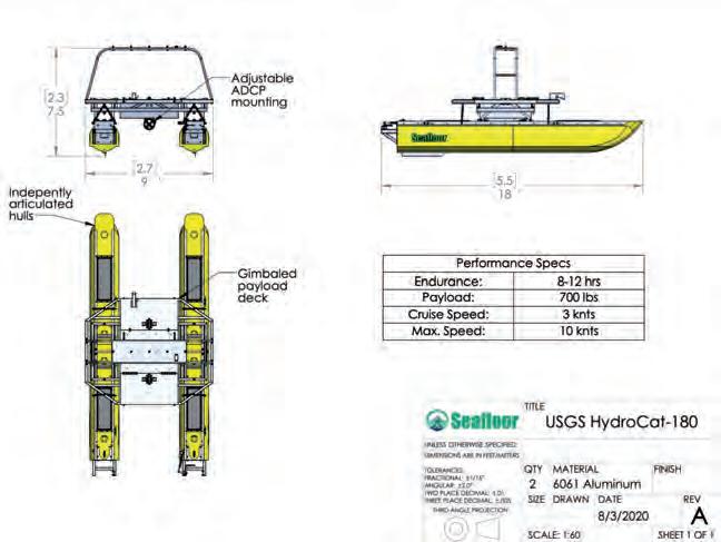
Figure 2: Design blueprints show key features of the HydroCat-180, Seafloor’s largest unmanned vessel built to date.
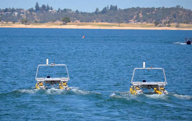
Figure 3: Two HydroCat-180 unmanned surface vessels will work in tandem to survey the California Delta.
What is ‘Hydrospatial’?
In the last decades, we have progressed from ‘graphic’ to ‘digital’ and now to ‘spatial’. During the opening plenary session of the Canadian Hydrographic Conference (CHC) 2020, the author made a presentation on ‘What is Hydrospatial?’, before inviting a panel of four senior figures and the audience to discuss the topic.
The Issue
The objective is not to oppose the words Hydrography and Hydrospatial; but to present that Hydrospatial is an expansion of Hydrography. What we do and its impact is obviously more important than a word can convey. However, words are how we express ourselves and, in particular, how we transmit our ideas and concepts to others. The marine geospatial revolution is so dramatic that it is recommended to adopt a new word to describe it; a word that conveys the image of the modern, hi-tech, multi-role, digital data environment in which we now operate. This word is ‘hydrospatial’.
Why, When, Who, Where, hoW & WhaT!
The type of data and the way in which hydrographers collect it is expanding, and the scope now goes well beyond nautical charting for safe and efficient navigation. This variety of data is now used and fused with data from land, coastlines, inland waters and offshore. This is the ‘why’ and the ‘when’ of hydrospatial! Both defence and commercial shipping users of traditional hydrographic products, data and information now seek additional information and capabilities from hydrographic data. An ever-increasing community of additional users that seeks a green future through a sustainable blue economy is joining them. These are the users ‘who’ need hydrospatial data.
The managers of coastal zones must consider sea-level rise, coastal erosion, crustal subsidence and much more. Nearshore, offshore and remote areas everywhere
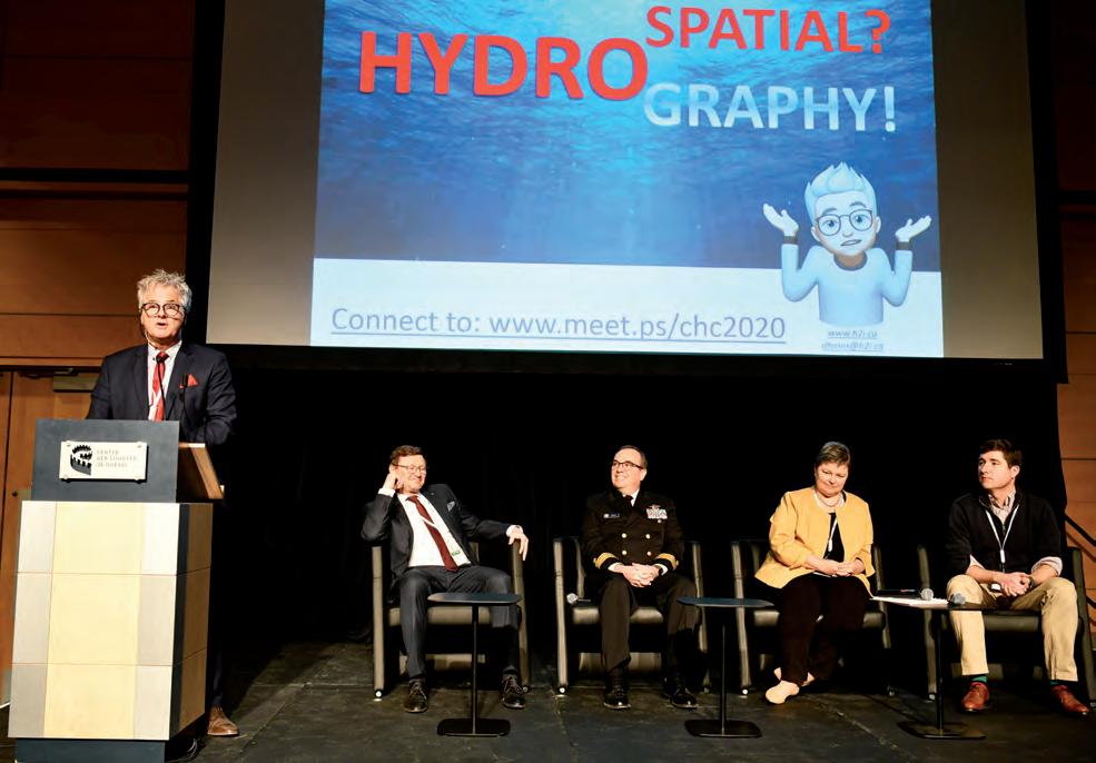
Denis Hains (speaker), seated left to right: Dr Mathias Jonas, Secretary General of IHO; Rear Admiral Sheppard Smith, Director of the Office of Coastal Surveys with the United States National Oceanic and Oceanographic Administration (NOAA); Dr Geneviève Béchard, Hydrographer General of Canada and Director General of the Canadian Hydrographic Service (CHS); Dr Ian Church, Chair of COMREN and Assistant Professor at the Ocean Mapping Group (OMG) of the University of New Brunswick (UNB), Canada.
(including polar regions) are becoming more accessible and attractive both for natural resources and for adventurers. All of this drives the need for ‘where’ hydrospatial is needed.
Faster adoption of all remote sensing technologies and various autonomous crafts for marine data acquisition (satellite, airborne, surface, underwater, etc.) is needed. These are ‘how’ high-tech capabilities evolve and they deserve to be recognized with a name like ‘hydrospatial’, which inspires inclusion beyond the traditional.
The suggesTeD DrafT DefInITIon
It is suggested that the definition of ‘what’ hydrospatial is be based on a modified version of the existing February 2020 International Hydrographic Organization (IHO) definition of hydrography, as follows:
25/02/2020: Hydrospatial is the branch of applied sciences which deals with the analysis, understanding and access to static and dynamic marine geospatial digital and analogue data and information, digital signals, measurement and description of the physical, biological and chemical features of oceans, seas, coastal areas, lakes and rivers from all possible available data sources in near-real time and real time, including their history and the prediction of their change over time. This for the purpose of: timely access to a standard, high-quality and the most up-to-date marine spatial data infrastructure; safety and efficiency of navigation; and in support of aquatic and marine activities, including sustainable blue environment and economic development, security and defence, and scientific research.
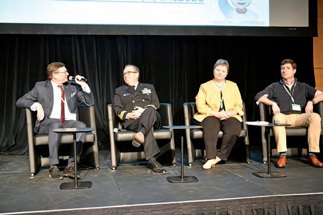
QuoTes from The PanellIsTs
Based on the opening presentation, the four panellists aired their views, including the following quotes:
The IHO Secretary General commented: ... “to adopt a new word and official definition in the IHO Hydrographic Dictionary S-32 would require a formal proposal put forward to the affected experts of IHO’s Hydrographic Dictionary Working Group. Hydrography is clearly going through major important changes that will require an expanded role serving an increasing group interested in the blue economy proponent... If this requires a new word to express the expanded scope and to address the third and fourth dimension of our undertakings, ‘hydrospatial’ will find its way into our spoken and written language.” The Hydrographer General of Canada remarked: …“showing how a new word can fill a gap by using it in sentences is more important than having it officially adopted. Just use it!”
The Director, US Office of Coastal Surveys, provided the comment: …“The field of hydrography is changing rapidly – we have access to both a wider variety and a bigger volume of relevant data than ever, and the demand for our data and expertise is growing beyond charting. This conversation about the language of identity is just the beginning. We need to also take a hard look at our education and qualifications in light of these changes.”
The Chair of the Canadian Ocean Mapping Research & Education Network (COMREN), representing Academia, said: … “accredited academic programmes have already added material, courses and learning objectives that go beyond international requirements to adapt and keep up with the rapid technological changes in hydrography that could be qualified as hydrospatial... ”
Dr Mathias Jonas providing his perspective.
engagIng The ParTIcIPanTs
During this session, a live voting application to engage the audience was used. Detailed questions and results can be found in the Note published in the IHR. The vast majority considered that hydrography is going through a very important period of change, that education and training is adapting well, that hydrography is impacted by Artificial Intelligence (AI), that more time will be invested in data quality from multi-sources than from field work, and that more data will be acquired through crowdsourced bathymetry, satellite-derived bathymetry and autonomous platforms. The majority agreed to adopt the word ‘hydrospatial’.
conclusIon
Traditional hydrography as we know it, both in the past, now and for the future, is essential. Hydrospatial does not replace nor diminish hydrography, it expands it. As we enter the United Nations Decade of Ocean Science (2021-2030) and start the Nippon Foundation Seabed 2030 Project, moving toward the greater use of the word ‘hydrospatial’ highlights the traditional benefits and role of hydrography, while also emphasizing the new roles for our hydrographic geospatial data and the expertise in an exciting, modern and inspirational way.
This article is a summary of a detailed published note in the International Hydrographic Review (IHR), May 2020 Edition on page 84-93 at: https://iho.int/uploads/user/pubs/ ihreview_P1/IHR_May2020.pdf.
Denis Hains hold a Bachelor Degree in Geodetic Sciences from Laval University and is a Québec Land Surveyor. He worked for 35 years in the Public Service of Canada in Fisheries and Oceans Canada – including the Canadian Hydrographic Service (CHS), the Canadian Coast Guard and Natural Resources Canada’s Canadian Geodetic Survey. He retired as Director General of CHS and Hydrographer General of Canada in 2018. He is the founder and CEO of H2i. He is also a Member of the Editorial Board of the International Hydrographic Review and the Strategic Advisory Group of The Nippon Foundation-GEBCO Seabed 2030. He is an Affiliate Research Scientist at the University of New Hampshire and a member of the Québec Land Surveyors Modernization Committee. dhains@h2i.ca
Reducing Requirements for Manual Intervention The Road to Autonomy: Unmanned Subsea Asset Inspection
In 2019, Swire Seabed successfully used a novel AUV/USV solution to complete a commercial pipeline inspection campaign, surveying 175km of pipe. This involved the use of a HUGIN AUV paired with the Sea-Kit Maxlimer USV. The 2019 survey campaign formed the final part of a developmental project involving Swire Seabed, EIVA, Kongsberg and Sea-Kit in which inspection work scopes were completed for Equinor. In this, emphasis was placed on the automation of survey processes, allowing remote command and control of operations. This work typifies the direction in which the industry is heading, with many survey companies now seeking to reduce requirements for manual intervention.
We are currently witnessing a rapid shift in the field of subsea survey and inspection, towards remote operations completed by unmanned vehicles. Automation is at the heart of this shift, and to reduce reliance on manual intervention and control, increasing levels of automation are required. Between 2018 and 2020, a commercial developmental project was undertaken by Swire Seabed, with Equinor as a client. The project aimed to implement automated processes in remote survey operations, to enable unmanned subsea pipeline inspections to be completed. The project successfully demonstrated how inspection campaigns can be undertaken with no personnel at sea, using an Autonomous Underwater Vehicle (AUV) operated from an Unmanned Surface Vehicle (USV), with missions controlled from a remote operations centre on land. Survey software running onboard the AUV facilitated in-mission data processing and the generation of vital alarms and quality control (QC) messages. These were relayed to shore, allowing mission alterations and retasking decisions to be made. The project resulted in the successful completion of the first commercial combined AUV/USV pipeline inspection campaign with over-thehorizon operations, and with pipline extents surveyed up to 100km from shore. This unmanned system was effectively used to create a standard set of pipeline inspection deliverables, as defined by Equinor.
Survey WorkfloW
In 2018, Swire Seabed (who have now ceased operation), formed an agreement with Equinor to undertake a series of pipeline inspection work scopes using unmanned survey methods. The project required the combination and integration of existing technologies and methods in a novel manner. This also required new processes and procedures to be formulated, in addition to the automation of some of the standard, routine tasks usually completed as part of a survey workflow. Therefore, to meet obligations to Equinor, operational capacity had to be developed to allow unmanned subsea pipeline inspections to be completed using an AUV, launched and recovered from a USV. The Kongsberg Maritime (KM) HUGIN AUV was selected for the project and two additional onboard computers, supplied by EIVA, were installed on the HUGIN, one of which ran automated survey workflows (via Workflow Manager (WFM) software), and the other Deep Learning (DL) processes. A simple set of objectives was linked to the software implemented on these boards, including the implementation of functionality for real-time pipeline tracking and eventing, the creation of self-actuating data processing workflows, active QC, alarm generation, the automation of data analytics, and navigation aiding. Together, these functions form some of the fundamental actions required within the data ETL (Extract, Transform, Load) pipeline for autonomous subsea inspection operations. Furthermore, if successfully implemented onboard unmanned maritime systems (UMS), these processes could pave the way to removing existing client requirements for the use of large survey vessels,
1 2
Mission planning Commands sent to USV: runlines, CTS, tracking
10 9
AUV retasking decisions Transmission of data outputs to shore, QC
3 4
AUV launch, dynamic nav
8
Transmission of inmission updates (via the USV), onboard data processing, alarms, error ID, QC
7
Remote interrogation of USV based processes, status updates USV based selfactuated data processing
5
AUV in-water retasking
6 AUV recovery, charging, data download
Shore-based activities Shore/USV activities AUV-based activities USV-based activities
Figure 1: AUV/USV unmanned inspection process diagram (CTS – course to steer).
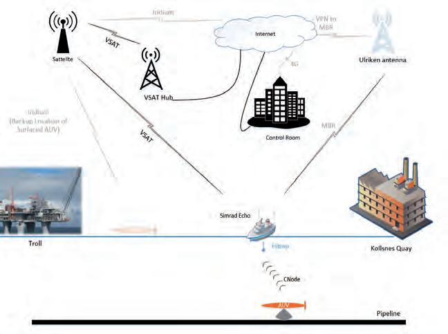
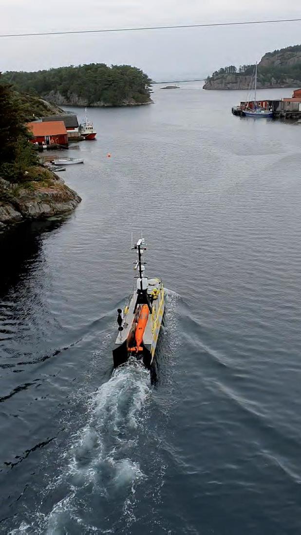
Figure 2: Pilot 1 operations – communication set-up.
Figure 3: Sea-Kit Maxlimer transiting to commence inspection operations with the HUGIN AUV onboard.
manned by extensive crews, for the completion of subsea pipeline inspection tasks. The main activities completed during the project comprised of ongoing R&D works undertaken by development teams at Swire Seabed and EIVA, sea trials completed at KM’s base in Horton using the HUGIN, and two pilot projects in which inspection campaigns were completed for Equinor. These pilot projects, which ran in 2018 and 2019, involved the inspection of seven of Equinor’s pipelines located close to Bergen, Norway, with a combined length of over 350km. The project was drawn to a premature close early in 2020 due to the unexpected closure of Swire Seabed. Prior to this, however, the next phase of the project had commenced. This involved the design and build of a large USV, with facilities for launch, recovery and charging of an AUV, capacity for data download, and an onboard data management centre. Construction and subsequent use of such a craft was recognized as necessary to allow completion of extended missions, involving multiple AUV dives. The concept of UMS subsea pipeline inspection was effectively proven during the pilot projects; however, for this to be realized as a realistic commercial alternative to existing survey solutions, the operational limitations, which imposed constraints on the number of AUV dives per USV voyage, would need to be removed. A flow diagram of the typical processes to be completed in a combined AUV/USV inspection campaign is detailed in Figure 1. During this project, it was not possible to implement all the processes listed in this diagram as only a single AUV dive was completed within each mission offshore. The operational capacity implemented during the pilot projects did allow processes one through to five to be completed. It was envisaged that utilization of the larger, planned USV would facilitate completion of the remaining processes.
Pilot ProjectS
The first pilot project was completed for Equinor in 2018. This tested the operational procedures that Swire had developed for running a full survey campaign remotely from a shore-based control centre. Overall, Pilot 1 was successful and the pipeline assets linking Equinor’s Troll field to their Kollsnes processing plant on the island of Sotra, close to Bergen, were inspected. The communication infrastructure at the heart of these remote operations was, and is, the enabling factor allowing such unmanned processes to occur. Figure 2 provides a rough indication of the communication lines utilized in the project, with satellite communications and Maritime Broadband Radio (MBR) forming the main communication links.
The Sea-Kit Maxlimer USV was planned for the project in Pilot 1, but due to a clash in timings it was not available. As a result, the project resorted to using a manned vessel (the Simrad Echo), which simulated the role of a USV. Operations were still completed in the same manner, with command and control situated onshore, but manual AUV launch and recovery was required. This was not the case in Pilot 2, where it was possible to pair the HUGIN with the Sea-Kit USV (Figure 3). During Pilot 2 missions, successful unmanned AUV launch and recovery was completed offshore. Data acquisition was controlled and monitored from the shore-based control centre, and four pipelines with a combined length of 175km were surveyed. Operations undertaken as part of Pilot 2 included a world-first for an over-the-horizon commercial pipeline inspection using UMS. No external assistance was provided to the operation of the USV and AUV; however, due to regulatory requirements in place in 2019, a guard vessel remained in the vicinity of the USV during missions.
SoftWAre AutomAtion
EIVA developed software functionality during the project, which was installed on the two boards integrated into the HUGIN AUV. In pilot project operations, EIVA’s DL board was used primarily for pipe tracking using image data, while their WFM board enabled data processing to begin onboard the AUV, for alarms to be generated and transmitted to shore, and for data QC and analysis to be undertaken. Figure 4 shows a post-mission visualization generated, illustrating the Top of Pipe (TOP) position created in real time, using functionality installed on the DL board; image data corresponding to the on-screen tracking point is shown in the left of the figure. Additional pipe tracking methods based on Multibeam Echosounder (MBES) and laser data were developed during the project and tested in simulator dives following Pilot 2; however, it was not possible to implement these methods on the HUGIN prior to the project’s cessation.
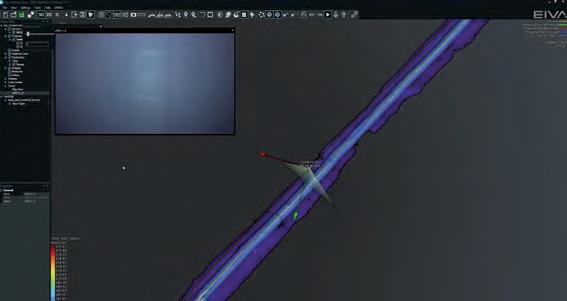
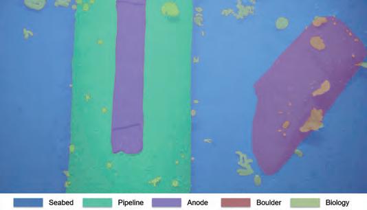
Figure 4: Image showing a pipeline track as detected in real time from image data during Pilot 2. The tracking point on-screen accompanied by red and green arrows indicates the camera focal point that the image in the top left of the screen relates to.
Figure 5: An example of DL-based automatic pipeline eventing using image data (Image Courtesy: EIVA).
The DL pipeline eventing methods developed by EIVA were implemented offline during the course of the project and tested using data obtained from both pilot projects. However, the longer-term goal was to migrate these processes to the DL board onboard the HUGIN, so that eventing could be carried out in near real time. The DL eventing methods that were developed did prove effective in identifying field joints and anodes (Figure 5), and in addition to providing event listings, functionality was developed to use detected features for navigation aiding. Post Pilot 2, EIVA refined a navigation aiding method based on anode identification, which involved comparison of the known and observed positions of detected anodes. The long-term aim of this, and other similar navigation aiding methods under development, is to generate outputs that can feed back into the HUGIN’s control system to form dynamic navigation aiding inputs.
It was possible to implement a range of software functions during the pilot projects, most of which involved processes developed for the WFM board. Self-actuating data processing workflows were tested during Pilot 2, and these allowed data processing, cleaning and QC tasks to commence onboard the AUV and then to continue onshore post-mission. In addition to this, the WFM board also ran processes that triggered alarms when specific conditions were present, such as poor visibility, inadequate data coverage, missing sensor inputs, and the pipeline not being detected. It was possible to transmit these alarms to the USV via a low-bandwidth acoustic link. The alarms were then transmitted back to shore, alerting operators of critical conditions so that a manual decision could be taken for the in-mission retasking of the AUV. During the pilot project, alarms were only used to inform operators; however, the longer-term plan is for the outputs of these alarms and QC processes to form inputs to automated AUV retasking routines.
A range of pipeline inspection-specific analytical processes were also developed during the project and run offline. However, EIVA’s aim is to slowly migrate these processes to the onboard computer running WFM. Despite these processes not being tested operationally onboard an AUV, simulator tests revealed that significant time and efficiency gains were possible by running the automated analytical processes developed, such as pipeline digitization, tagging, data classification and QC. For example, functionality was developed for the automated cleaning of MBES data points based on pipe diameter, once TOP was determined from pipe tracker data. The automation of data processing, cleaning, QC and analysis was recognized as essential to furthering the levels of automation possible in UMS inspection missions. Many of these tasks would normally be completed manually offline, yet they form vital inputs to AUV retasking decision-making processes. Automation of such functions, and the ability for these to be completed onboard an AUV prior to its recovery, could radically reduce the overall duration of inspection campaigns, especially if it were possible for the outputs of these tasks to form inputs to automated retasking routines.
the end of the Beginning
Despite this project having ended, in the words of a great man: “Now this is not the end, it is not even the beginning of the end, but it is, perhaps, the end of the beginning” (Winston Churchill, 1942). Work in this field is progressing rapidly, and the benefits of further progressing unmanned pipeline inspection solutions are obvious: efficiency gains, reduction in costs (vessel time and man hours), and minimization of environmental impacts. However, a significant distance is yet to be covered along this road to automation. While we are now able to complete unmanned operations with humans in the loop as remote decision makers, in the near future we aim for the automatic in-mission retasking of UMS, allowing larger work scopes to be completed. The ultimate goal is for the role of humans in this loop to diminish to a level where we are only required to oversee operations. Lessons learnt during this project have highlighted the importance of focusing on a number of key areas to achieve this goal, including hardware and software development, optimization of maritime communications, automation of data processing and analysis, navigation aiding, and automated AUV retasking.
Al Rumson is Innovation Lead for Sulmara Subsea, a young subsea service provider that aims to be disruptive and innovative. His work involves sourcing and implementing new technical solutions to subsea survey and position challenges, with a focus on automation and unmanned solutions. He has worked in the subsea industry since 2006, based primarily in Norway since 2011, and previously worked for DOF Subsea and Swire Seabed. In recent years, Al has been involved in the research and development of unmanned survey solutions, focusing specifically on the management and use of subsea datasets. He holds a PhD relating to coastal and ocean data analytics from Cranfield University. alexander.rumson@sulmara.com
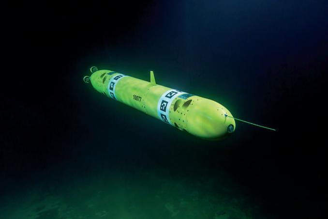
Research Platform with Unique Six Degrees of Freedom Control Capabilities
Introducing MARIN’s mAUV
Autonomous underwater vehicles are becoming more and more common in the maritime industry, and technology is rapidly developing for different applications, such as inspection, maintenance and surveillance. Meanwhile, more advanced autonomous capabilities are required, to be able to perform complex tasks and challenging missions. The Maritime Research Institute Netherlands (MARIN) has designed and built a modular Autonomous Underwater Vehicle (mAUV) for research projects in its model basins. The objective of this research effort is to expand the knowledge of vehicle control and to gain a better understanding of autonomous underwater operations.
MARIN has a lot of previous experience with dynamic positioning (DP) systems for ships and offshore structures and with autopilots for sailing ships. It has also built free sailing models of submarines, which include autopilots and control with rudders and sail planes. Experience in these areas played an important role in the development of the mAUV. The challenge was to develop an underwater vehicle with full six degrees of freedom (DoF) control, without any limitations. Furthermore, the aim was a vehicle capable of efficient travel at high forward speed while also able to hover in a fixed position and orientation. This is a unique combination of capabilities. The mAUV is now operational, with vehicle control and path-following available and tested. The next steps are autonomous capabilities, including advanced navigation, collision avoidance and additional actuators.
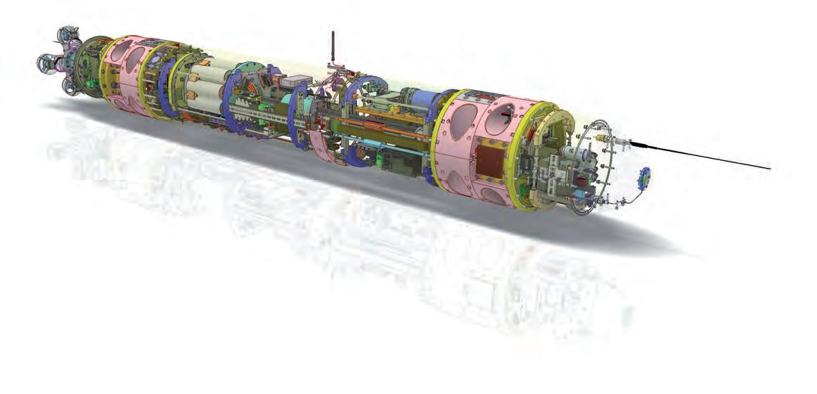
Vehicle concept
The vehicle concept development started with the definition of a number of (self-imposed) design requirements, including the ability to control in all six DoF, combining hovering with travelling at high forward speeds, and a modular construction, allowing for future modifications. The set-up of the control software is also modular, to allow easy reconfiguration. Subsequently, the general vehicle layout, thruster configuration and main particulars were selected. The cylindrical hull shape was selected for its streamline, easy manufacturing, and the possibility to include additional segments for future modifications and additions. The bow section has a cylindrical shape and the stern section a parabolic shape, both of which have also been used in concept designs of submarines. This resulted in a geometry with good streamline properties. The length and diameter were based on the internal space necessary to place all actuators, sensors and electronic systems.
hardware, sensors and actuators
MARIN has a lot of experience with developing and building free running ship models for basin experiments, as well as submarines. This means that most of the necessary technology to design, develop and build the mAUV is available in-house. The vehicle design was centred around a 3D CAD model, which was continuously updated, as all sub-systems (electronics, motors, sensors, computer hardware, electrical systems, communication systems and software) were developed and finalized by the various technical specialists.
Several actuators can be used to control the position and orientation of the mAUV. These include multiple thrusters: four stern thrusters (main propulsion), four horizontal tunnel thrusters (transverse motions and heading change) and four vertical tunnel thrusters (vertical motions and pitch control). To reduce development time, readily available T200 thrusters from Blue Robotics were selected. Two internal trim tanks were also added at the bow and stern to adjust the vehicle’s weight. The capacity is limited, but sufficient to change from the floating condition to neutrally buoyant at the start of each mission.
The vehicle has several internal sensors for navigation and control. For example, it has an Inertial Navigation System (iXblue Phins C3 INS) to measure the vehicle’s attitude, acceleration and rotational speed. Aiding signals (position) are used to estimate vessel position and linear velocities. Finally, an Attitude Heading Reference System (Xsens Mti-300 AHRS) was added to measure vessel attitude and acceleration.
Vehicle control strategy
The mAUV can be controlled in all six DoF. This means that the vehicle can follow any track imaginable, offering maximum flexibility to perform its missions. PID control is currently used for the vehicle position and orientation. A non-linear mapping is applied to the quaternion attitude measurement that transferred the non-linear model into a linear one. A state feedback controller is designed based on this transferred model, controlling position and attitude. Robust stability was explicitly tested for uncertainty in the hydrodynamic coefficients and for a range of surge velocities. Alternative control approaches, such as model-based control, will be investigated in the future.” During operation, the vehicle changes between different operational states, such as ‘idle’, ‘trim’ and ‘waypoint tracking’. Each operational state has its own behaviour. Switching between states
is handled by the state machine, a part of the vehicle control system that defines the behaviour of the mAUV. If necessary, the state machine also performs safety procedures, using the operational states ‘brake’ and ‘surface’. This avoids possible damage to the vehicle in the case of technical problems, such as a thruster or sensor failure.
simulation model
The control system of the mAUV was developed and tested in parallel with the design and construction of the vehicle itself. This was made possible using a digital twin of the mAUV. The digital twin is a time-domain simulation model of the mAUV, which describes the rigid body dynamics, hydrodynamic reaction forces, all 12 individual thrusters, ballast tanks and the internal moving mass. The model was made using MARIN’s in-house XMF modelling software. The simulated vehicle can be controlled manually by joystick, or linked to the vehicle control software. The digital twin is a complete representation of the vehicle dynamics and can therefore be used to design and test the vehicle control system. This allowed for the vehicle hardware and software to be developed in parallel. Furthermore, development and testing with a digital twin instead of a physical vehicle is much less time consuming, allowing the analysis and optimization of many different conditions.
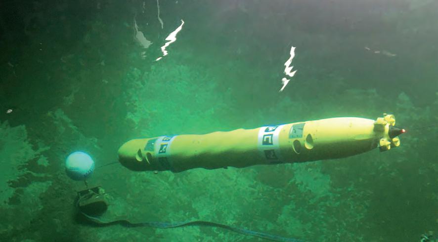
Basin experiments
After completion of the mAUV, the performance of the vehicle was assessed in a series of model basin tests. The advantage of testing in a basin rather than an outside location is that the environmental conditions can be controlled and access to the vehicle between tests is very easy.
After connecting the control system, all vehicle hardware components were carefully checked and all communication connections were tested. Then, a series of experiments were carried out in MARIN’s Seakeeping and Manoeuvring Basin (SMB). The first was a set of parameter identification tests, the objective of which was to determine the vehicle added mass and damping, as well as the maximum thrust values. These parameters were derived from the measured vehicle motions and the results were used to improve the accuracy of the vehicle’s digital twin. The second series of tests were operational limits tests to find the current performance limits of the vehicle. Maximum forward and transverse speeds were determined, as well as maximum rotational speeds. Furthermore, tests were carried out with the mAUV travelling at different drift angles. The last series of tests aimed to demonstrate possible applications of the mAUV. The demonstrations included manoeuvres that represented a mine inspection mission, a lawn mower pattern for a survey mission, a fast spiral, vertical positioning with the nose above water and a quay wall inspection.
A demonstration day was organized at the end of the test campaign, attended by representatives from various companies in the Dutch maritime sector. The many interesting discussions resulted in new ideas for potential applications of the vehicle and further research.
future deVelopments
The mAUV is currently capable of following a predefined track, defined in six DoF. For real autonomous operation, however, additional capabilities need to be developed. Several topics are on MARIN’s research agenda, including relative navigation for precise navigation near fixed objects (e.g. docking stations, underwater structures) or other vehicles (e.g. moonpool for launch and recovery). These research efforts will involve hardware development, position estimation algorithms and vehicle control strategies. MARIN will also look at additional actuators for more efficient vehicle control at a higher forward speed. This will involve actuator design, vehicle control strategies and allocation algorithms. Lastly, sensor fusion and situational awareness algorithms will be used to investigate the performance of lower cost motion sensors. For certain applications, this may be an alternative to a navigation grade INS.
conclusion
MARIN has designed and built a modular Autonomous Underwater Vehicle (mAUV) for research projects in its model basins. The vehicle has unique control capabilities that may be applicable for different autonomous tasks in the maritime domain. The vehicle, its control system and its capabilities for autonomous operation will be further developed through ongoing coordinated research projects. MARIN actively seeks partners to continue developing the mAUV technology. Finally, it aims to assist industry parties in their vehicle developments, using simulation studies and basin tests that focus on vehicle design and optimization.
Videos
https://vimeo.com/403010822 (MARIN mAUV project)
https://vimeo.com/383961461 (lawn mower pattern)
references
- “Design of an Underwater Vehicle for use in Basin Experiments - Development of MARIN’s Modular AUV”, Hans Cozijn, Haite van der Schaaf, Bas de Kruif, Egbert Ypma (MARIN), IFAC-CAMS Conference, Daejeon, Korea, 2019.
- “Control Design for a Multi-regime 6-DOF Underwater Vehicle - Development of MARIN’s Modular AUV”, Bas J. de Kruif, Hans Cozijn, Haite van der Schaaf, Egbert Ypma (MARIN), IFAC-CAMS Conference, Daejeon, Korea, 2019.
Hans Cozijn
Hans studied Naval Architecture and Marine Engineering at Delft University of Technology. After 20 years of experience in hydrodynamic scale model testing and computer simulations of offshore structures, Hans moved to MARIN’s new Autonomy & Decision Support team to work on the development of autonomous vehicles.
Bas de Kruif
Bas de Kruif received his MSc and PhD in control engineering at the University of Twente, the Netherlands. He has been working between industry and academia ever since, and enjoys bringing cutting edge solutions to practical problems. For the last few years, he has been working on maritime applications within MARIN’s Autonomy & Decision Support team.
Haite van der Schaaf
Haite studied Electrical Engineering at the University of Twente. After his graduation, Haite started developing instrumentation, software and systems with a strong focus on Mechatronics and Measurement & Control technologies. For 20 years, Haite has held various positions at MARIN in the field of instrumentation development and project management.
Egbert Ypma
Egbert studied Naval Architecture & Marine Engineering at Delft University. After his military service in the Dutch Navy he worked for Heerema (working on simulations, DP systems), Imtech (Integrated Bridge & DP) and Global Maritime (DP, FMEA). He joined MARIN in 2005, where he worked in various departments. Since 2019, he has been team leader of the new MARIN Autonomy & Decision Support team and responsible for the similarly named research programme.
A New Way to Monitor Your Data
Automatic Calibration for MBES Offsets
Currently, calibration of MBES for hydrographic surveys is based on the traditional ‘patch test’ method. This subjective method, although rigorous, has major drawbacks, such as being time-consuming (both data acquisition and processing) and supposing that potential angle misalignments can be considered as uncoupled. A new algorithmic solution, providing an objective and repeatable first step to the automation of the calibration process, is offered through the MSPAC solution.
Hydrography is essential in many marine activities: • Ensuring navigational safety for nautical charts and dredging. • Acquiring accurate knowledge of environmental background for offshore installations and dredging. • Modelling the seabed for marine energy prospection.
Multibeam echo-sounder technology has evolved rapidly in recent years (multi-frequency, multi-swath, real time compensation, etc.), which has led to major improvements in spatial resolution and bottom coverage. To maximize benefits from these improvements, a careful calibration of the survey system has to be undertaken, but after the work carried out in the 1980s and 1990s that lead to the well-known patch test method, the subject has received limited attention. It is therefore time to move forward.
ClassiCal PatCh test
The patch test decouples the three boresight angles by surveying characteristic areas following a specific pattern. For the roll angle, a flat bottom is surveyed in opposite directions. For the pitch angle, a slope or a particular seabed feature is surveyed in opposite directions. The effect of yaw is classically determined by identifying a target over a flat bottom, and surveying it from two parallel and overlapping survey tracks heading in the same direction. As an example, Figure 1 sketches the configuration needed to determine the roll boresight angles.
While this method is particularly efficient, it has a series of drawbacks, such as: • Prior knowledge of the area is required. • Very accurate horizontal positioning is assumed. • Boresight angle estimation is operatordependent (manual data processing and morphology fitting). • No estimation is made of the precision of the resolved angles. • Only angles are resolved; lever arms are assumed to be correct. • Latency between the IMU and multibeam is not resolved.

Figure 1: Top view of the two reciprocal lines on the left and effect of roll boresight on two opposite lines on a flat seafloor on the right, from [1]. Figure 2: Geo-referencing equation for bathymetric data and the MSPAC software suite Shom.
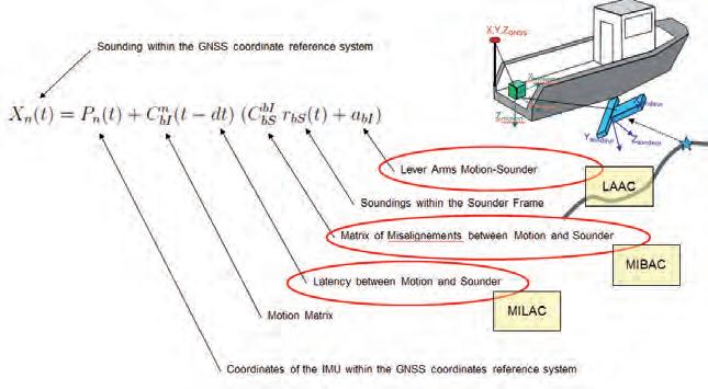
MsPaC solution
To address some of these shortcomings, a new calibration procedure has recently been developed by CIDCO, Shom and ENSTA Bretagne. The ambition is a new robust and objective methodology that provides a solution for the boresight angles and the latency and lever arms estimation, based on a specific data selection procedure for a plane-robust least squares adjustment model. This solution also saves time during acquisition and processing. Figure 2 details the classical geo-referencing equation of bathymetric data as well as the quantities that MSPAC (Multibeam System Parameters Automatic Calibration) aims to resolve using three sub-modules: MIBAC (Multibeam IMU Boresight Automatic Calibration), LAAC (Lever Arms Automatic Calibration) and MILAC (Multibeam IMU Latency Automatic Calibration).
results anD Distribution
The results of these algorithms are presented in detail in articles [2] and [3]. An example of the data selection made by MIBAC is shown in Figure 3. In this figure, the seabed is modelled as a grid of surface elements. For each element, a sensitivity criterion is calculated to indicate areas where boresight angles cause the most distortion of the seabed.
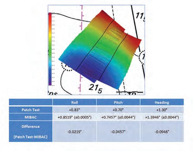
Figure 4 shows the results of the comparison between a traditional patch test and MIBAC. These results have been freely distributed, so that everyone can experiment with and test these algorithms. The study reports (under ‘licence ouverte’/, a French open license) and the source codes (under CeCILL license, GPL compatible license) can be found at gitlab.com/ GitShom/mspac/shom-mibac. The Shom disclaims any responsibility for the operational transfer as well as the maintenance of this software. Stakeholders are of course invited to use, improve and industrialize these source codes.
inDustrialization
The software is being continuously improved by the open source community to allow customizations of various aspects such as: • Total propagation of uncertainty. • Planar surface element detection. • Least squares estimation. This will allow, for example, the incorporation of different methods for identifying planar surface elements, such as [4]. Several internal parameters are currently inaccessible to the user, such as: • Iterative thresholds. • Statistical test parameters. • Planar surface elements modelling.
As with all open source endeavours, the code can be parameterized to suit customer-specific needs either by CIDCO or third-party developers. The current state of MSPAC is only available from a command line interface and a graphical user interface would greatly improve the user experience. We welcome this initiative to publish MSPAC codes under open source licences and we look forward to working with stakeholders and members of the open source community on further developments of the MSPAC calibration suite.
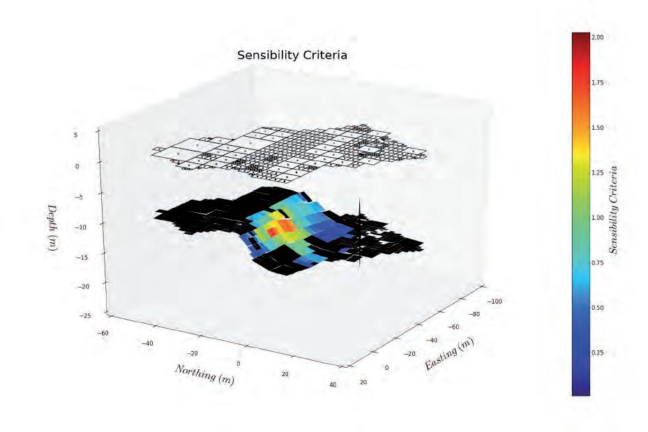
Figure 3: MIBAC data selection on a real dataset, from [1].
Figure 4: Above, EM2040c Brest harbour survey strips in order to compare the methods (the DTM highlights the angular misalignments over the overlap area). Below, the difference between patch test and MIBAC offset values on these survey strips.
ConClusion
The automation of the calibration workflow is an essential step in the droning of acquisitions at
sea. Even if the results seem very interesting, it is also necessary to have a good quality positioning source (RTK or PPP) and a bottom morphology corresponding to a gentle slope to obtain the best results. In addition, the proposed solution makes it possible to provide a statistical uncertainty on the measurement as well as an objectivity that is diffi cult to achieve with the classical patch test. It also makes the automation of calibration procedures possible, especially for drones. The contact person for the MSPAC solution industrialization is jordan.mcmanus@cidco.ca.
Acknowledgements
This solution was developed through a NOCALIT/CALIB-1 research project between ENSTA Bretagne and Shom with funding from DGA (French Ministry of Defence). Thanks to DGA for supporting this project and for making it possible to disseminate these results.
Further Reading
- [1] Le Deunf, J., 2015. Data selection for a boresight estimation algorithm. Master thesis report.
- [2] Keyetieu, R., Seube, N., Multibeam Echo Sounders-IMU Automatic Boresight Calibration on Natural Surfaces. Marine Geodesy, Volume 40, 2017, pp 172-186.
- [3] Keyetieu, R., Seube, N., Djine, V., Roue, G., Clement, B., Bosser, P., 2018. Multi-Beam Echo Sounders–INS Automatic Latency Calibration. Marine Geodesy, Volume 41, 2018, pp 477-493.
- [4] V. Dupont, S. Daniel and C. Larouche, “A region growing algorithm adapted to bathymetric point clouds,” OCEANS 2019 MTS/IEEE SEATTLE, Seattle, WA, USA, 2019, pp. 1-6. DOI: 10.23919/ OCEANS40490.2019.8962821 Michel Legris, Eng, PhD, is an Associate Professor at École Nationale Supérieure de Techniques Avancées Bretagne, Brest, France. After working for several years for the French Ministry of Defence, he now teaches underwater acoustics and inertial navigation. His research interests are high frequency sonar and AUV localization.
Jordan McManus, programmer analyst at CIDCO. Graduated in software engineering from the University of Ottawa in 2006. Specialized in physical oceanography and software development related to remote sensing and hydrographic data processing. jordan.mcmanus@cidco.ca
Julian Le Deunf is a French hydrographic category A engineer. After graduating in 2015 from ENSTA Bretagne, where he completed a six-month internship at CCOM (UNH, US), he started at Shom as a survey team leader (in Cameroon, Gabon, Mauritania and France). He is now an expert in bathymetric data processing at Shom and is focusing in his PhD on this topic. julian.le.deunf@shom.fr


NEW miniIPS2 & uvSVX The next generation of interchangeable pressure sensors

Valeport has launched the new miniIPS2 and new uvSVX which both offer operationally specific interchangeable pressure transducers that deliver enhanced accuracy for specific depth ranges.
These field-swappable sensor heads make it easy for users to select the correct pressure range for their work and offer increased accuracy at any depth.