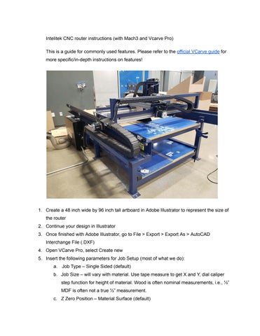
Intelitek CNC router instructions (with Mach3 and Vcarve Pro)
This is a guide for commonly used features. Please refer to the official VCarve guide for more specific/in-depth instructions on features!
1 Create a 48 inch wide by 96 inch tall artboard in Adobe Illustrator to represent the size of the router
2 Continue your design in Illustrator
3 Once finished with Adobe Illustrator, go to File > Export > Export As > AutoCAD Interchange File ( DXF)
4 Open VCarve Pro, select Create new
5 Insert the following parameters for Job Setup (most of what we do):
a Job Type – Single Sided (default)
b Job Size – will vary with material Use tape measure to get X and Y, dial caliper step function for height of material Wood is often nominal measurements, i e , ½” MDF is often not a true ½” measurement
c Z Zero Position – Material Surface (default)
d XY Datum – Change to the upper right dot (this is close to Machine Reference Zero, the corner closest to the cafeteria doors) Ensure the “use offset” button is NOT checked <<< make extra sure of this It sometimes gets checked and I don’t know why
e Modeling Resolution – Standard, but will vary
6 Click OK
7 Under File Operations, click the “Import Vectors” folder (top row, 4th over)
8 Select the DXF file you created in step 1
9 Use the options in Edit Objects to manipulate your vector’s placement
a Ensure you leave about 2” from where ever you will be clamping your material so the spindle/tooling doesn’t chop off the clamp
10 In the top toolbar, select Toolpaths > Show Toolpaths Tab
11 Before selecting toolpaths, ensure the entire vector is black, not dotted pink
12.Working from the inside of objects to the outside, select a shape/vector and it will highlight it with dotted pink
13.Under Toolpath Operations, there are several cutting options for your cut. Profile and pocket are 99% of our cuts.
a. Profile - simple cutting. You can cut inside or outside of your shape, or on the line. Typically, cutting a shape out, you would choose “outside/right.” For a shape within an object, you would do “inside/left). It is rare to choose “on” the line. When in doubt, ask the instructor.
b. Pay close attention to how your pieces will fit, tolerance them appropriately
c When you are done with a toolpath, you must click off of the shape otherwise it will remain highlighted and potentially mess with the next toolpath
14 Once you have set your toolpaths, click “Calculate” and read any pop-up messages
15 The next toolbar that pops up will allow you to preview your toolpaths in animation
16 Once satisfied, click “Close”
17 Click the save disk icon in the Toolpath Operations menu (bottom right icon)
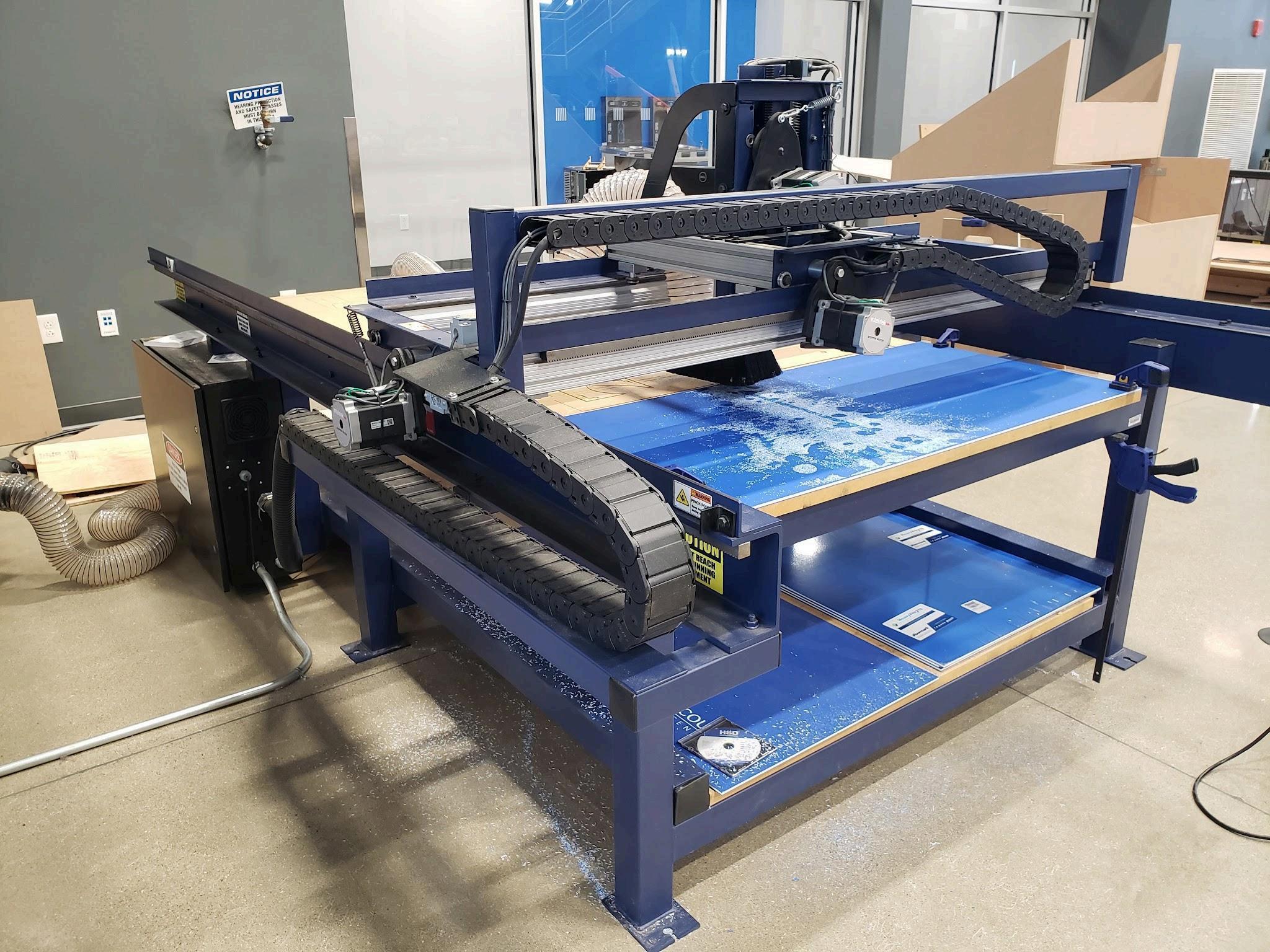
18 You will be at the Save Toolpaths menu
a. Ensure the list of selected toolpaths (check box) at the bottom is the order in which you want to cut (pockets first, inner cuts, then outer cuts last). You can drag and drop them where you want to place them.
b. If you are using the same tool for all toolpaths, you can select “visible toolpaths to one file ” If you want to save/run each file separately, select “visible toolpaths to multiple files ” If you only want to run what you have checked, click “selected toolpath”
19 Click Save Toolpath(s) to save the toolpath file ( tap) to a USB drive
a This is called a “post-processor,” and similar to a slicer in 3d printing It communicates the CAD design into G code for cutting
b Be specific in naming it so you know what the cut is, and sequence for it
c Be careful of your sequences Most of the time, you will work your way from the insides to outsides Pockets first, inside cuts second, outside cuts last
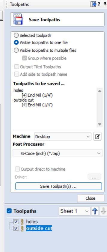
20 On the CNC router, turn the green button to the on position
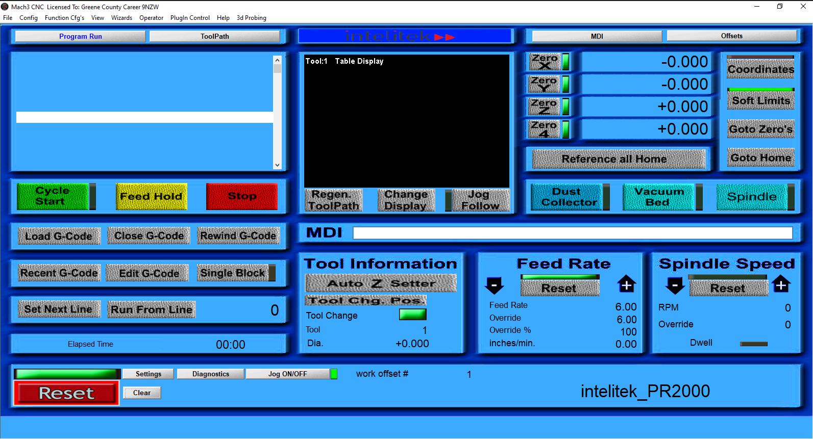
21 Open Mach3 on the small Dell computer
22 Click Ok on the Session Profile popup window
23 Click Reset to clear the alarms (lower left part of screen)
24.Using keyboard (arrows for XY, pg up/pg dn for Z, hold shift for faster movement), raise the Z a few inches off the board, and jog XY to the corner closest to the lab cafeteria
doors If you don’t do this, step 21 will take a few minutes to accomplish
25 Click “reference all home” in Mach3 to reference the machine (machine reference zero, MRZ)
26 To secure your workpiece
a If using a 4’x8’ board, use a two-person lift to put it on the table
b Square up material to the machine reference zero (MRZ) corner
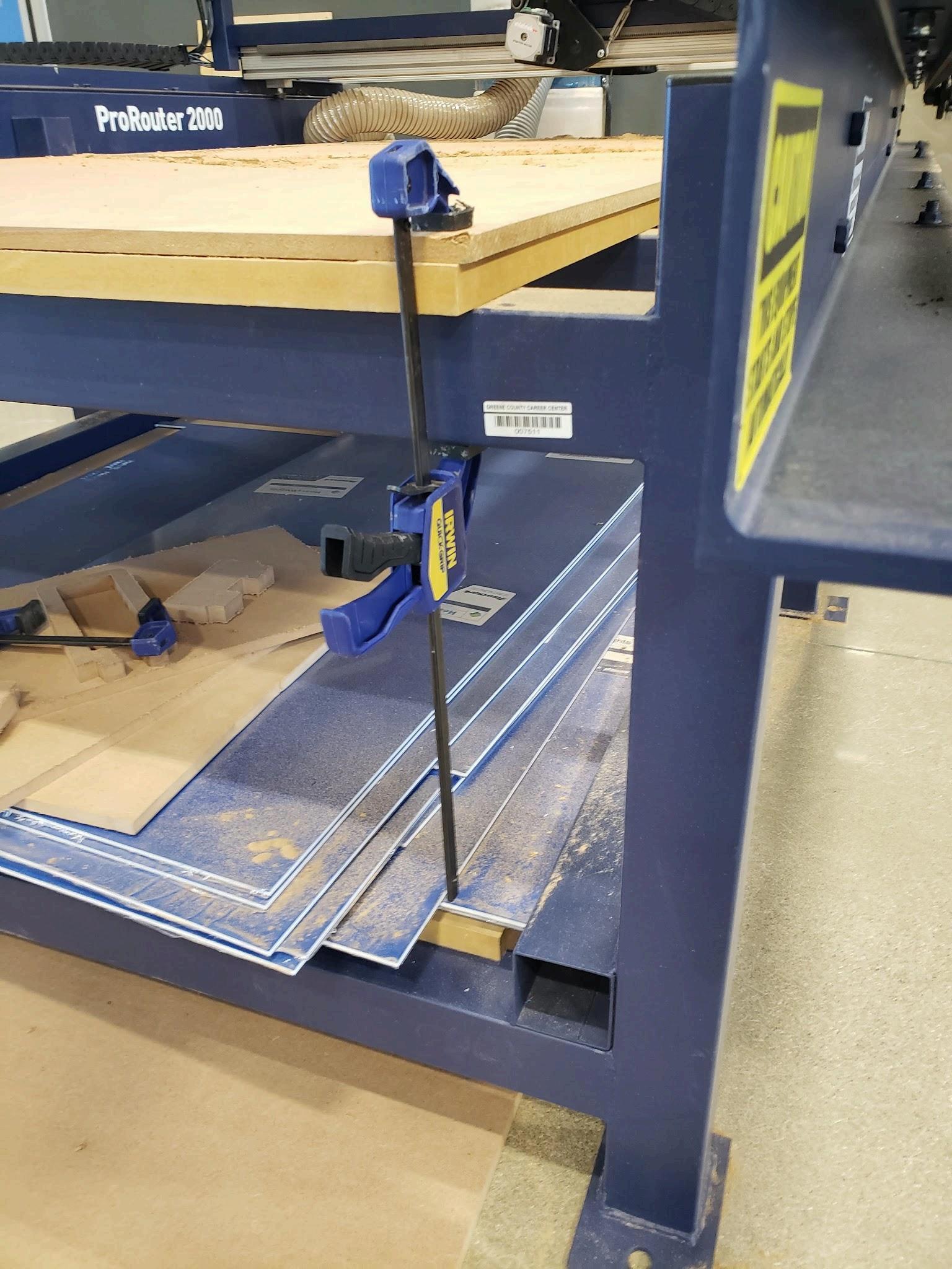
c Use blue plastic jawed (not metal) clamps at varying points on the material - try to avoid the MRZ as the spindle will crash into it Also, avoid areas where work will occur You may have to use a tape measure to make sure you don’t accidentally hit the clamps Ensure the metal bars on the clamps are pointing toward the ground otherwise they will interfere with the gantry
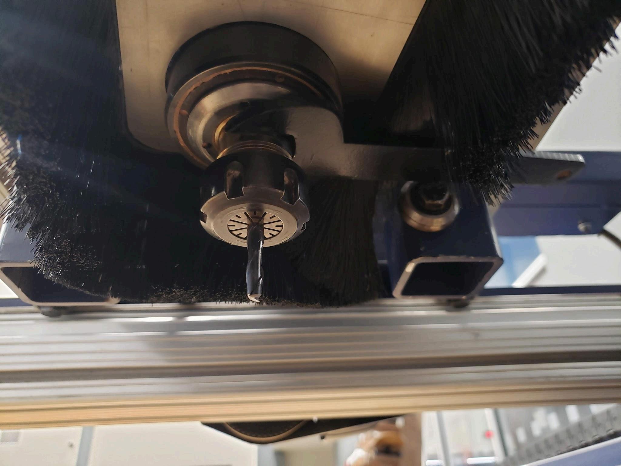
27 To change tool
a. Click “Tool Change Pos” button on Mach3
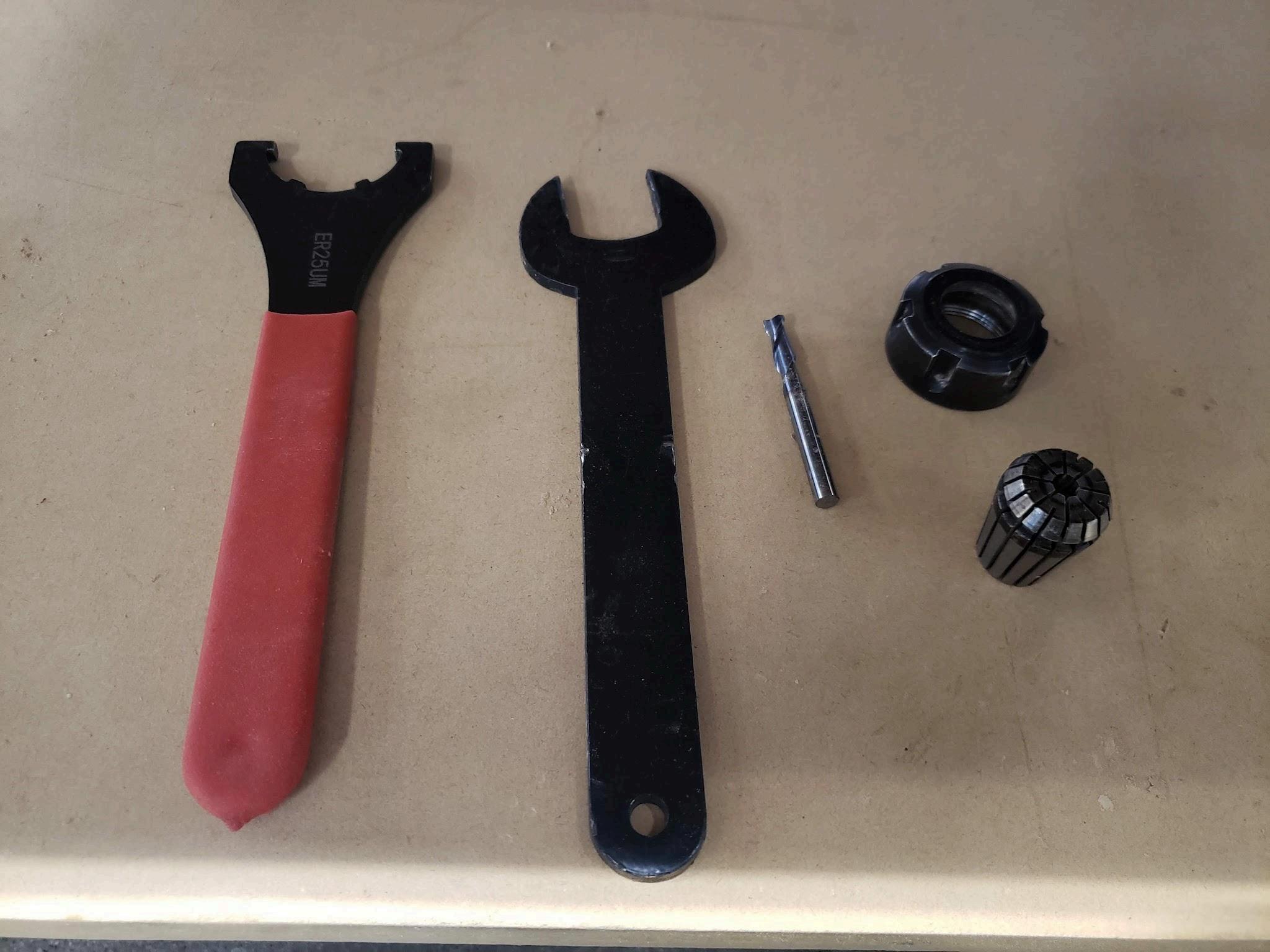
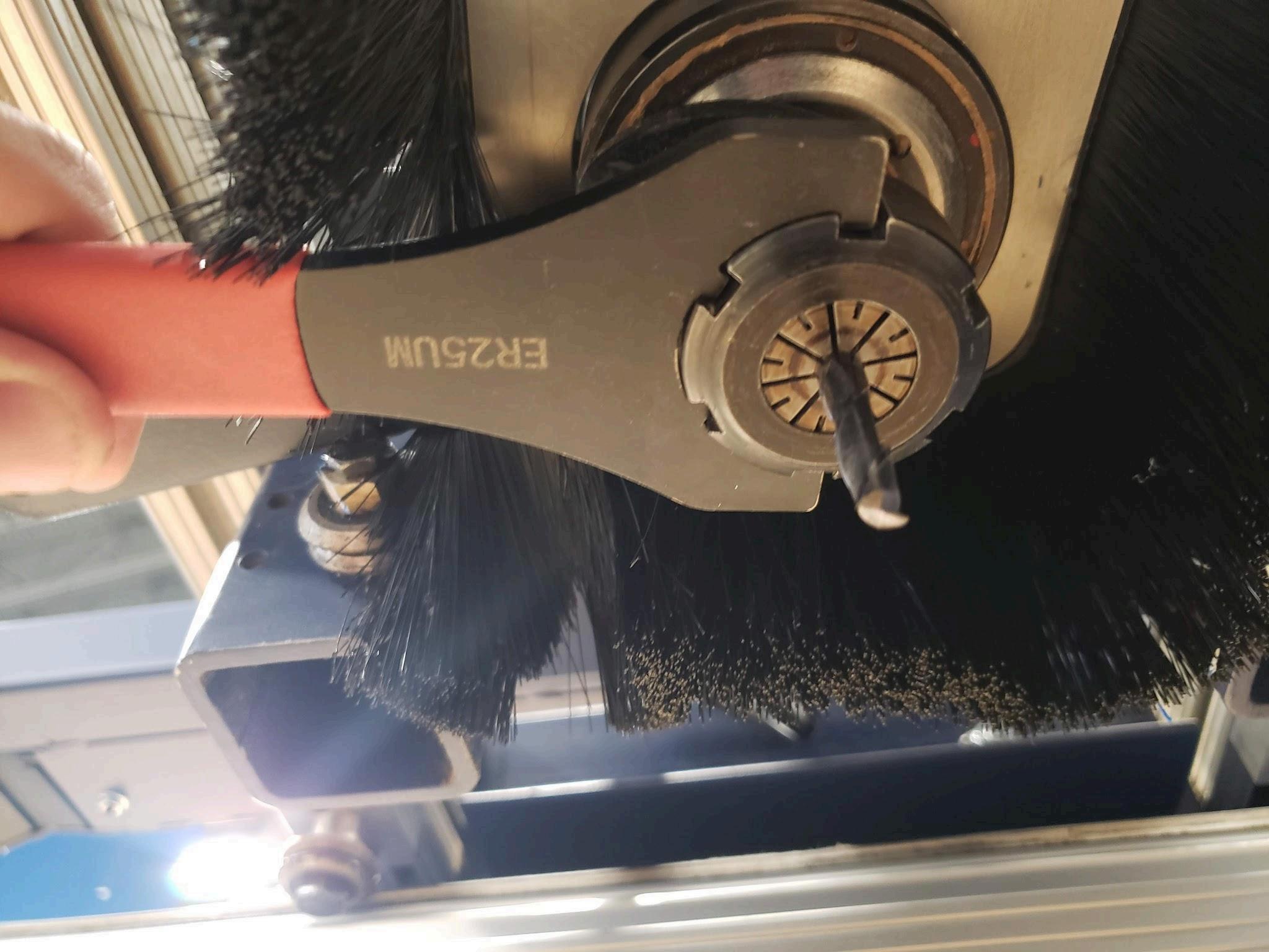
b. Locate spanner (black crescent wrench), collet wrench (red handle, notches in opening), collet, tooling, and collet nut
c If tool is already loaded, we need to remove the collet nut, collet, and tool to install a different tool if needed
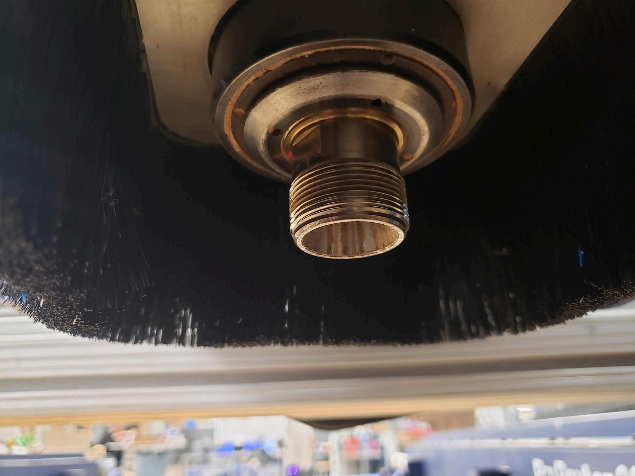
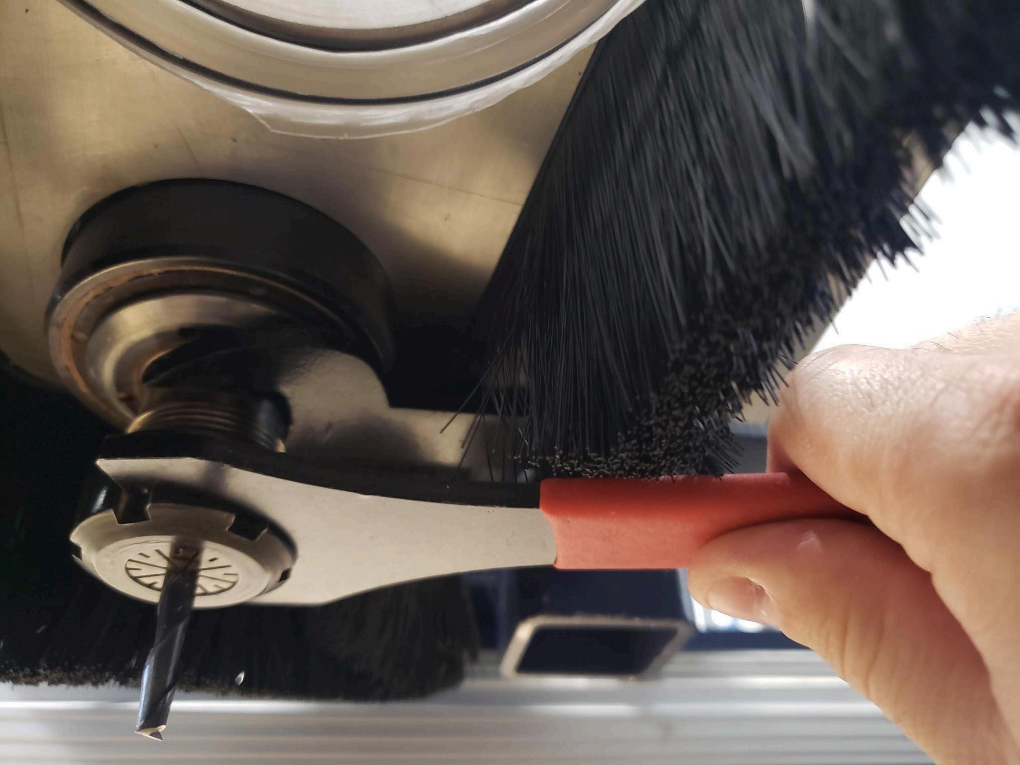
d To remove, place black crescent wrench on the spindle - it is notched - and turn it to the left and rest it on the gantry nut During step e It must be stable and not moving
e Place collet wrench on the collet and turn to the left to loosen the collet nut Once loosened be careful of the tool falling out
f. Remove collet nut from spindle
g. Remove black wrench
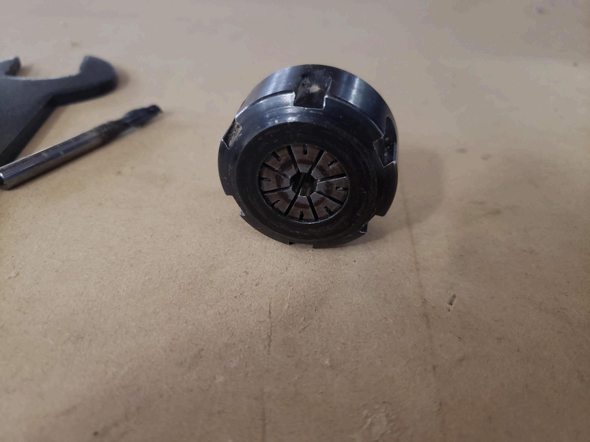
h. Tap center of collet to remove from collet nut
i. Install new collet in the collet nut - you may have to tap with mallet, but it will click in
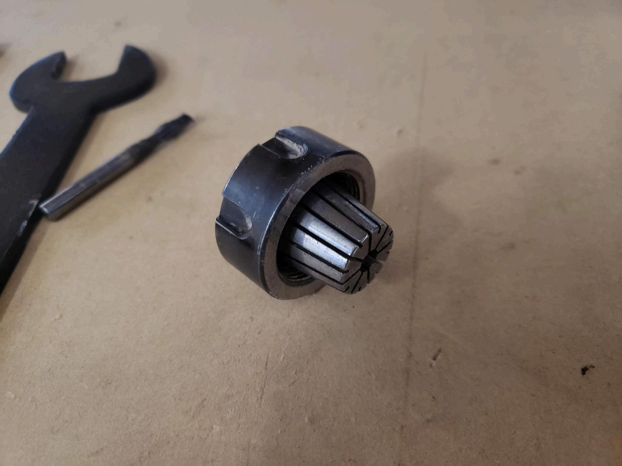
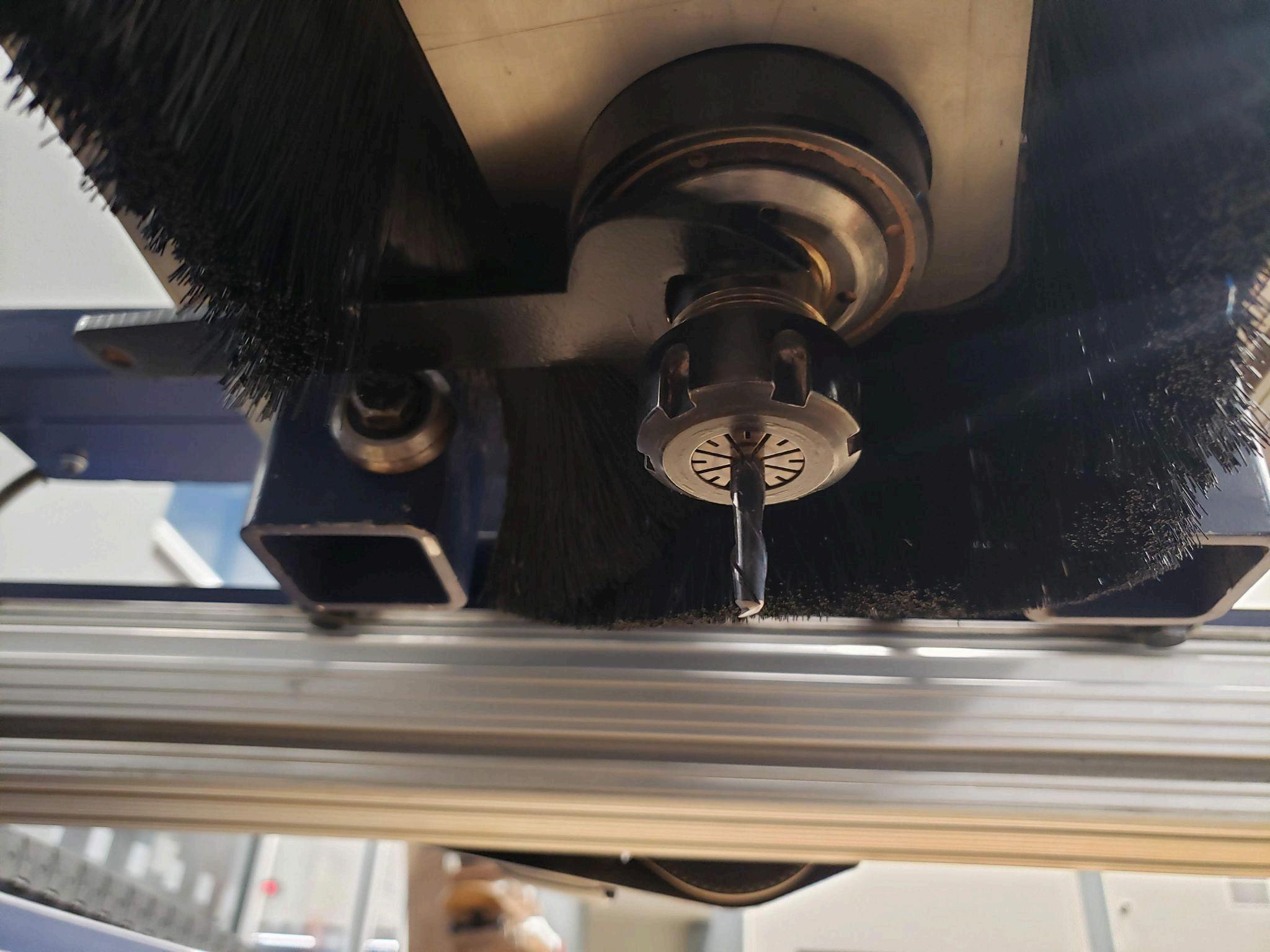
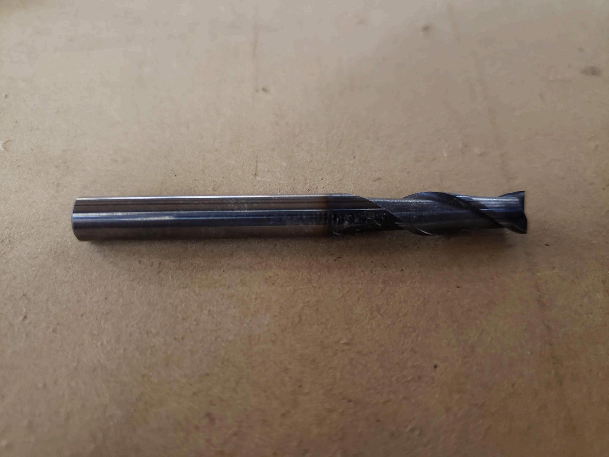
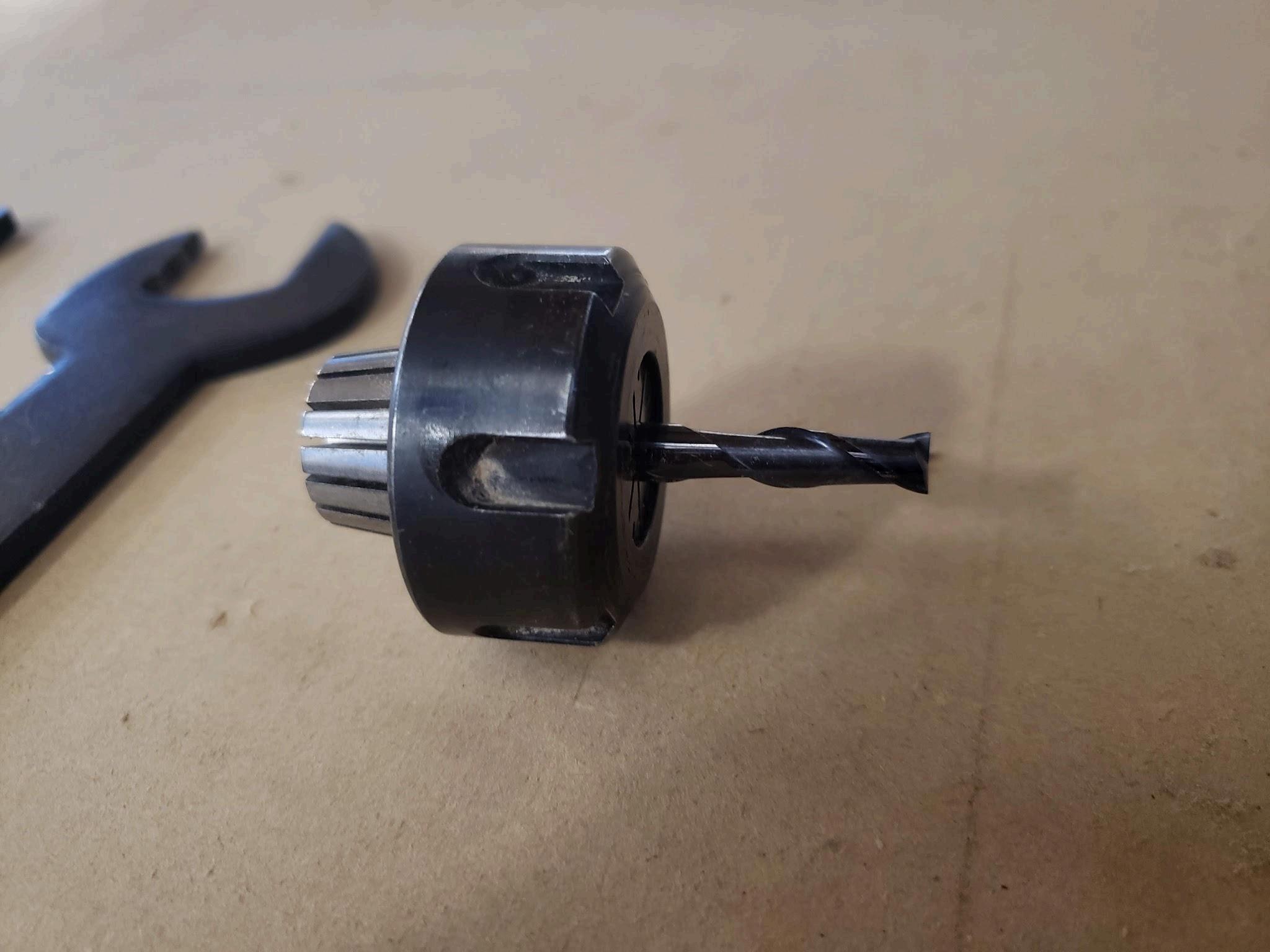
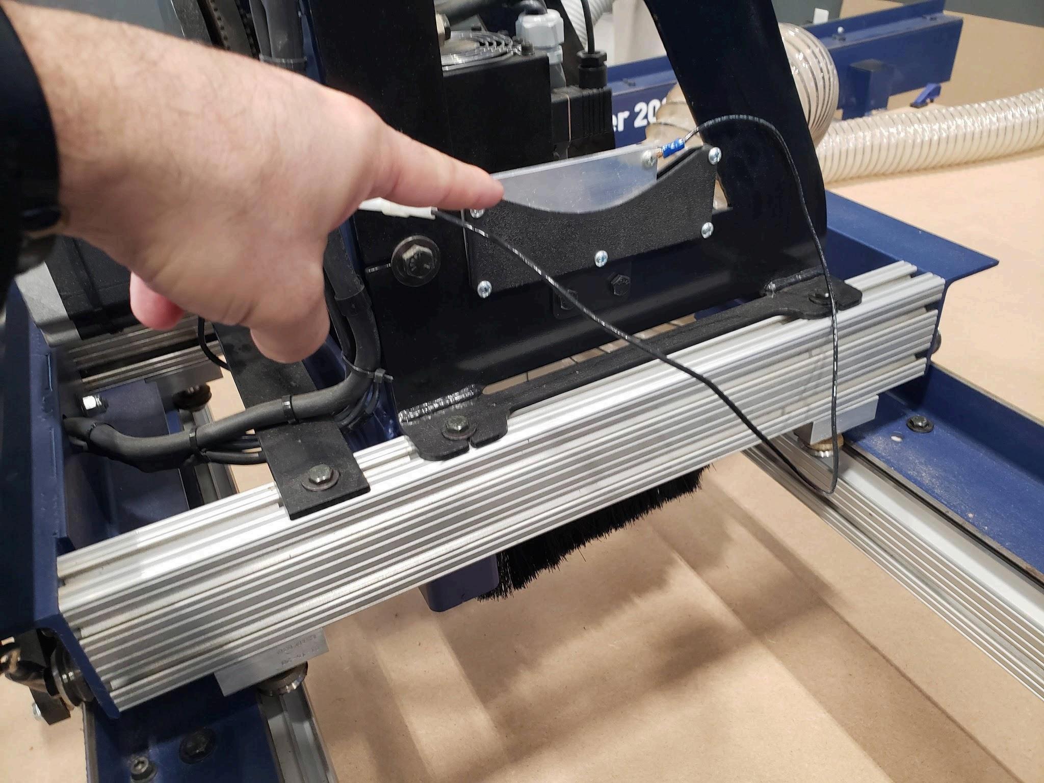
j Place tool inside collet - most of shaft should be inside collet for a stable fit
Ensure the cutting surface (flutes and channels) are not inside the collet See picture below for reference The tool should fit snug into the collet and not wiggle around If it wiggles around, you will need a smaller diameter collet
k Place black wrench back on spindle, this time align to the right side and rest on gantry nut
l. Screw collet nut to the spindle hand tight to ensure the tool doesn’t slide out
m. Use collet wrench to turn collet nut - turn to the right
n. Remove both wrenches
o Note - every time you change a tool, you must zero your Z axis
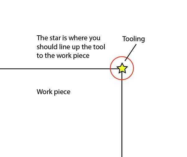
28 Zero your part
a Align part to the corner closest to cafeteria doors (MRZ corner)
b Move XY axis to the corner of the workpiece You will need to lower the Z axis to see where the tool is on the material, and it’s easiest with a spotter
c. To zero Z axis (any time you change tools and/or work pieces) jog spindle closer to where you can reach it, but over material
d. Place the wired metal plate under the spindle/tool
e. Click AutoZ setter to zero the Z axis. The spindle will slowly move down toward the material. Once it touches the plate, it will establish a continuity loop that will zero the Z axis automatically and return the spindle up.
f. Return the wired metal plate to its housing
29.Insert USB drive with the .tap file into the small Dell computer
30.Click load g-code in Mach3
31.Find your .tap file on the USB drive where ever you saved it
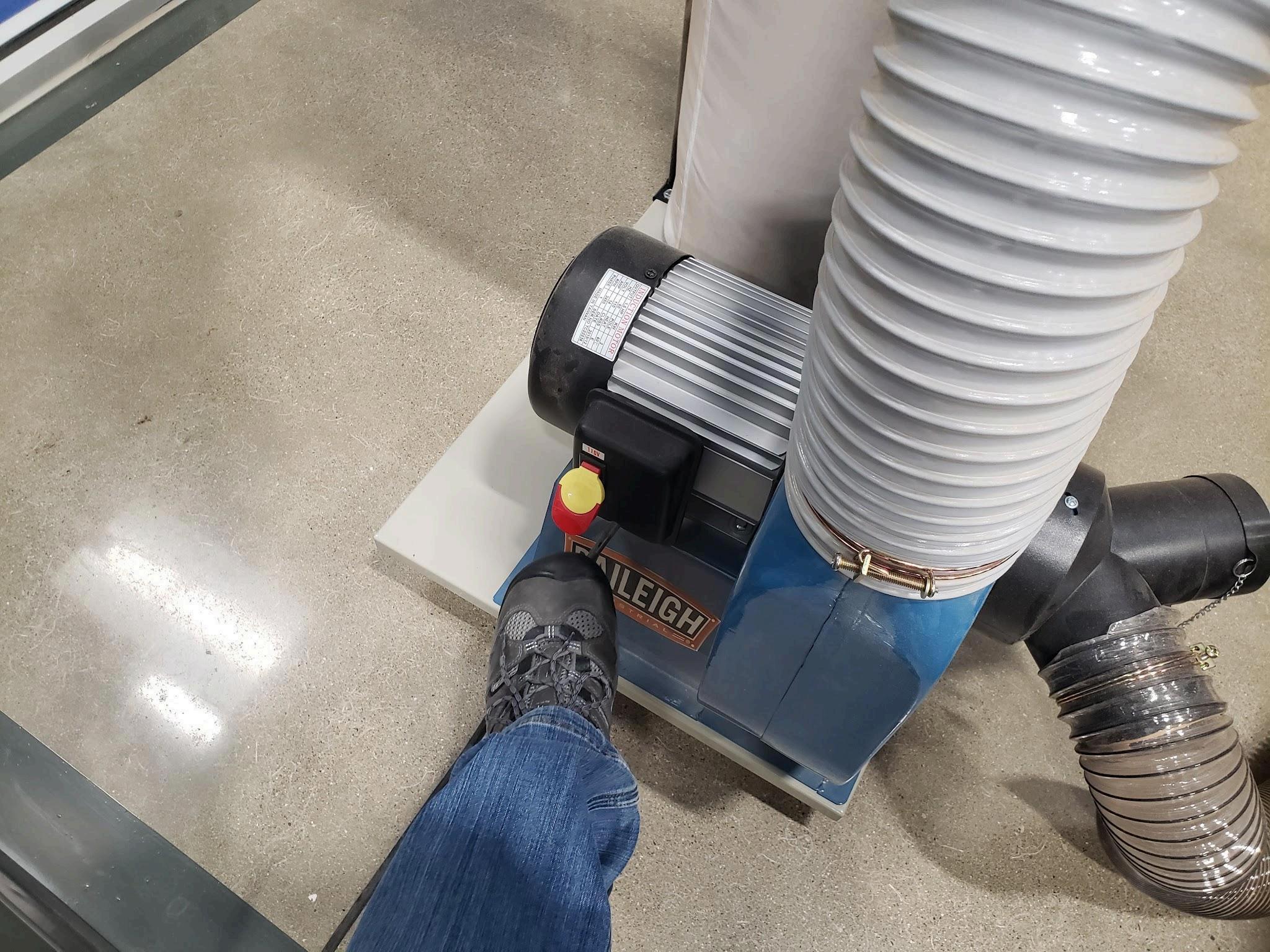
32 Turn on the dust vac
33.Click “Cycle Start” to begin the cut
a. If you get a “soft limit” warning, this means the toolpath exceeds the dimensions of the router and must be reconfigured Check your X0Y0 (home) to ensure it’s at the MRZ corner If it is, check your toolpaths in VCarve as they may be too close
34 T
35 T
d If the G Code is closed, reload it and scroll down the lines until you get near your step number from step b If G Code was already loaded, scroll up until your steps are lower than where it stopped You can start below the step number, but not after it For instance, if you stopped at step 500, Rewind G Code to step 450ish
e Click Run From Line
f. Click Cycle Start
g. Confirm the Preparation Positioning pop up by clicking OK (don’t worry about checking boxes) this will move the spindle/XY in place
h. Click Cycle Start again to begin cutting