
HUMAN FACTORS
MATERIALIZING MACHINES


Tutors
Alicia Nahmad
Federico Borello
Team
Gaurav Janendra
Jamil Al Bardawil
Jonatan Zisser
Sitong Liang
In this workshop, we had to design furniture for hot wire cutting, which involved dealing with the various constraints, in the process of achieving a final model for fabrication.
This booklet showcases the design process that we developed in the workshop. We spent the initial weeks designing geometry based on the ruled surface principles and later on developed these principles to tackle a complex set of operations to achieve a three-dimensional volumetric model. Following the same design DNA matrix, we managed to develop a model for fabrication considering all the restraints involved in dealing with robots. Finally, with the usage of the model, we were able to iterate multiple compositions without compromising the functional aspect of the module. Overall, this entire process had to be repeated multiple times, to achieve a model that runs smoothly for hot-wire cutting.

INTRODUCTION
RULED SURFACES
A ruled surface is defined by the property that through every point in the surface, there is at least one straight line which also ties in the surface. A ruled surface may be thought of as one “swept out” by a straight line moving in space. To describe how such a line moves, first recall that any line is uniquely determined by two distant points which lie on it. Then by choosing two curves, and a suitable map between their points, we can join up points with lines in order to define a ruled surface.

https://slideplayer.com/slide/16349625/ https://www.researchgate.net/figure/Examples-of-hand-drawings-a-parallel-projection-of-ruled-surfaces_fig2_280623703
CONSTRAINTS
The design process evolved in dealing with multiple constraints from the robotic hot wire cutting process. Two major constraints were, the bounding box dimensions and the comfort of the robotic arm movement. These constraints were primarily to deal with the path in which the robot had to initiate the cutting process. After a series of experiments and alterations, we were finally able to achieve a form that was flexible for hot-wire cutting.
Realizing that many parts of the negative volume are treated as waste, we wanted to develop a model wherein the negative leftover mass could further be utilized for fabrication. So, the overall mass of the bounding box can be used efficiently.
The entire design process was focussed primarily on delivering a model which can be used most efficiently, and also resolves all the constraints set out by the robot for hot wire cutting.

FEEDBACK LOOP

CONSTRAINTS
PRIMITIVES
GEOMETRY
STUDY
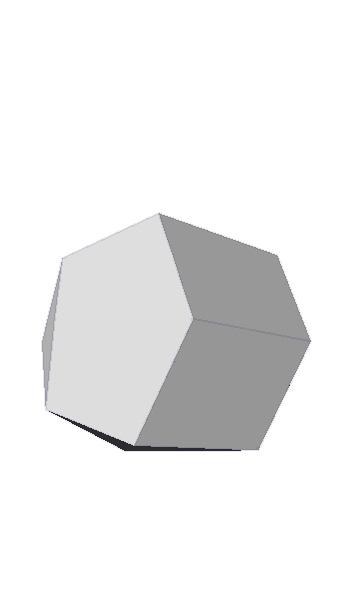
The design development began by understanding the various base primitives and the operations that follow them.


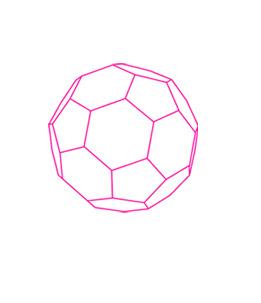
CYLINDER E: 20 | V: 11 | F: 11 SOCCER BALL
90 | V: 60 | F: 32

PRISM
18 | V: 12 | F: 8
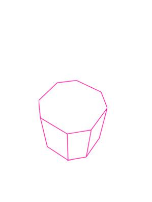
PRISM

24 | V: 16 | F: 10 BEVEL
Value: 0.25 Value: 0.25 Edge Loop No: 3
CHAMFER VERTICES SUB-DIVIDE SCALE

EXTRUDE FACES
CLARK (S mooth)
DESIGN OPERATIONS
From understanding a set of base primitives and the operations, we developed a formal language that could be further used for achieving a three-dimensional volume.


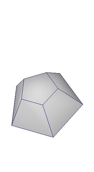


PENTAGONAL PYRAMID


FURNITURE DESIGN
The primitive studies led us to develop a series of furniture models that followed a similar set of operations. Simultaneously, we had to constantly run these models in the robotic hot wire cutting program, to ensure that these models follow the constraints set out by the robot. By doing so, this study allowed us to understand each model’s capacity in confronting the various constraints that we were aiming to deal with it. After a series of operations, the comparision table explains the inference that we were able to derive from this study.


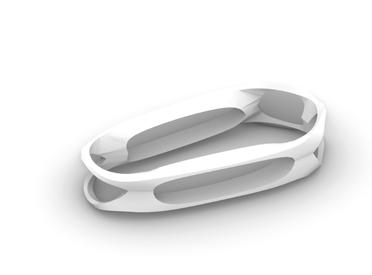

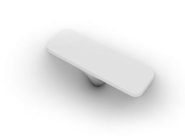

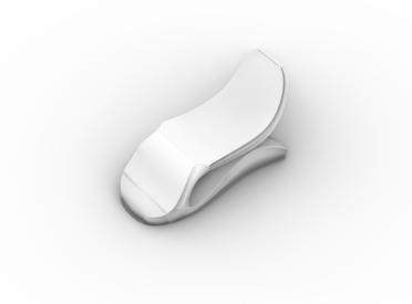

CUTTING EFFICENCY
WASTE MANAGEMENT
As the no. of cuts were more, these two iterations were not efficient
COMPOSITIONS + ALTERATIONS
Since a lot of negative volume cannot be used, therefore, this set doesn’t manage to fit into the zero wastage target.
Has lesser no. of cuts and therefore the efficiency is much better compared to the previous two iterations.
Has lesser no. of cuts and therefore the efficiency is much better compared to the first set.
Has lesser no. of cuts then the first set, but has more no. of cuts then the second and third set
Similar to the previous set, a lot of negative volume cannot be used. Therefore, this system doesn’t manage to fit inot the zero wastage target.
Even this set cannot satisy the target for zero wastage strategy
Most part of the negative volume can be used and is better then the previous sets.
Some parts of the negative volume can only be used. Therefore, less efficient.
The two models in this set don’t allow for further compositions and alterations. Only one iteration is possible within one module.
Even though these models allow for multiple compostions but still it fails to deliver multiple alterations. They are better when compared to first and fourth set.
Even though these models allow for multiple compostions but still it fails to deliver multiple alterations. They are better when compared to first and fourth set. Allows for multipe compositions and iterations
These two models offer very limited alterations. Also, they don’t offer multiple compositions.

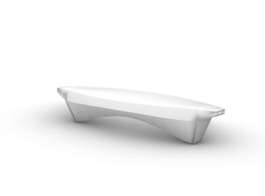
SELECTION
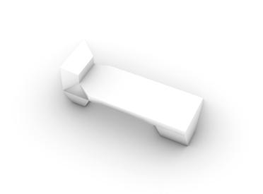
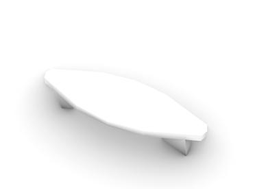
From the study inference and the design of multiple iterations based on the DNA developed, the selection of the model was through analyzing each model on how they met the requirements set out in the design process and how each model tackled the various constraints. Through the evaluation of each model, we started narrowing down the choices to decide on proceeding with the bench since it satisfies all the conditions set for the experiment to be successful, from waste management to composition, as well as the cutting efficiency and the robot comfort.
The fabrication process will show how this model met the standards we set as well as how we used the feedback loop from the robotic testing to further refine the geometry.


INTRODUCTION
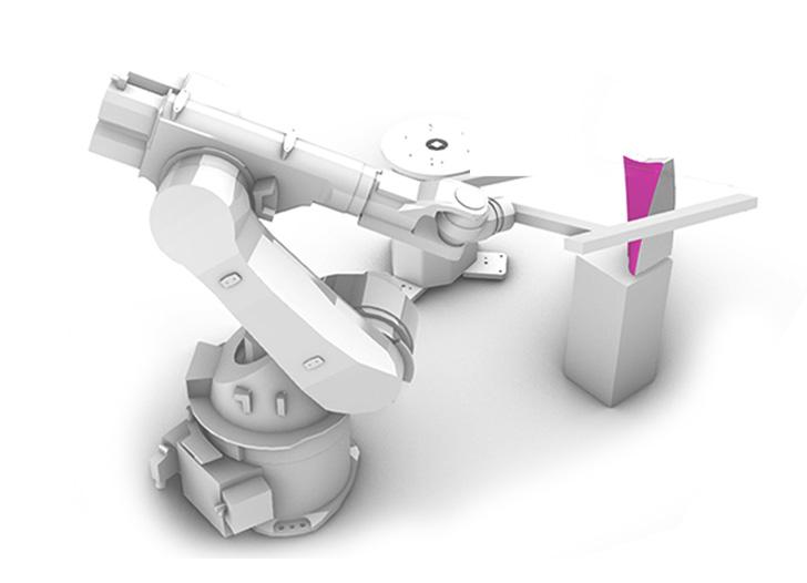
ROBOTIC HOT - WIRE CUTTING
Hot-wire cutting is a subtractive fabrication technique used to carve foam and similar materials. Conventional machines rely on straight wires and are thus limited to creating piecewise ruled surfaces.
While this setting offers great freedom of shape, using it effectively requires concurrent reasoning about three tightly coupled sub-problems
- Modeling how the shape of the rod and the surface it sweeps are governed by the robot’smotions
- Approximating a target shape through a sequence of surfaces swept by the equilibrium shape of an elastic rod
- Generating collision-free motion trajectories that lead the robot to create desired sweeps with the deformable tool.

http://crl.ethz.ch/papers/hotwirecutter.pdf
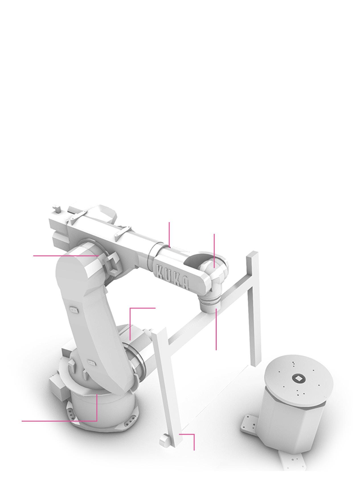
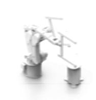
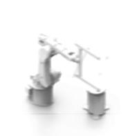
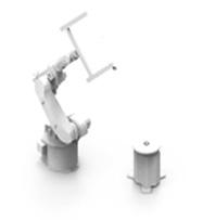
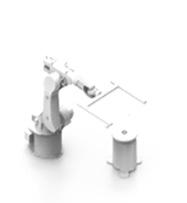
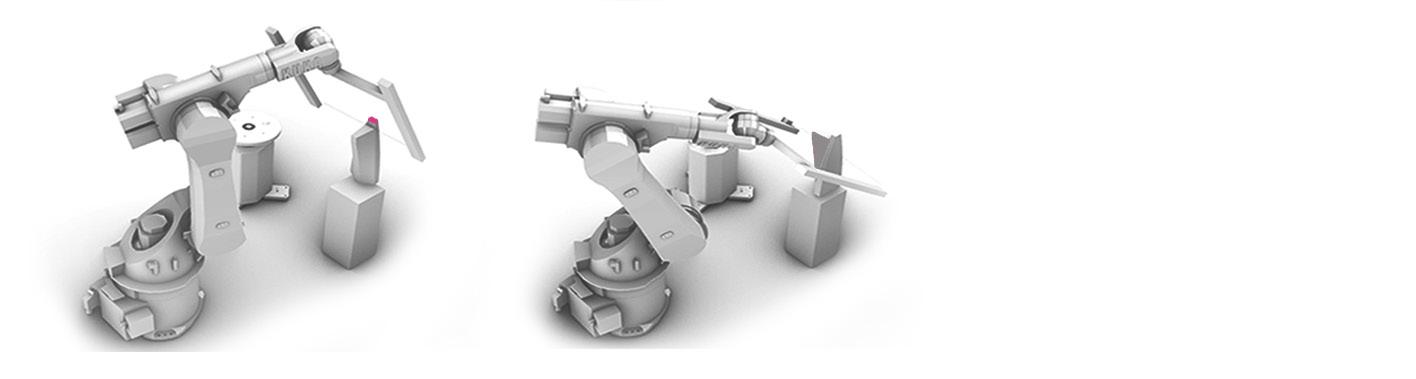
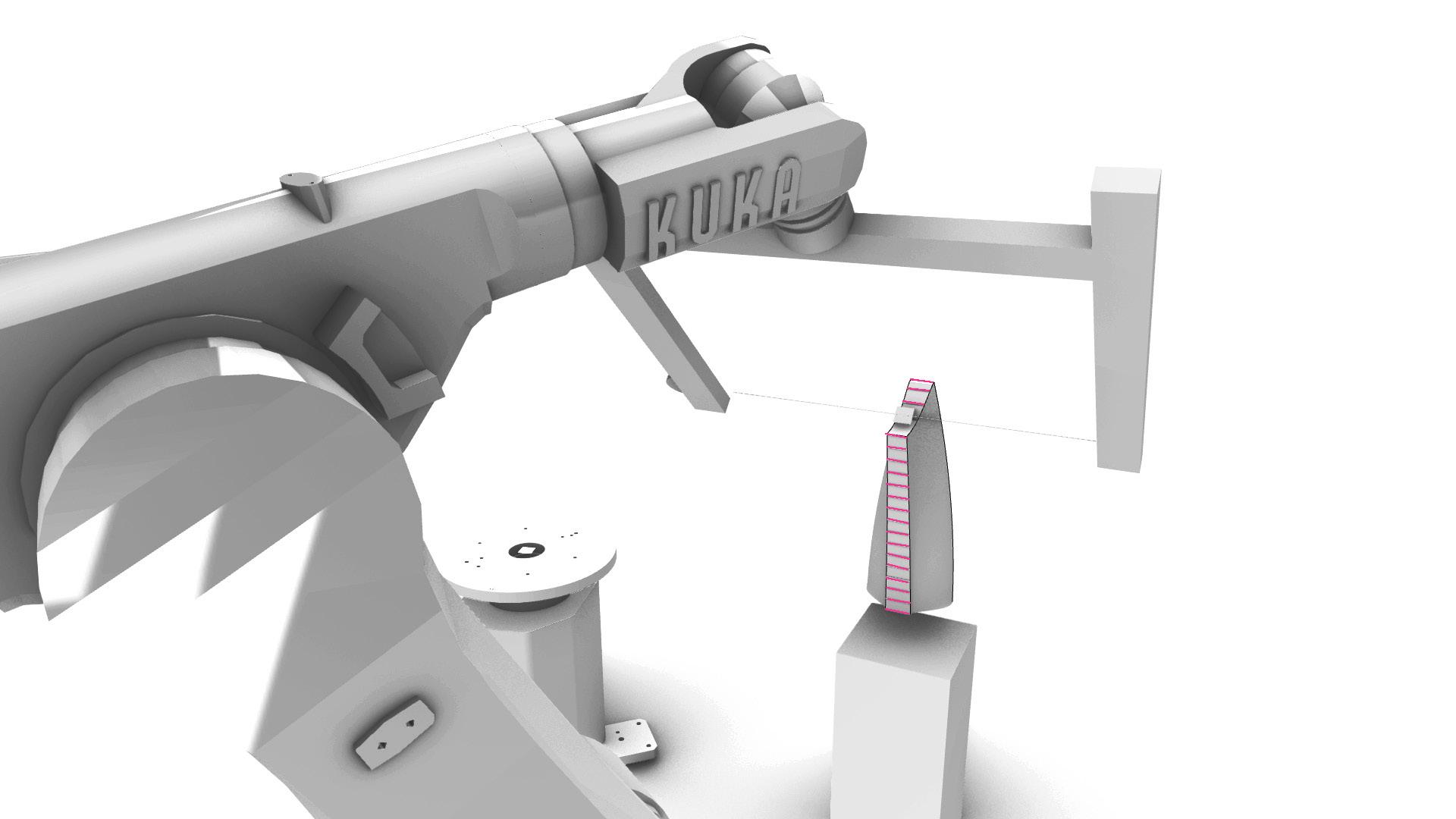
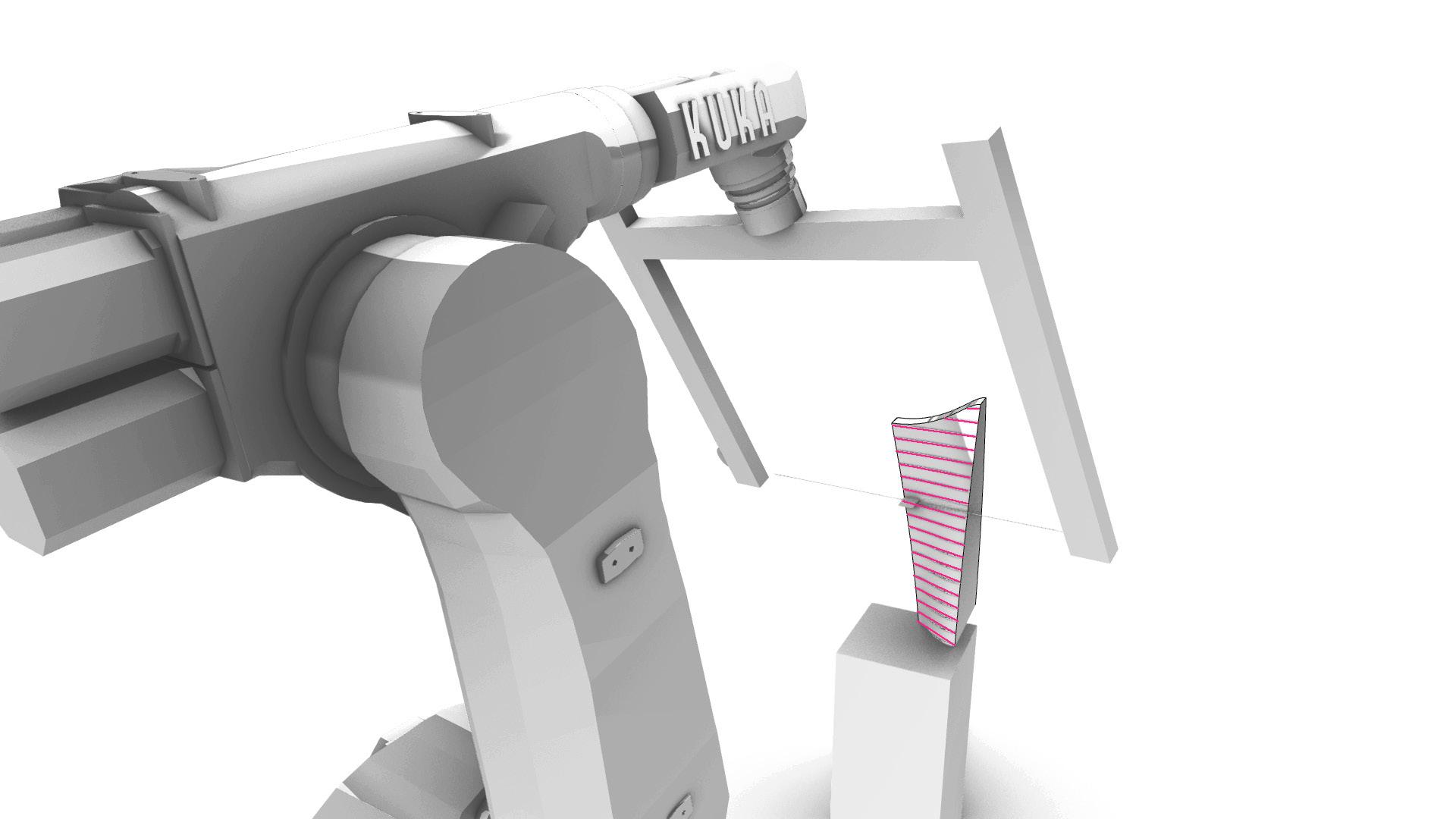
The robot we are using is the KUKA-60. The diagram below shows the rotation axis of the robot as well as the motion catalogue that shows how each axis operates.


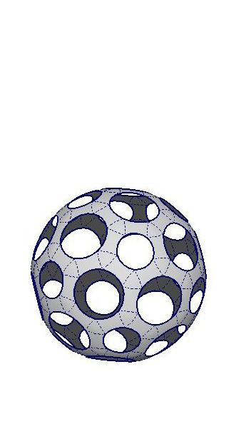
The first test was of half the final module that was taken to fabrication.
This diagram shows the cutting sequence of the first test and the number of cuts


After experimenting we noticed that the number of cuts was more which was a problem for the smooth movement of the robot. Therefore, we had to further work with the model to reduce the number of cuts, for the free movement of the robotic arm.


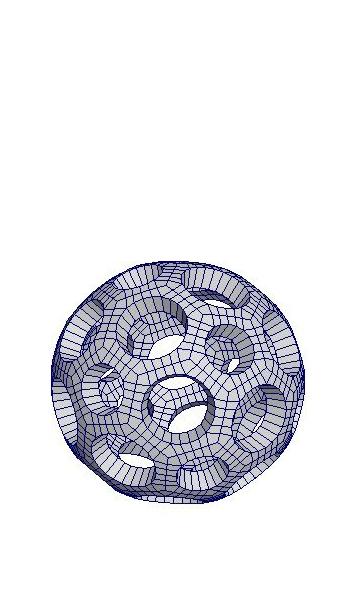
GEOMETRY REFINEMENT
After testing the final design output a refinement of the geometry was needed to optimize the fabrication process as well as dealing with the restraints of the bounding box and waste management.
This diagram below shows the cutting sequence of the first test and the number of cuts

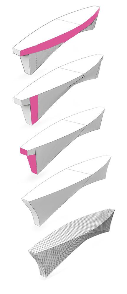
These steps indicate the process followed for geometry refinement.
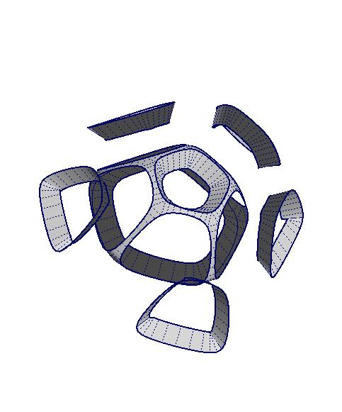
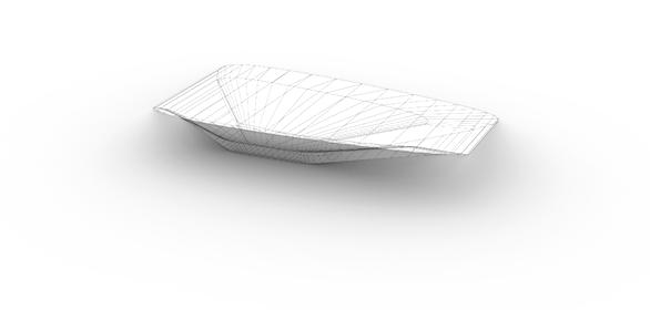
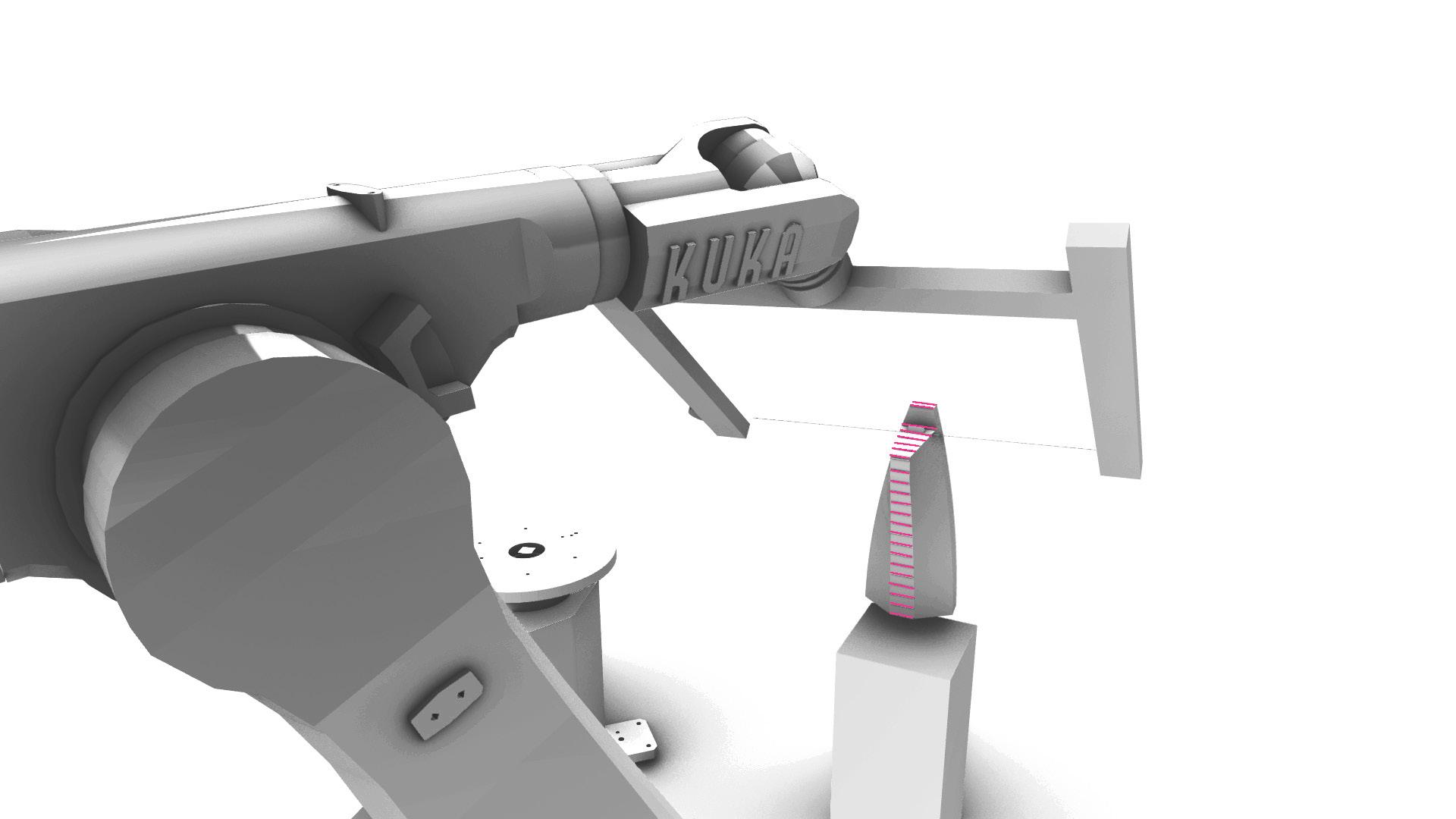
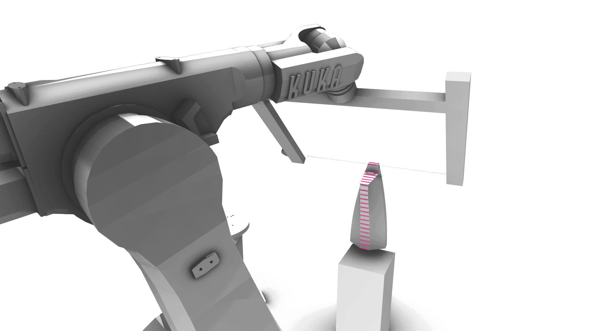
The final fabrication simulation was of the final output of the optimization process.
This diagram below shows the cuts and their location as well as the reduction of cuts needed.


Placement of bounding box
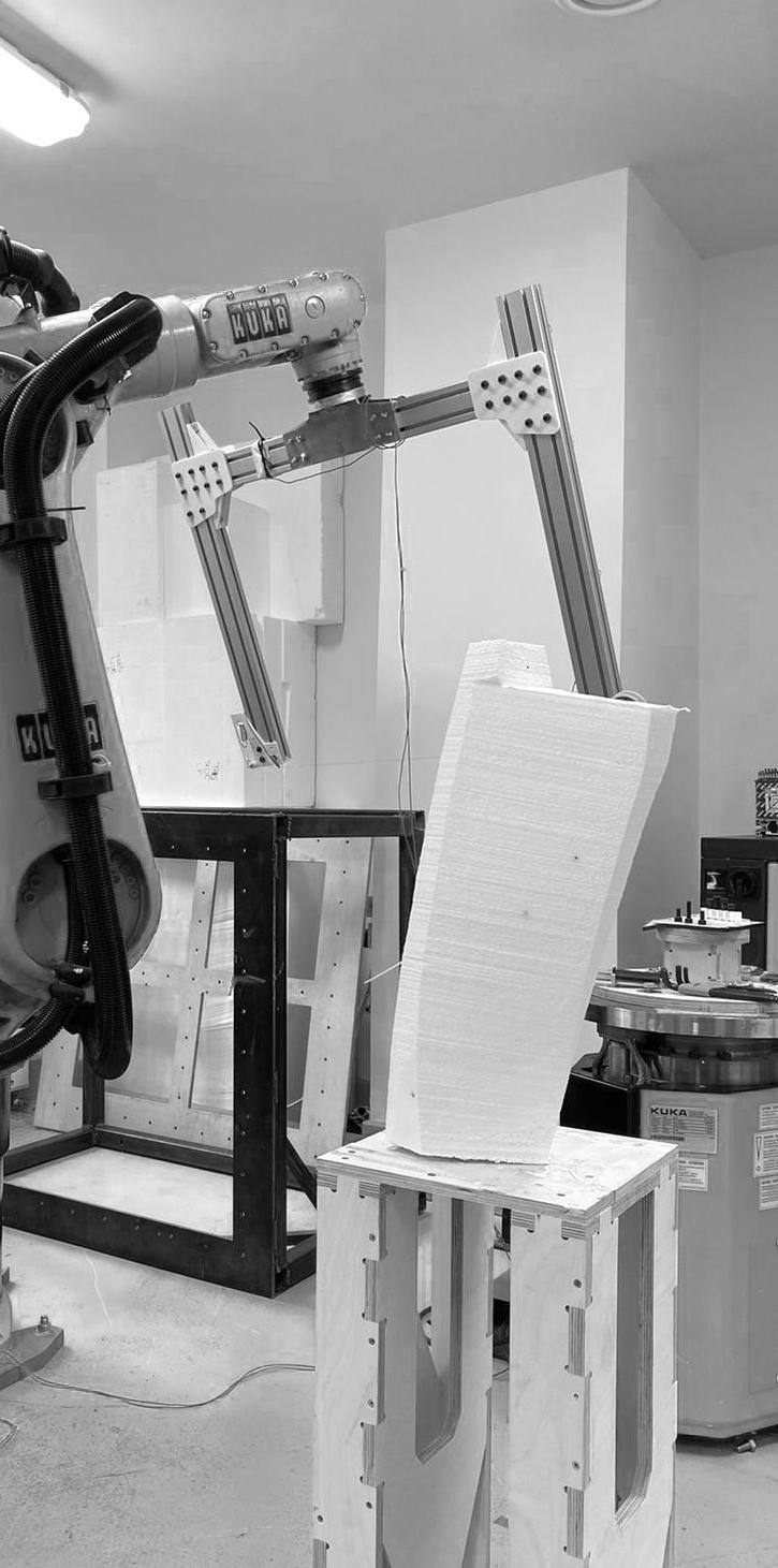
After the refinement of the eight cut model, the resulted model had three cuts and here is the fabrication process invovled in explaining the cuts.
This diagram below shows the cuts and their location as well as the reduction of cuts needed.


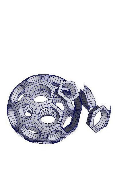
4 5 Composition from the left over parts Bench Composition
These models are made with different compositions of the negatives from the wirecutting process and with the re-use of these components, we can reach a design strategy

Compositions developed from the fabricated mass

Architectural Association School of Architecture