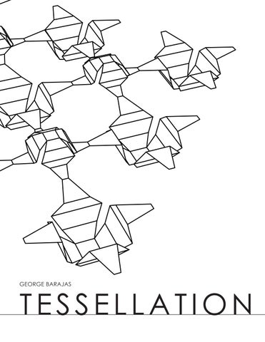
TESSELLATION
GEORGE BARAJAS
2
TABLE OF CONTENTS
×PROCESS
×FINAL
×RENDERINGS
4
×INSPIRATION
6
18
24 3


ABOVE: Initial sketch from week 4 activity.
WEEK 4 ACTIVITY
4
INSPIRATION


LEFT: Top view of sketch model from week 4 activity to show corner connections. BOTTOM: Front perspective to show the object mirrored as if it was standing on glass.


My tessellation was inspired by our week 4 activity. I liked the corner connections and the object being mirrored to give elevation.
5


ABOVE: Initial sketch of variation 1 model. Dashed lines indicate the folds.
VARIATION 1 - SKETCH
PROCESS
6

LEFT: Top view of sketch model variation 1 showing large voids and folds. BOTTOM: Front perspective to show the object height.

The fi rst sketch model was started with a square then cut 4 triangles and mirror them on the edge. The model was folded on the X and Y axis and at 45 ° angles. I did not like the slenderness of the ‘X’ shape or the large voids.
7


ABOVE: Initial sketch of variation 2 model. Dashed lines indicate the folds.
VARIATION 2 - SKETCH
PROCESS
8


LEFT: Top view of sketch model variation 2 showing pleated dome and domes. BOTTOM: Front perspective to show the height and open space under the tessellation.


This sketch had the triangles cut added to the corners and added pleated folds to create a domelike shape. This tessellation is meeting at the corners. I did not like the lack of scale change, the plain corner connection, or simple pattern.
9


ABOVE: Initial sketch of variation 3 model. Dashed lines indicate the folds.
VARIATION 3 - SKETCH
PROCESS
10


LEFT: Top view of sketch model variation 3 showing size difference. BOTTOM: Front perspective to show the height and the distance between objects.


This iteration has 2 different sizes of shape, 1 bigger and 1 smaller, in the fi nal product the larger piece is fl ipping for a more dynamic elevation. Only 3 pleated folds were done for the dome and the shapes are now connected at 45 ˚ corner. The fi nal model for this portion of the process shows the fl ipped variation.
11


ABOVE: Top view of fi nal variation 3 from fi rst portion of the process.


VARIATION 3 - PHYSICAL MODEL
PROCESS
12


TOP: Perspective view showing dynamic shadows. MIDDLE: A more front elevation/ perspective view to see some play in height between the two objects. BOTTOM: An action shot as if someone is walking between the shapes.
13


ABOVE: The unrolled surface view of the 2 components that further enhanced variation 3. Tabs were added for easier connection and adjusted folding lines.
VARIATION 4 - ENHANCED
PROCESS
CUT CUT FOLD FOLD 14
LEFT: Top view of a make 2d to see how the model should look before being built. BOTTOM: A front elevation of the tessellation model to give an idea of height.
Variation 4 was made to enhance variation 3 by making a digital model. Tabs were added to give a solid connection point, the triangle corners were widen to prevent a rectangle look at the corner, and the closet fold became thinner.
15


ABOVE: Top view of fi nal variation 3 from fi rst portion of the process.
VARIATION 4 - ENHANCED
PROCESS


16


TOP: Zoomed in to look at one of the upturned pieces. MIDDLE: An underside view of the lifted component. BOTTOM: Another view of showing height difference and the tab connection corners.
17


ABOVE: The fi nal 2 components in an unrolled surface that improve the fi nal model. The pieces were enlarged, the tabs fl are out, and angles tighten up.
COMPONENTS & MAKE 2DS
FINAL
CUT CUT FOLD FOLD 18
ABOVE: A top perspective view of the updated tessellation.
BOTTOM: A front perspective elevation of the tessellation showing the repetition.
The fi nal model was brought together from previous models. The pieces as a whole were enlarged, the tabs were made longer and fl ared out to grab more, and the corners taper more to the center
19


ABOVE: Top view of fi nal laser cut model.


FINAL 20
MODEL IMAGES


ABOVE: Zoomed in to look to see how the pieces come together with the smaller dome facing up and the larger dome facing down.
21


ABOVE: A view of the shadows that the structure can cast.


FINAL 22
MODEL IMAGES


ABOVE: This is a perspective of what walking through the structure can look like.
23


ABOVE: Zoomed in view of shadows casted from digital tessellation.
RHINO MODEL
RENDERINGS
24


ABOVE: Zoomed out view of tessellation showing the mass grouping.

25


ABOVE: Tessellation pattern shown on exterior of a building as a screen.
APPLIED TO IMAGE
RENDERINGS
26


ABOVE: Interior view of the tessellation as if painted on the wall.
27