In-depth technology for radio engineers
radioworld.com | October 18 2023 | $5.00
Cover Image?
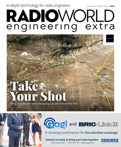
Take Your Shot
Things to consider when designing a studio-transmitter link.
and A winning combination for live election coverage Contact us today to bring your team together www.comrex.com | +1 978-784-1776 | info@comrex.com
BROADCAST RELIABLE