Welcome to the April 5th, 2023 issue of
Radio World Engineering Extra

Stream up to eight programs at once, each with four outputs for a total of 32 streams. Full suite of stream-specific audio processing tools. Optimize performance of audio content.
AAC, MP3 and Opus encoders. Reaching a broad range of end user devices and players.

Metadata agnostic. Lua transformation filters adapt metadata input from any automation system into any required output format.
Cloud-ready for the future, yet compatible with standard CDN and streaming platforms now. Supports HLS, Icecast, RTMP, and RTP streams.
All-inclusive Linux and AoIP appliance. No Windows® drivers, updates or PC needed. Add Streamblade to any audio network via WheatNet-IP, analog, AES3, or AES67 inputs or add Wheatstream to any existing WheatNet-IP or AES67 compatible networks.

wheatstone.com/stream-rw21a


www.radioworld.com
FOLLOW US www.twitter.com/radioworld_news www.facebook.com/RadioWorldMagazine
CONTENT
Managing Director, Content & Editor in Chief Paul J. McLane, paul.mclane@futurenet.com, 845-414-6105
Content Producer & SmartBrief Editor Elle Kehres, elle.kehres@futurenet.com
Technical Advisors Thomas R. McGinley, Doug Irwin Technical Editor, RW Engineering Extra W.C. “Cris” Alexander
Contributors: Susan Ashworth, David Bialik, John Bisset, Edwin Bukont, James Careless, Ken Deutsch, Mark Durenberger, Charles Fitch, Donna Halper, Alan Jurison, Paul Kaminski, John Kean, Larry Langford, Mark Lapidus, Michael LeClair, Frank McCoy, Jim Peck, Mark Persons, Stephen M. Poole, James O’Neal, T. Carter Ross, John Schneider, Dan Slentz, Dennis Sloatman, Randy Stine, Tom Vernon, Jennifer Waits, Steve Walker, Chris Wygal
Production Manager Nicole Schilling
Group Art Director Nicole Cobban
Senior Design Director Lisa McIntosh
Senior Art Editor Will Shum
ADVERTISING SALES
Senior Business Director & Publisher, Radio World John Casey, john.casey@futurenet.com, 845-678-3839
Publisher, Radio World International
Raffaella Calabrese, raffaella.calabrese@futurenet.com, +39-320-891-1938
SUBSCRIBER CUSTOMER SERVICE
To subscribe, change your address, or check on your current account status, go to www.radioworld.com and click on Subscribe, email futureplc@computerfulfillment.com, call 888-266-5828, or write P.O. Box 1051, Lowell, MA 01853.
Licensing/Reprints/Permissions
Radio World is available for licensing. Contact the Licensing team to discuss partnership opportunities. Head of Print Licensing Rachel Shaw licensing@futurenet.com
MANAGEMENT
SVP Wealth, B2B and Events Sarah Rees
Managing Director, B2B Tech & Entertainment Brands Carmel King
Vice President, Sales, B2B Tech Group Adam Goldstein
Head of Production US & UK Mark Constance
Head of Design Rodney Dive
FUTURE US, INC.
Future US LLC, 130 West 42nd Street, 7th Floor, New York, NY 10036
All contents ©Future US, Inc. or published under licence. All rights reserved. No part of this magazine may be used, stored, transmitted or reproduced in any way without the prior written permission of the publisher. Future Publishing Limited (company number 02008885) is registered in England and Wales. Registered office: Quay House, The Ambury, Bath BA1 1UA. All information contained in this publication is for information only and is, as far as we are aware, correct at the time of going to press. Future cannot accept any responsibility for errors or inaccuracies in such information. You are advised to contact manufacturers and retailers directly with regard to the price of products/services referred to in this publication. Apps and websites mentioned in this publication are not under our control. We are not responsible for their contents or any other changes or updates to them. This magazine is fully independent and not affiliated in any way with the companies mentioned herein.
If you submit material to us, you warrant that you own the material and/or have the necessary rights/ permissions to supply the material and you automatically grant Future and its licensees a licence to publish your submission in whole or in part in any/all issues and/or editions of publications, in any format published worldwide and on associated websites, social media channels and associated products. Any material you submit is sent at your own risk and, although every care is taken, neither Future nor its employees, agents, subcontractors or licensees shall be liable for loss or damage. We assume all unsolicited material is for publication unless otherwise stated, and reserve the right to edit, amend, adapt all submissions.
Radio World (ISSN: 0274-8541) is published bi-weekly with additional issues in February, April, June, August, October and December by Future US, Inc., 130 West 42nd Street, 7th Floor, New York, NY 10036. Phone: (978) 667-0352. Periodicals postage rates are paid at New York, NY and additional mailing offices.
POSTMASTER: Send address changes to Radio World, PO Box 1051, Lowell, MA 01853.
Acouple of years ago in these pages, I told the story of the worst lightning damage to a transmitter site that I have ever seen.
In the dead of a Michigan winter, lightning struck the 500-foot tower for our Detroit FM station. It traveled down the tower, followed the transmission line inside to the transmitter, then ran across the transmitter chassis looking for a path to ground. It found several, one of which was through the AC power connection to the transmitter, vaporizing all 14 of the fuse holders mounted on the front of the power supply cabinet of the Continental transmitter.
Cris Alexander CPBE, AMD, DRB Technical EditorAs I told you then, that lightning event showed us a severed ground strap that should have carried the energy from that strike safely into the ground and away from our equipment. It taught me to make checking ground connections, particularly at tower bases and building entry points for transmission lines part of the regular site inspection routine.
In the years since, these inspections have shown up stolen ground conductors and ground bus bars at sites. Thankfully we found the issues before something awful happened in each case.
It’s here!
I mention this again for a couple of reasons.
One is that “lightning season” is upon us in the northern hemisphere. Spring tends to bring thunderstorms in many parts of our nation. We get most of our severe weather toward mid-summer where I live in the Rocky Mountain region. But wherever you call home, the coming of spring is a good reminder to check grounds, ground conductors, grounding blocks and bus bars, TVSS modules and whatever other measures you have in place.
Another reason is that copper theft is again on the rise. Seems like it took a break for the past couple of years, with copper prices dropping into the $3 per pound range.
Now that they’re well over $4 a pound, copper is back on the radar of thieves. Heavy ground blocks, bars and conductors are very attractive targets.
The trouble for us is that there’s no immediate indication that our facility’s grounding has been hit in most cases. So here’s your reminder to add that back in to your visual inspection checklist (if it ever came off).
Another thing I have learned over the years about lightning strikes is that even with the bestgrounded tall metal objects, all that current to ground creates a heck of an H- (or magnetic) field while the current is actually flowing. That H-field can do all kinds of mischief as its lines of flux cut conductors in the area.
Back in the late 1980s, I took a direct lightning hit to the amateur radio tower in my backyard. The simultaneous blast of thunder was LOUD and very sharp, and just about stopped my heart!
In addition to the screaming smoke alarms and ruined radios, that strike turned our television screen purple. Every image on the screen was purple. I knew exactly what the cause was, and thankfully I had a degaussing loop that I was able to run over the screen and get the colors back right, but it was a good object lesson on the intensity of that H-field.
On many occasions since, we’ve taken hits on various towers at studios and transmitter sites, towers that were well grounded and where the lightning current was shunted safely off to ground without going through any of our equipment — and yet we still took damage. The harm was entirely to components and devices that were connected to runs of audio, AES or network cables.
In an earlier analog age, we would see input and output op-amps get blasted. In more recent digital days we see switch ports and NICs get damaged. Why? It’s because those very intense lines of magnetic flux cut the conductors in audio and network cables and induce a damaging current into the conductors within. That current has to go somewhere, and that somewhere is equipment inputs, outputs and network ports.

There are things that can be done to mitigate this kind of damage.
You can place ferrite cores on network and audio cables. You can use shielded cables; you can run cables in an EMT conduit.
Above Grounding blocks like this one are prime targets for copper thieves if not protected, and a block’s absence may not be detected until it’s too late.
Snap-on ferrites of the type often seen on wall-wart power supplies and other computer cables to maintain Part 15 compliance are relatively cheap and readily available from your favorite electronic component supplier.
There are network surge suppressors available, some of which are very good, but it’s impractical to put one on every network cable.
Perhaps the best thing to do is evaluate your facility for the most vulnerable cable runs and protect those with ferrites and conduit. Otherwise, keep spare parts on hand, including shelf spares of your core network switches, all configured up and ready to swap out in a hurry if the worst happens.
The sad truth is that the only way to “lightning proof” a piece of equipment is to put it under the bed where you’re sleeping. That way, the lightning has to go through you to get to it. It might still get through, but if it does, it won’t matter to you!
In this issue of RWEE, Steve Walker of Wheatstone is going to give us some great pointers on protecting our studio and transmitter facilities from lightning damage. His tips provide a benchmark for evaluating our facilities to be sure we’ve done things right, hopefully before we find out the hard way that we haven’t.
Also, Tom Vernon is going to give us a look at the NAB’s PILOT Radio Test Bed that you — yes you! — can use to evaluate the performance of various devices under differing conditions.
So check those grounds and settle in for a good read. We hope you’ll learn something.
 Writer
 Corp.
Corp.
Hardly a week goes by that the Wheatstone Tech Support department doesn’t get at least one call from a customer who is having equipment issues due to a lightning strike or power surge.
While it may not be possible to eliminate damage caused by electrical events such as these completely, there are some best practices you can implement in your new studio build (or even in your existing facility) that can minimize the likelihood of consoles or other audio equipment being destroyed by the electromagnetic pulse that results from these events.
Lightning and power surges create short but powerful over-voltage conditions in your electrical systems that can damage sensitive equipment. Replacing or repairing
the equipment can be expensive but may seem minimal compared to the loss of revenue if you are taken off the air.
Here are a few things you can do to protect your gear and keep your stations on the air.
An uninterruptible power supply can go a long way toward protecting your broadcast gear from power surges. It has the added benefit of keeping you up and running during short-duration power loss events as well.
You can protect each studio and your TOC area by installing small UPS units to power each cluster of critical pieces of equipment, but having units scattered around your plant means you need to have a strategy for ensuring that the batteries in those units are replaced regularly,

before they start to go bad. Make sure any UPS units you use power the load off the batteries, isolating your gear from the AC mains.
A better, albeit more expensive, option would be a large UPS system that can power your entire TOC and studio core. This is easiest to implement when you are planning a build and might be worth pitching to the decisionmakers as a necessary, integral part of your new plant.
UPS systems alone are only part of the solution. A good grounding scheme can go a long way to protecting your expensive studio gear from the destructive force that is packed in every lightning storm that comes your way.
Wheatstone’s Jeff Keith says, “Grounding in a broadcast facility is more or less a science. But there are some pretty good ground rules (pun intended).” Here are a few of his suggestions:
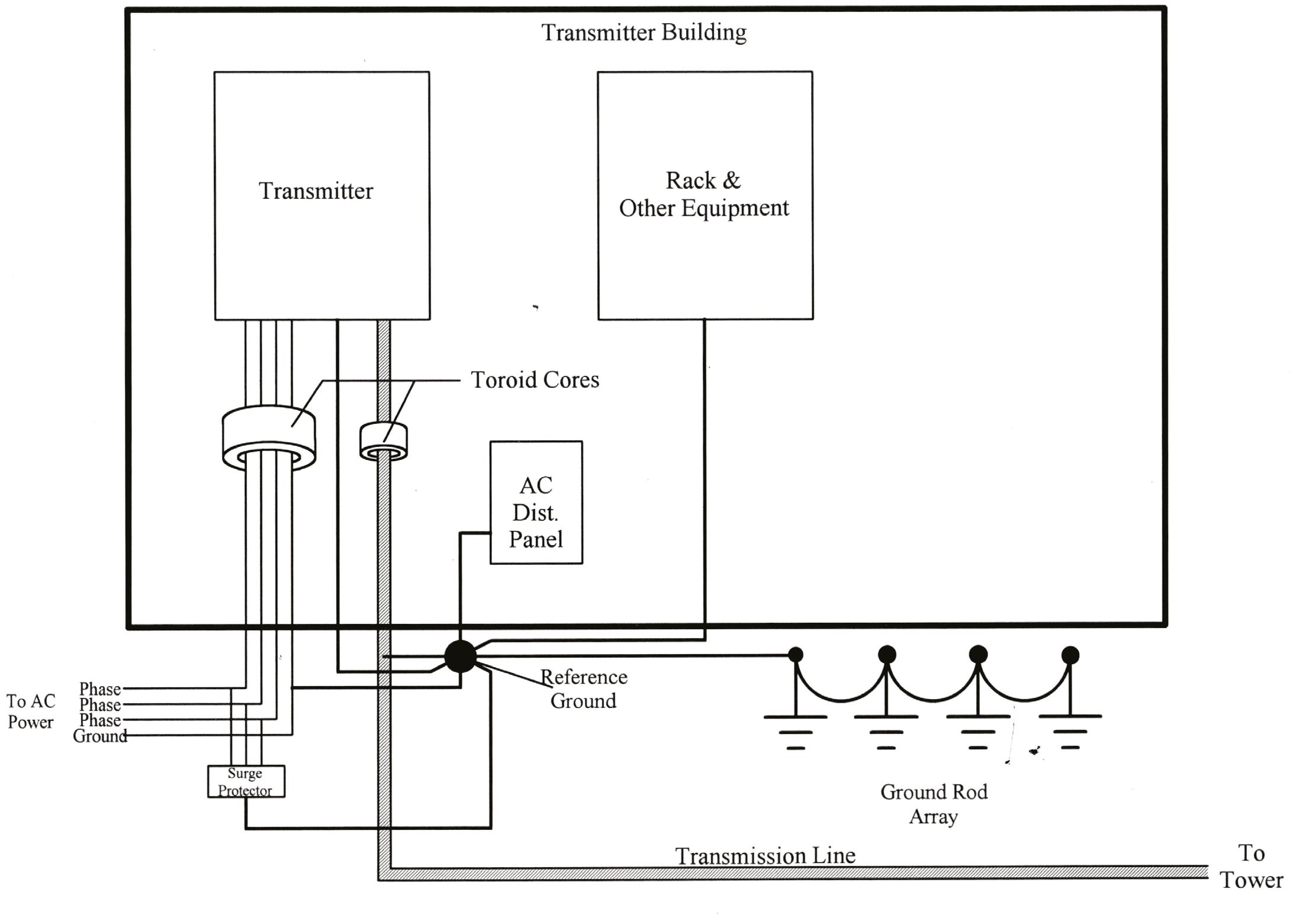
Use a single-point ground, also called a “star” ground system because everything comes back, as much as possible, to a single earth-ground point. See the image above.
“The worst possible condition is for surges to have more than one destination because that usually means there’s some piece of broadcast gear ‘in the middle,’” says Jeff.
Above A single-point “star” grounding scheme provides the best protection in most cases.
“Temporary (surge-related) voltage differences between AC and audio ground are the cause of most of the failures that we see here at Wheatstone. A thousandamp surge across an ohm of ground causes a kilovolt voltage drop.”
Additionally, you will want to use a large conductor for grounds. It might not be easy pulling a 2/0 or 3/0 copper conductor through your house cabling conduits, but the
“
The worst possible condition is for surges to have more than one destination because that usually means there’s some piece of broadcast gear ‘in the middle.’
benefits of a properly designed ground system will pay off big dividends the first time a lightning strike finds that the easiest way through your system is straight to ground. (At transmitter sites you will probably want to use ground straps of at least 2 to 4 inches in width, due to the high RF fields in play.)
“Today we have shielded network cables, too, so there’s another ‘wire’ to consider. And even though network interfaces are transformer-coupled, those transformers are little tiny guys with not much of a ‘gap’ for a 10 to 20 kV wallop. I’ve seen cases where an incoming surge jumped right across the transformer and found its way into the Ethernet switch’s silicon guts and yes, the magic smoke got let out.”
Don’t neglect proper grounding and bonding at the studio. Just because you may not have a 1,500-foot tower in your backyard doesn’t mean you are immune from lightning damage. Do your research and spend the time and money needed to implement a good grounding system at your studio — whether it’s a new build or an existing plant — as well as your transmitter site locations to protect your investment and revenue streams.
When building a facility from the ground up, you have a one-time opportunity to create the best ground system you can.
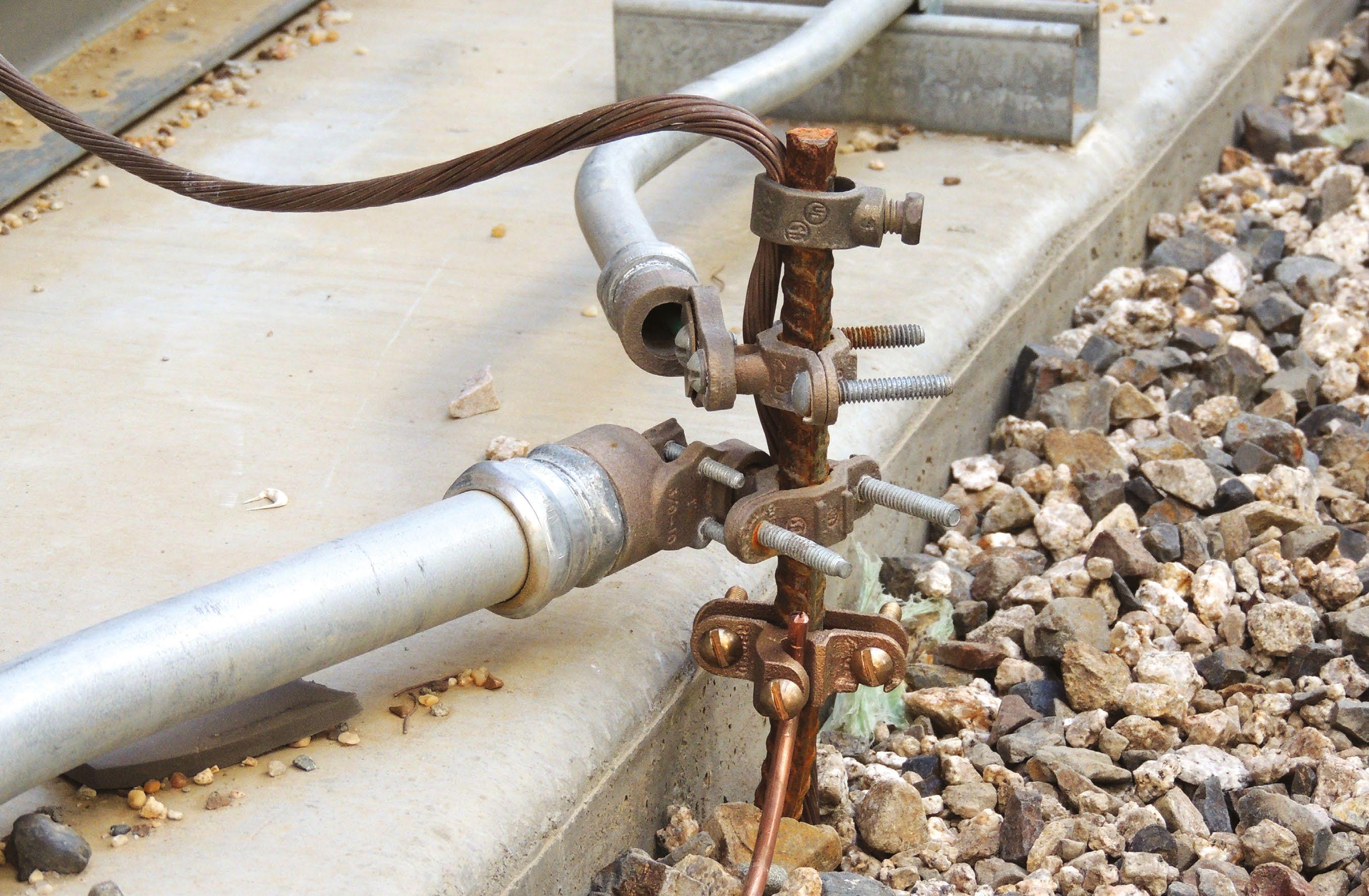
We asked Jeremy Hewitt, senior systems engineer for Inrush Broadcast Services, for his thoughts on facility grounding. He recommends the Ufer ground for new facilities.
“A Ufer ground typically consists of steel reinforcing rod (rebar) directly embedded in concrete. It must be at least 20 feet long, but it is not required to be continuous. If it is not continuous it is permissible for it to be joined via tie wires, welding or exothermic welding. An alternative means of constructing a Ufer ground would be to embed 4 AWG bare copper wire in the concrete.”
The photo on page 6 shows a Ufer ground at a broadcast facility. The Ufer ground system is named after Herbert Ufer, a former U.S. Army consultant. He was tasked with creating an effective and relatively inexpensive grounding means for bomb storage vaults in Arizona.
Due to the dryness of the soil, a ground rod might have to be 100 feet long in order to meet the low resistance requirements, which was not cost-effective or practical.
“In order for a Ufer ground to be effective,” says Jeremy Hewitt, “the concrete must remain in direct contact with
the ground. This means that vapor barriers or thermal insulation must not be installed beneath the slab or foundation. Typically, a Ufer ground produces a resistance to ground of 2 to 5 ohms.”
Of course, the Ufer grounding method is only practical when established as part of a new installation. In lieu of a Ufer ground, multiple ground rods can be used to ensure that a low-resistance path to ground is maintained. Ground rods should be driven into the soil at least 8 feet unless impossible due to encountering rock.
A ground ring in which at least 20 feet of bare copper wire (2 AWG or larger) surrounds the structure and is in direct contact with the earth is another option to ensure a low-resistance path to ground.
Regardless of the type of grounding electrode, the resistance between the electrode and the earth should not be more than 5 ohms. If multiple ground rods are used to achieve this, they should be spaced by half the length of the longest ground rod, for maximum effectiveness. If multiple grounding electrodes are used to lower the resistance, they should be bonded together. In addition, there should be a common connection where all electrical systems are bonded together to ensure that no potential can be created between the systems.
Without a suitable low-resistance facility ground, it is likely that a lightning transient will create a potential high enough to render any built-in transient protection ineffective.
Ideally, an effective facility grounding system would be used in conjunction with an overall surge protective device such that a low-resistance discharge path is created for the surge protective device.
Grounding for your studio or transmitter facilities should never be an afterthought. You have hundreds of thousands of dollars’ worth of high-tech audio, video and RF equipment that depends on being well-grounded for its protection. Lightning strikes and electrical power surges are facts of the engineering life, and as the engineer designing the facility, it’s your job to make sure the potentially damaging current has a better choice for where to travel when it comes to visit than directly into your expensive gear.
“Lightning and power surges create short but powerful over-voltage conditions in your electrical systems that can damage sensitive equipment.


Aseldom-discussed aspect of standards development and equipment testing for AM and FM radio is who does the testing and what kind of gear they use.
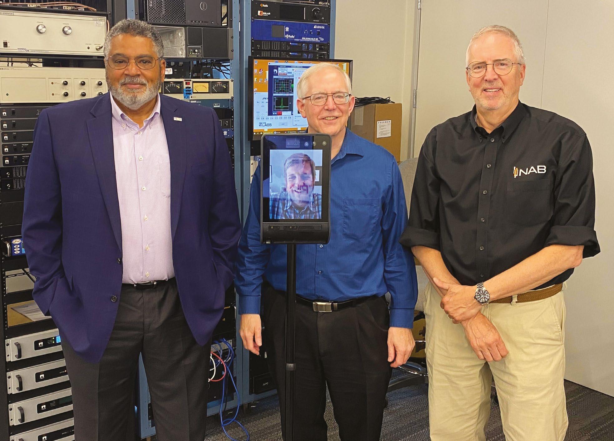
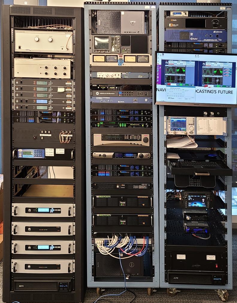
The National Association of Broadcasters today is in a position to do this type of work as part of its PILOT technology initiative. It has a custombuilt radio “test bed” to make those evaluations and gather data. The test bed, which now resides at NAB headquarters in Washington, occupies three racks and is available as a resource for industry projects.
David Layer, vice president, advanced engineering at the NAB, said the test bed has evolved over time to keep up with industry demands.
“It was originally created for the NAB with AM-only capability in 2014. Design and construction were done by Cavell, Mertz & Associates, with Dan Ryson (now with
CBS) and Cavell Mertz senior engineer Mike Rhodes as the principal engineers.”
At that time, the main impetus was all-digital AM HD Radio co-channel interference testing. Layer said the FCC’s technical record on all-digital AM was sparse, so it was up to the industry to supply the necessary data to the commission and push for authorization.
“Under NAB’s leadership, all-digital AM was field-tested at nine stations in the United States, where the emphasis was on coverage. Subsequently, it was lab-tested using the PILOT radio test bed, where the emphasis was on cochannel interference. These efforts contributed greatly to the FCC authorizing digital AM in 2020.
“After the AM work was completed,” Layer continued, “NAB partnered with Cavell Mertz, Nautel and Xperi for HD Radio FM-band MP11 mode testing in 2017. For that,
(2021)
RF CHAN. SIMULATOR
AWGN RF NOISE MONITOR
AUDIO BLADES
AM EXCITERS GEN 3 EXPORTERS
AUDIO BLADES
GEN 3 IMPORTER
RF ATTENUATOR (x8)
(RED INDICATES NEW EQUIPMENT IN 2021 UPGRADE)
FM EXCITERS / TRANSMITTERS
(2021)
SPECTRUM ANALYZER
KEYBOARD
RECEIVERS
2 HD MULTICAST + IMPORTER/EXPORTER


FM capability and a third rack were added to the test bed. FM transmitters and receivers were installed. Nautel built special test equipment for MP11 transmission. The result of this research was Xperi’s rollout of MP11 software, as well as Hubbard Broadcasting and others moving forward with MP11 adoption at their facilities.”
In 2021 the test bed moved from the Cavell Mertz offices in northern Virginia to the new NAB headquarters in southeast Washington. It was also time for another upgrade.
“The original audio distribution system was based on conventional patch panels and had become obsolete by this time. It was replaced with audio blades from Wheatstone,” said Layer. Two test computers, an RF channel simulator and two fourth-generation Nautel HD Multicast+ units were added, as well.
Last year the test bed was further upgraded to add text and image metadata transmission and reception capabilities. RCS contributed a license for their Zetta playout system, while Xperi contributed a license for its RAPID cloud-based metadata management system.
While the test bed may appear a bit intimidating in photos, the concept is fairly simple and more easily understood with flow diagrams.
The transmitter rack RF path contains three Nautel FM transmitters with associated RF attenuators and patch


More Info


For information or to discuss project ideas, send an email to dlayer@nab. org.

bays, as well as three Nautel AM exciters, also connected to the patch bay. There is also an HP 11759C RF channel simulator which is currently being integrated into the test bed.
Transmitters and exciters can be configured so that one is generating the desired signal, while the other two can create undesired signals, to serve as co- or adjacentchannel interference. A NoiseCom NC8107A Noise Generator is also available as an RF noise source.
A Mini Circuits ZFSC-6-1 combiner connects to all the sources, and the output goes to a digitally controllable variable attenuator.
“
Transmitters and exciters can be configured so that one is generating the desired signal, while the other two can create undesired signals.
Use case example –adjacent-channel testing:
RF spectrum plot showing three FM-band HD Radio signals
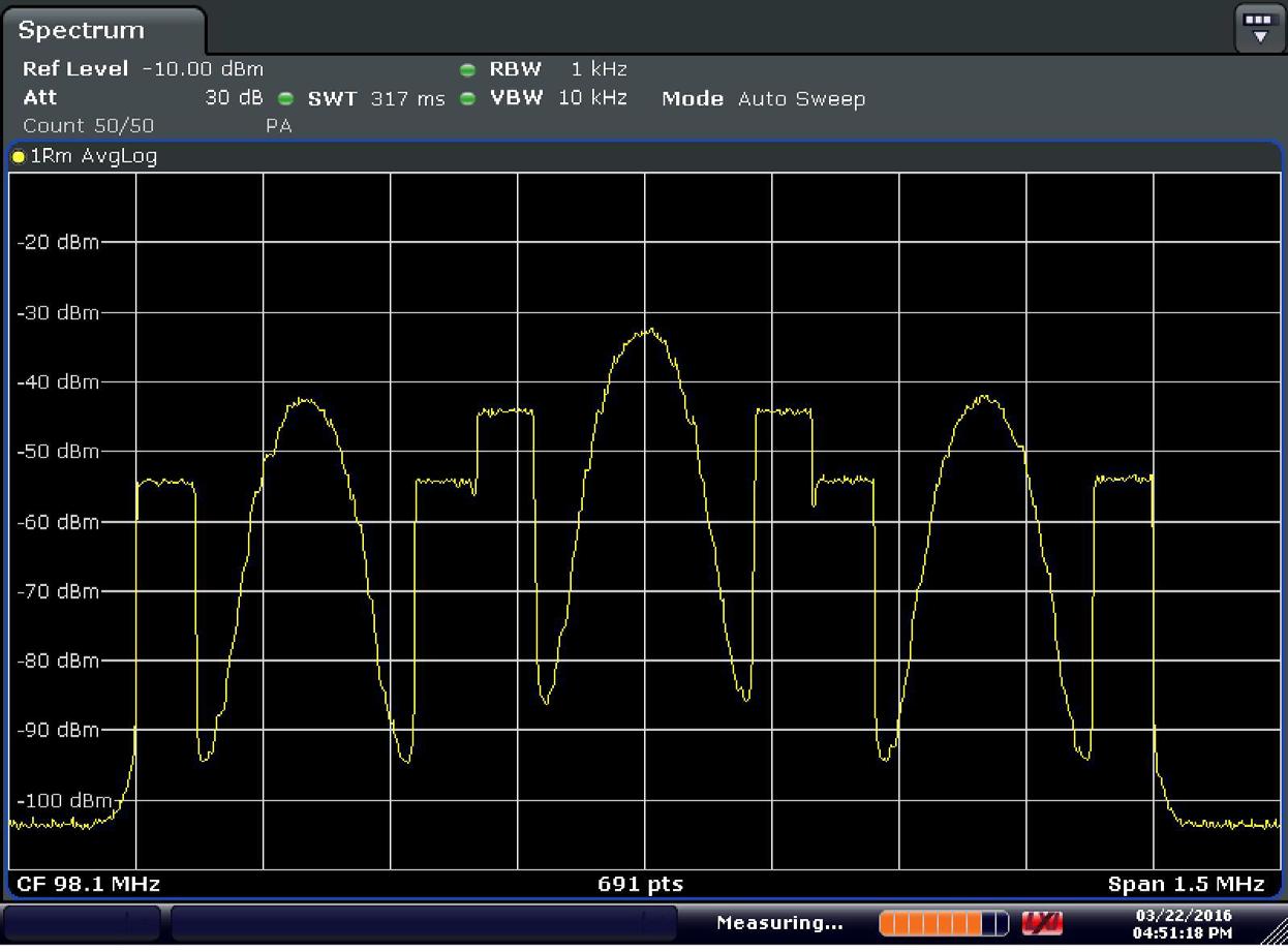
The RF path in the receiver rack begins with a Mini Circuits ZFSC-16-12+ which takes the transmitter rack output and routes it to a number of receivers and measurement devices. This includes up to eight receivers, a spectrum analyzer, Audemat AM/FM mod monitor, Belar FM modulation monitor, Inovonics 638 FM/HD/RCS receiver, Deva Band Scanner, and Audio Precision APx515 audio analyzer.
The audio rack contains analog and digital audio blades, which can route the outputs of all the receivers, RF monitors, audio processors and APx515 analyzer to the inputs of headphones and speakers, and other audio monitors.
Audio processors include a Wheatstone FM, Omnia One AM and Orban 9400 AM. Importers include a Nautel Importer Plus and a pair of HD Multicast+ importer/exporters. Audio monitoring is done via a Tektronix 760 stereo monitor and a McCurdy audio test set.
In addition to the audio and RF paths, there’s a fairly robust test LAN and WheatNet LAN. Network switches are a Netgear GS-108 for the test LAN, while the WheatNet LAN uses a Cisco switch 3650. Internet access/firewall protection is provided by a Netgear FVS-114.
Layer adds, “NAB’s goal is for the PILOT radio test bed to serve as a resource for the radio industry, and we encourage all stakeholders to reach out with project and application ideas that will allow this test bed to have an impact on the testing and development of broadcast radio technology for many years to come.”

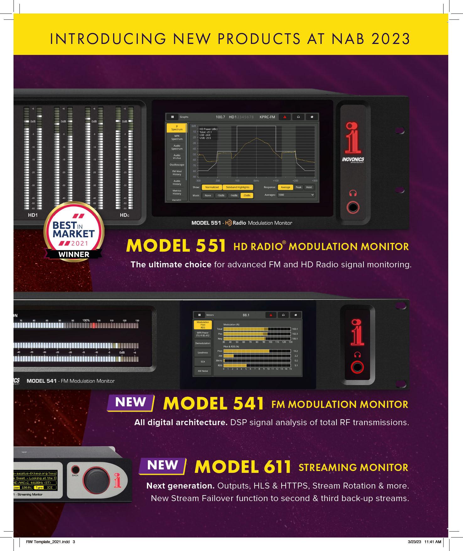
A fourth-generation modulation monitor for FM stations is the latest product from Inovonics.
“The new 541 incorporates all the necessary features for station setup, regulatory compliance and remote monitoring,” the company said. “The 5-inch colorful LCD Touch Screen displays all the essential modulation data in a graphic format on the front panel, or can be viewed remotely on any Web-enabled device.”
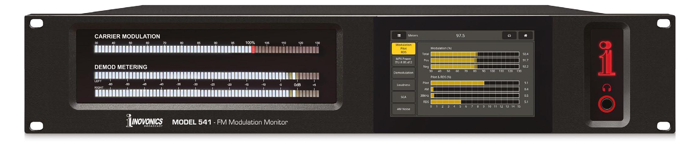
The 541 delivers information about the transmitted signal in terms of the RF carrier and all subcarriers, the audio component defining the technical quality that the listener hears, and decoding of RDS data and SCA audio.
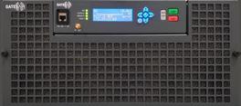
Tieline will unveil two codecs at the NAB Show.
The MPX I and MPX II offer composite FM multiplex solutions for real-time network distribution of FM-MPX or MicroMPX (µMPX) signals to transmitter sites, the company said.
It noted that sending “transmission-ready” FM composite signals from the studio allows stations to keep audio processing and RDS gear at the studio, which it says can save money and operating costs. “Composite MPX over IP signals can be easily replicated and distributed using multicast and multi-unicast technologies and take advantage of rock solid redundancy features like redundant streaming, RIST, FEC and automated SD card file failover.”
“The MPX I is ideal for transmitting a composite STL signal from a single station with return monitoring, whereas the Tieline MPX II can transport two discrete composite FM-MPX signals from the studio to transmitters with return monitoring.”
“The digital architecture of the 541 combines detailed DSP signal analysis with a menu-driven touchscreen display, plus Web serverbased total access for remote operation, including measurements, graphical data and direct Web-browser audio monitoring of the offair program.”

Inovonics quotes President/CEO Ben Barber saying that the product reflects its experience in developing the 551 and 552 models. “With the dynamic web interface that can be remotely accessed from any smart phone, tablet or PC, and its SNMP capabilities, the 541 takes innovation to a new level.”
Info: www.inovonicsbroadcast.com/product/family/monitors
The products will ship later this year. Both support analog MPX on BNC, MPX over AES192, and multipoint signal distribution, to deliver composite encoder and decoder solutions for various applications.
“The MPX I and MPX II support sending the full uncompressed FM signal, or high-quality compressed µMPX at much lower bit rates. An optional satellite tuner card with MPEG-TS and MPE support can receive DVB-S or DVB-S2 signals.”
The announcement was made by VP Sales APAC & EMEA Charlie Gawley. “By supporting both analog and digital composite MPX signals, broadcasters can transition from analog to digital exciters over time and maximize the value of their MPX investment,” he said.
Info: http://tieline.com