


HEAT PUMP & HEAT RECOVERY

VRF CATALOGUE
Variable Refrigerant Flow System
(1-way Flow type)
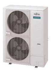
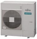
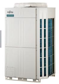
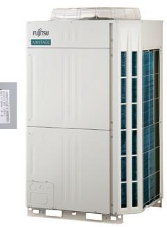
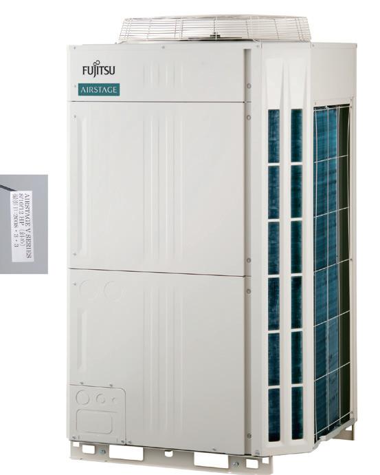
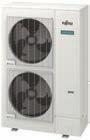
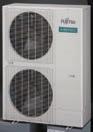
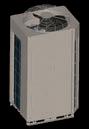
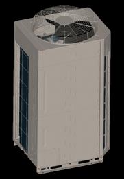
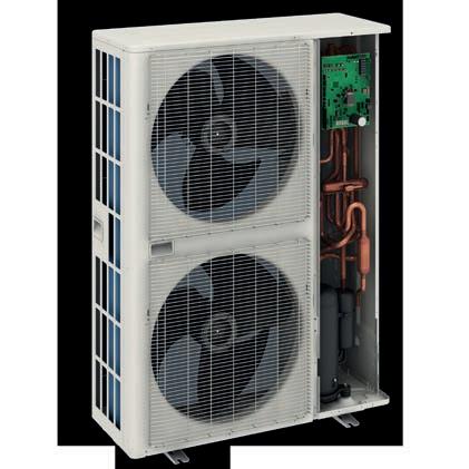
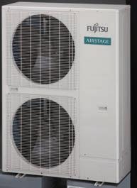
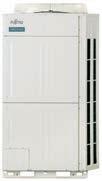
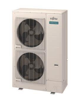
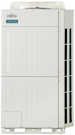
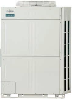
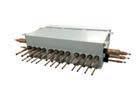
AIRSTAGE J-IVL 14 / 16 HP model
HEAT PUMP & HEAT RECOVERY
(1-way Flow type)
AIRSTAGE J-IVL 14 / 16 HP model
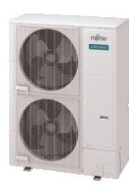
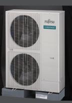
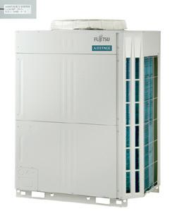
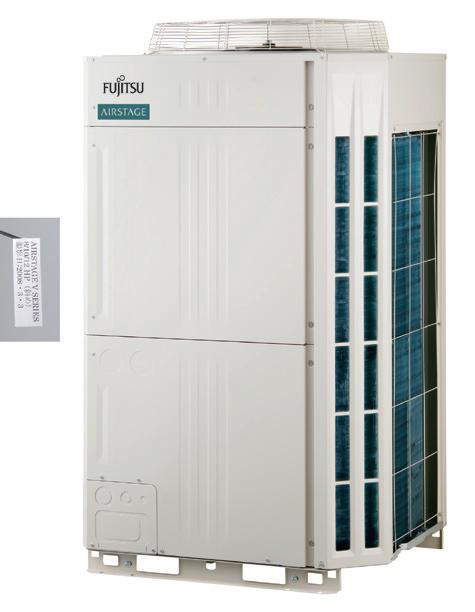
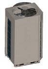
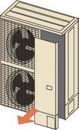
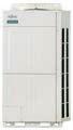
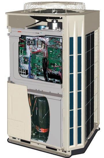
AIRSTAGE VR-IV 8 HP model
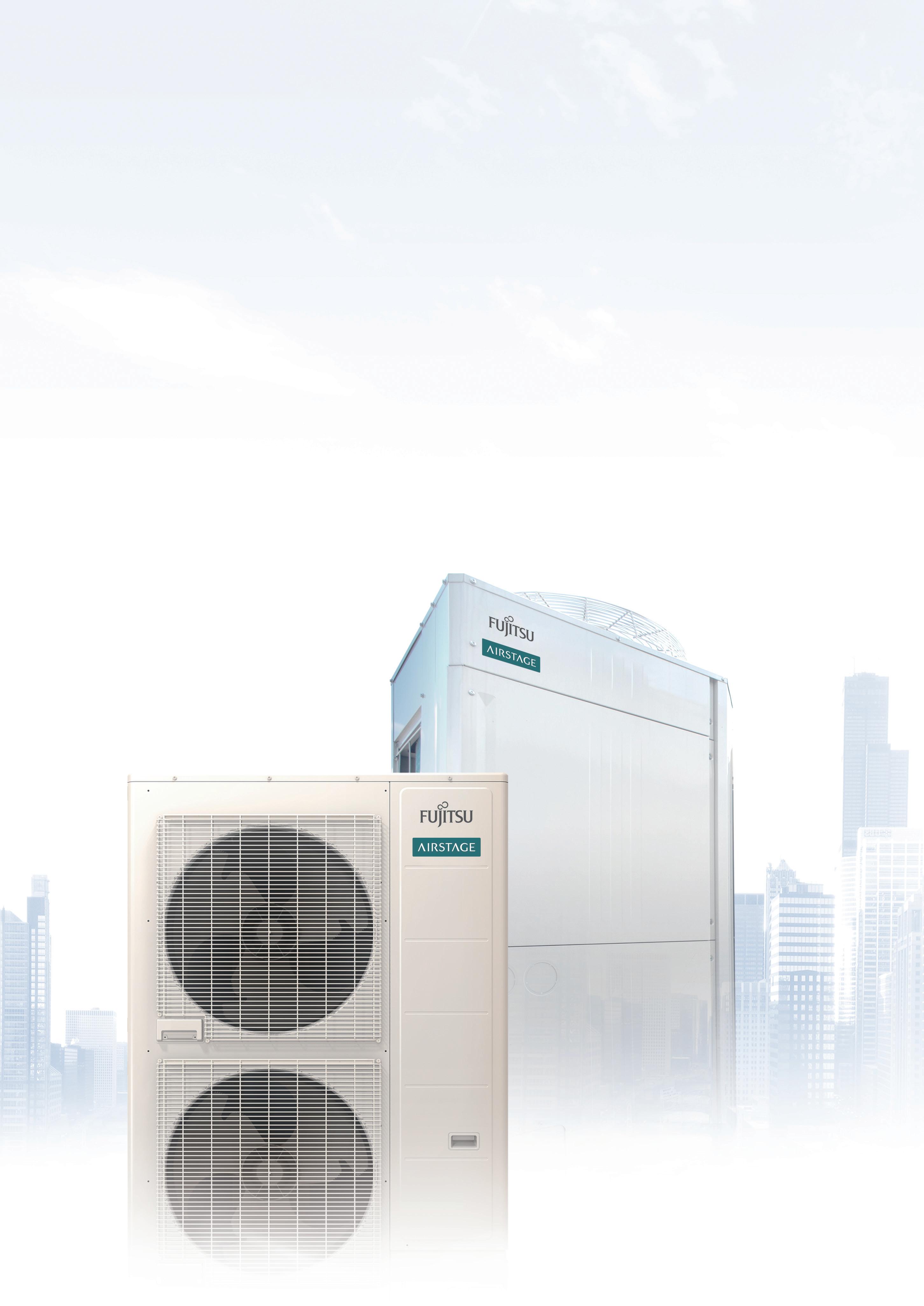
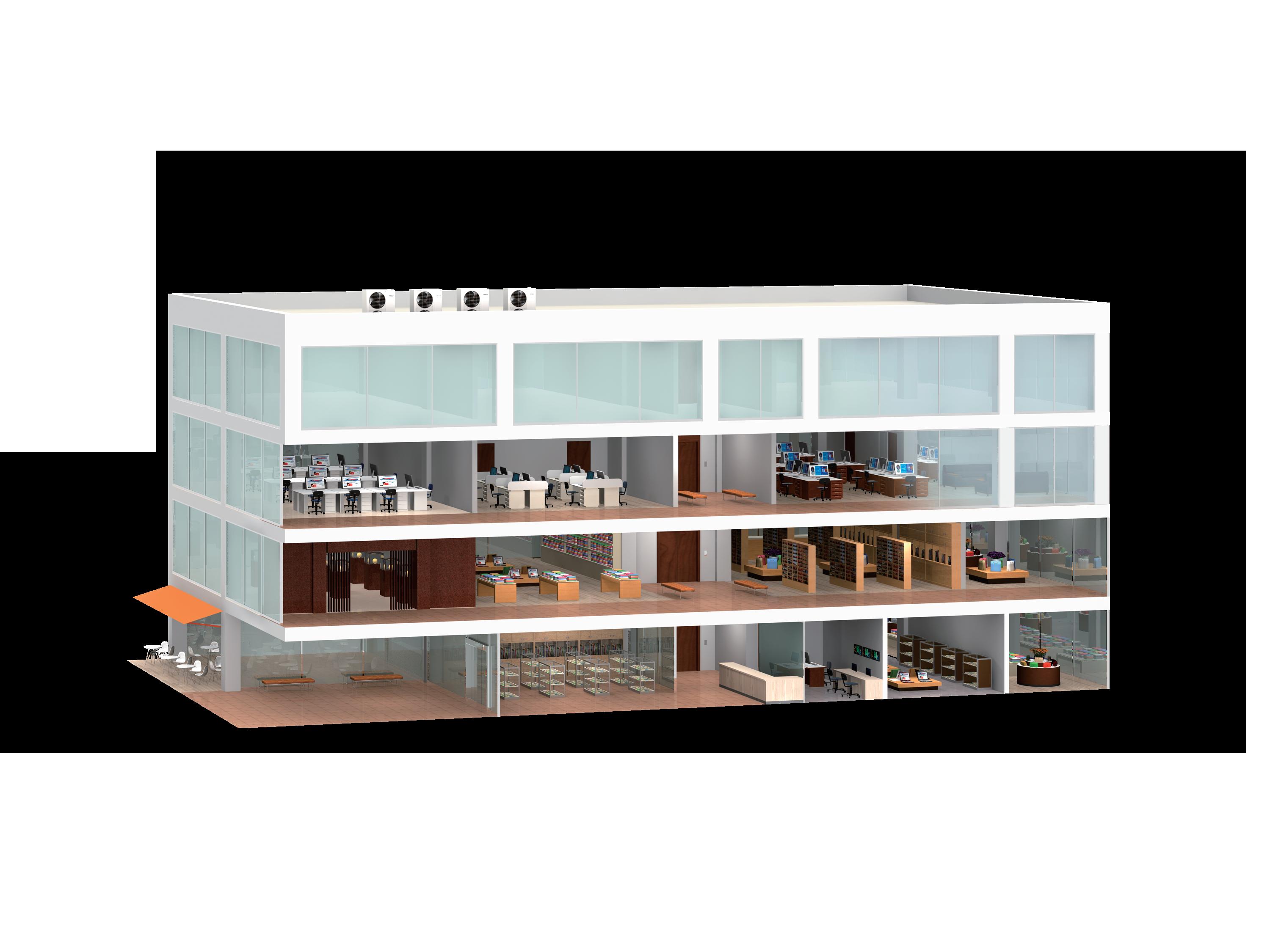
The AIRSTAGE ™ Series provides high energy savings, comfort, and reliability to the end user.
Design, installation, and servicing are highly flexible and simple. We offer an abundant VRF System lineup to match regional and local customer needs with a range of combinations from low to high capacity.
Heat Pump type
8 HP - 16 HP 5 Models / 3 phase
Heat Pump type
4 HP - 6 HP 3 Models / Single phase
Heat Pump type
4 HP - 6 HP 3 Models / Single phase
Heat Recovery Modular type for simultaneous heating and cooling operation
8HP - 48HP 33 models
• Space saving combinations: 8 HP to 48HP / 21 models
• Energy efficiency combinations: 16HP to 42HP / 12 models

Heat Pump Modular type
8HP - 48HP 33 models
• Space saving combinations: 8 HP to 48HP / 21 models
• Energy efficiency combinations: 16HP to 42HP / 12 models
004 FLEXIBLE SOLUTIONS
006 LIGHT COMMERCIAL SOLUTIONS
010 COMMERCIAL SOLUTIONS
014 AIRSTAGE CORE TECHNOLOGY
016 HIGH ENERGY EFFICIENCY
018 MAXIMISED COMFORT
020 CONSISTENT RELIABILITY
022 DESIGN FLEXIBILITY
024 EASY INSTALLATION
026 EASY SERVICE & MAINTENANCE
028 AIRSTAGE SERIES
030 AIRSTAGE ™ LINEUP
032 HEAT PUMP TYPE AIRSTAGE ™ J-IVS 036 HEAT PUMP TYPE AIRSTAGE ™ J-IV
040 HEAT PUMP TYPE AIRSTAGE J-IVL 046 HEAT PUMP
062 AIRSTAGE™ INDOOR UNITS
064 INDOOR UNITS LINEUP
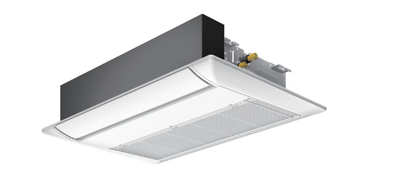
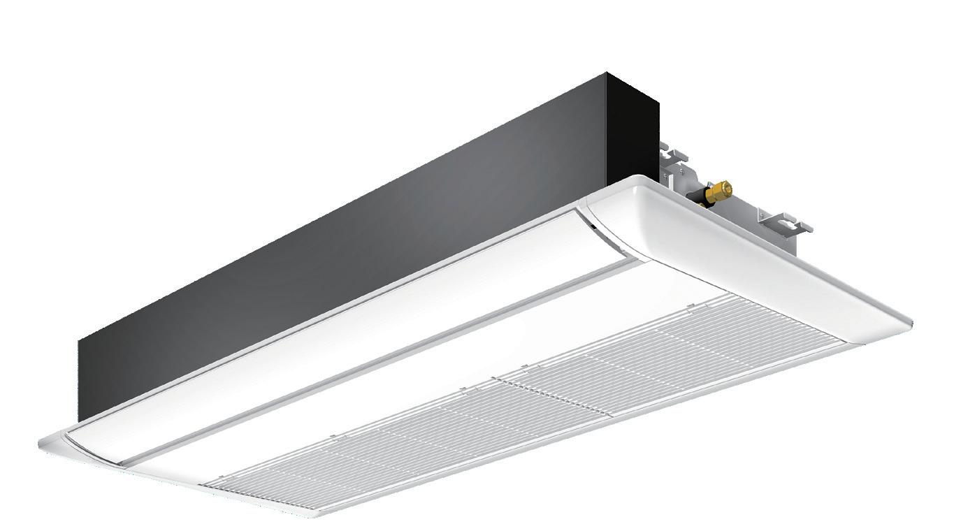
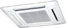
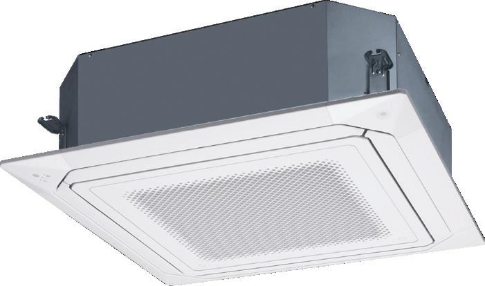
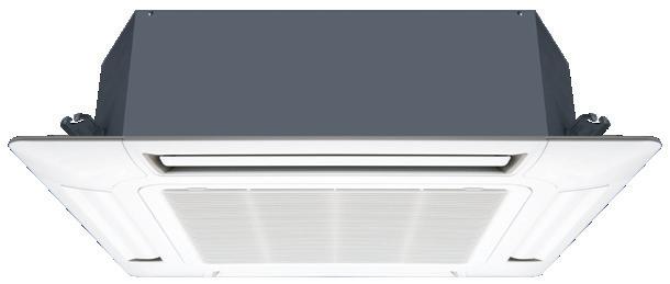
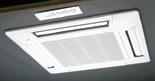
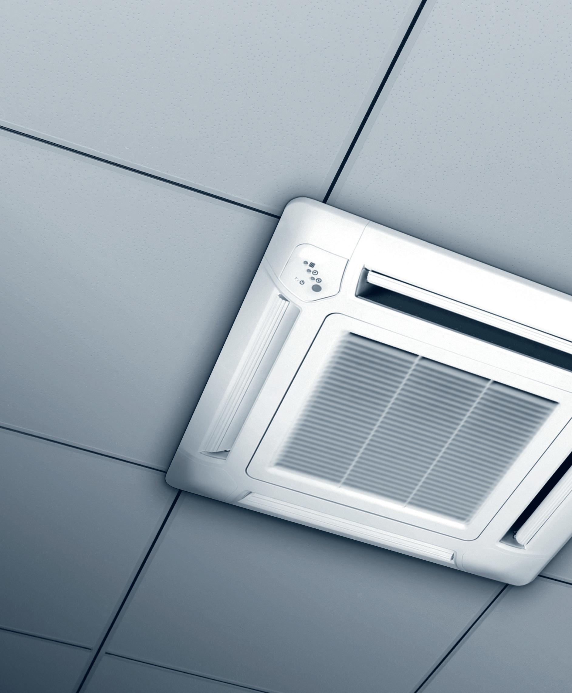
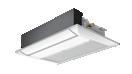
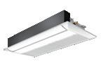
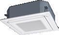
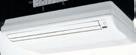
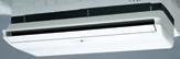
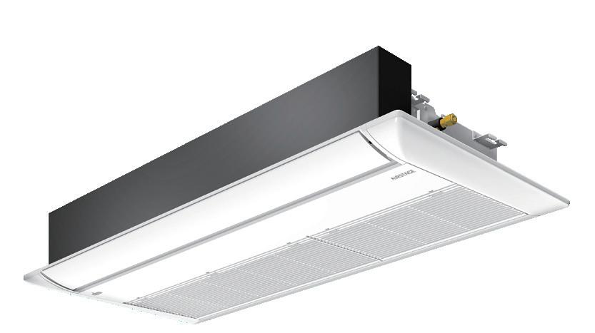
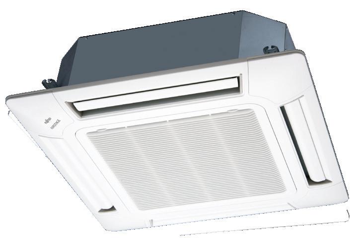
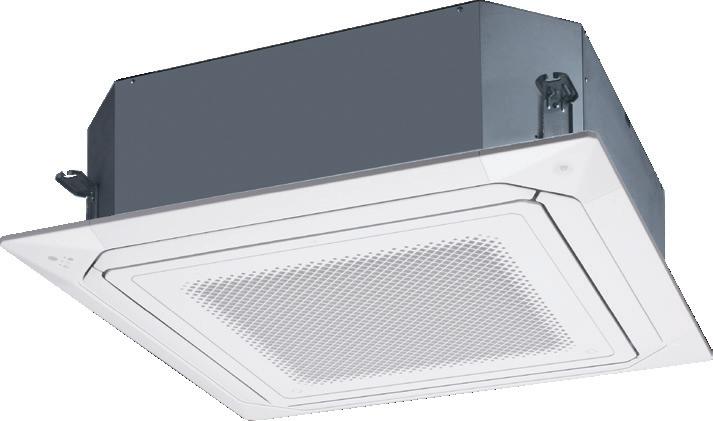
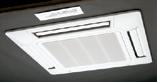
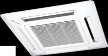
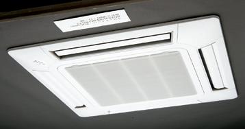
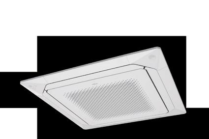
066 Cassette (1-way Flow type)
068 4-way Flow Compact Cassette
070 4-way Flow Cassette
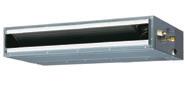
072 Circular Flow Cassette 076 Mini Duct 078 Slim Duct / Slim Concealed Floor 080 Medium Static Pressure Duct 082 High Static Pressure Duct 084 Floor (compact) 086 Floor / Ceiling
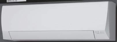
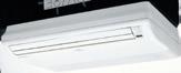
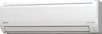
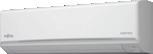
Ceiling 090 Wall Mounted (EEV Internal / external)
096 Outdoor-air Processing Unit
™ CONTROL SYSTEMS
TABLE OF CONTROLLERS
INDIVIDUAL CONTROLLER
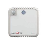
anywAiR iO SMART BUILDING SOLUTIONS
CONTROLLER
/ ADAPTOR
™ OPTION
Power Supply Unit
Auto Louvre Grille Kit
PARTS LIST
INPUTS AND OUTPUTS
AND REFRIGERATION ACCESSORIES
HISTORY
WIDE LOCATIONS
REFERENCES

DEVELOPMENT AND PRODUCTION BASES
QUALITY DEVELOPMENT AND
Fujitsu General has been developing and manufacturing high quality and energy efficient products for more than 35 years. Using the latest Japanese technology and state of the art expertise, our products have been designed in accordance with our aim of creating the most comfortable environment possible, regardless of the project type or design.

High Energy E ciency
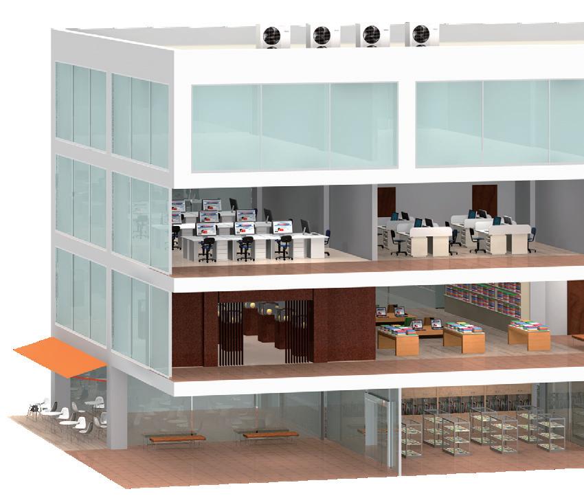
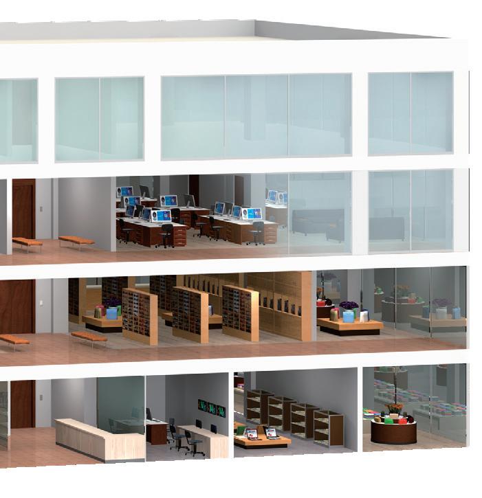
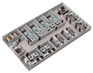
Fujitsu General offers a diverse range of air conditioning systems focused on residential and small sized buildings.
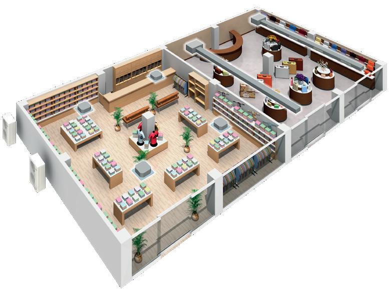
Fujitsu General provides single and modular type VRF systems with efficient operation, comfort, design flexibility, easy installation and consistent reliability.
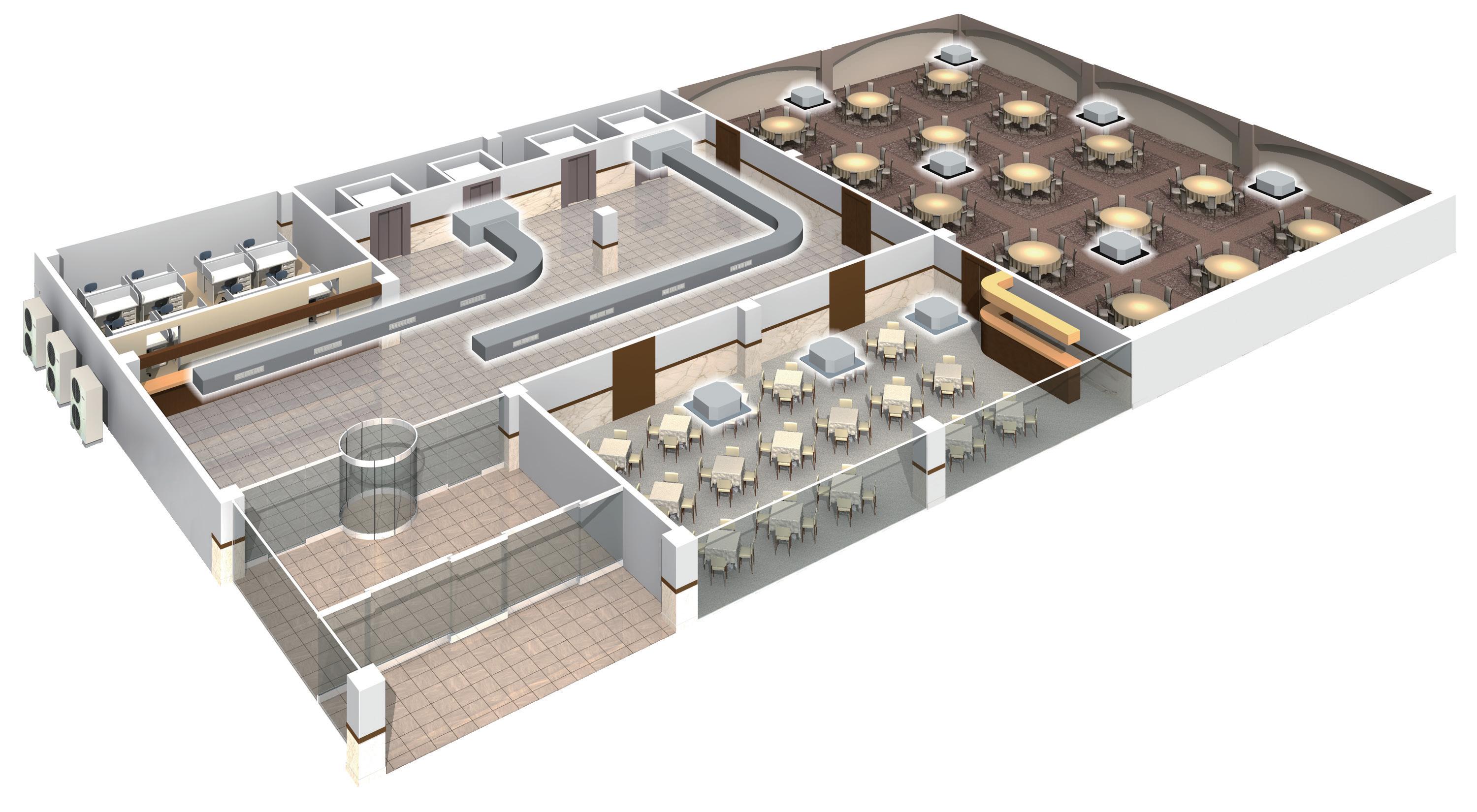
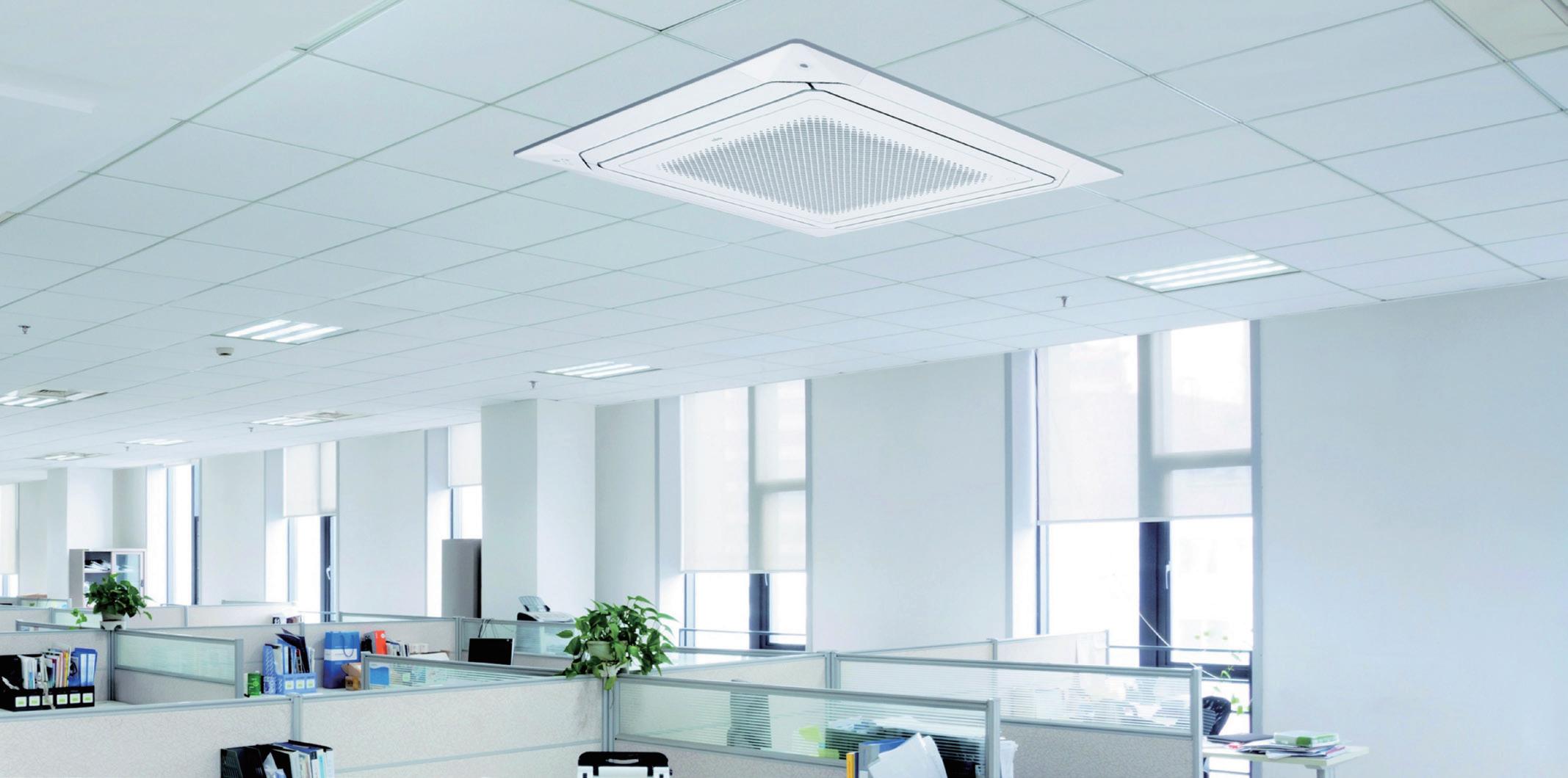
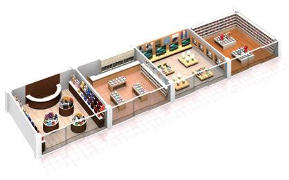
Fujitsu General provides a wide range of solutions designed to meet the needs of a small building. With energy saving features, low noise design and centralised control, this range is sure to meet your light commercial projects requirements.
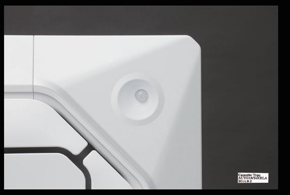
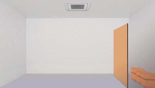
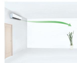
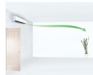
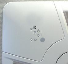
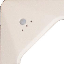
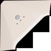
Energy saving features can be utilised with the human sensor feature and external input / output kit. This means unecessary power consumption will be prevented when no movement is detected in the room.

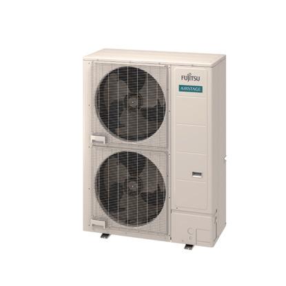
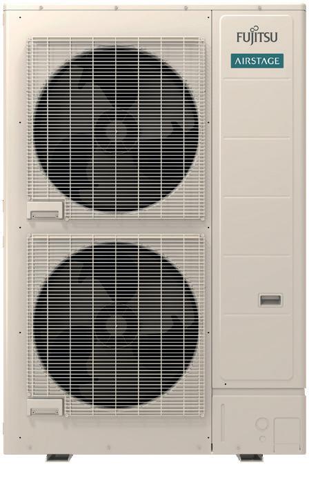
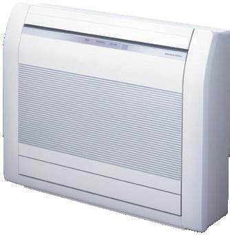
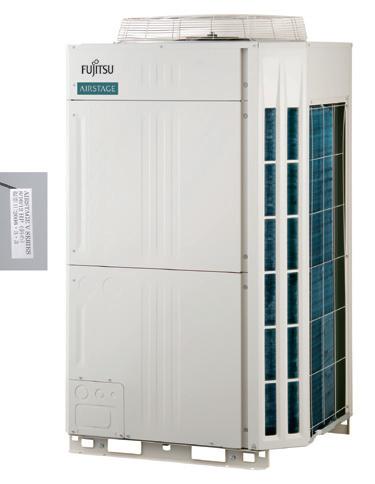
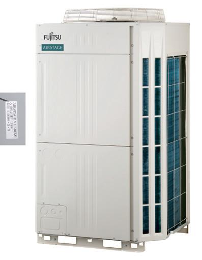
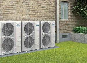
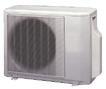
This compact outdoor unit achieves significant space saving, meaning you can install it on a rooftop or in a plant area. Low noise operation is possible at night by utilising low noise mode.
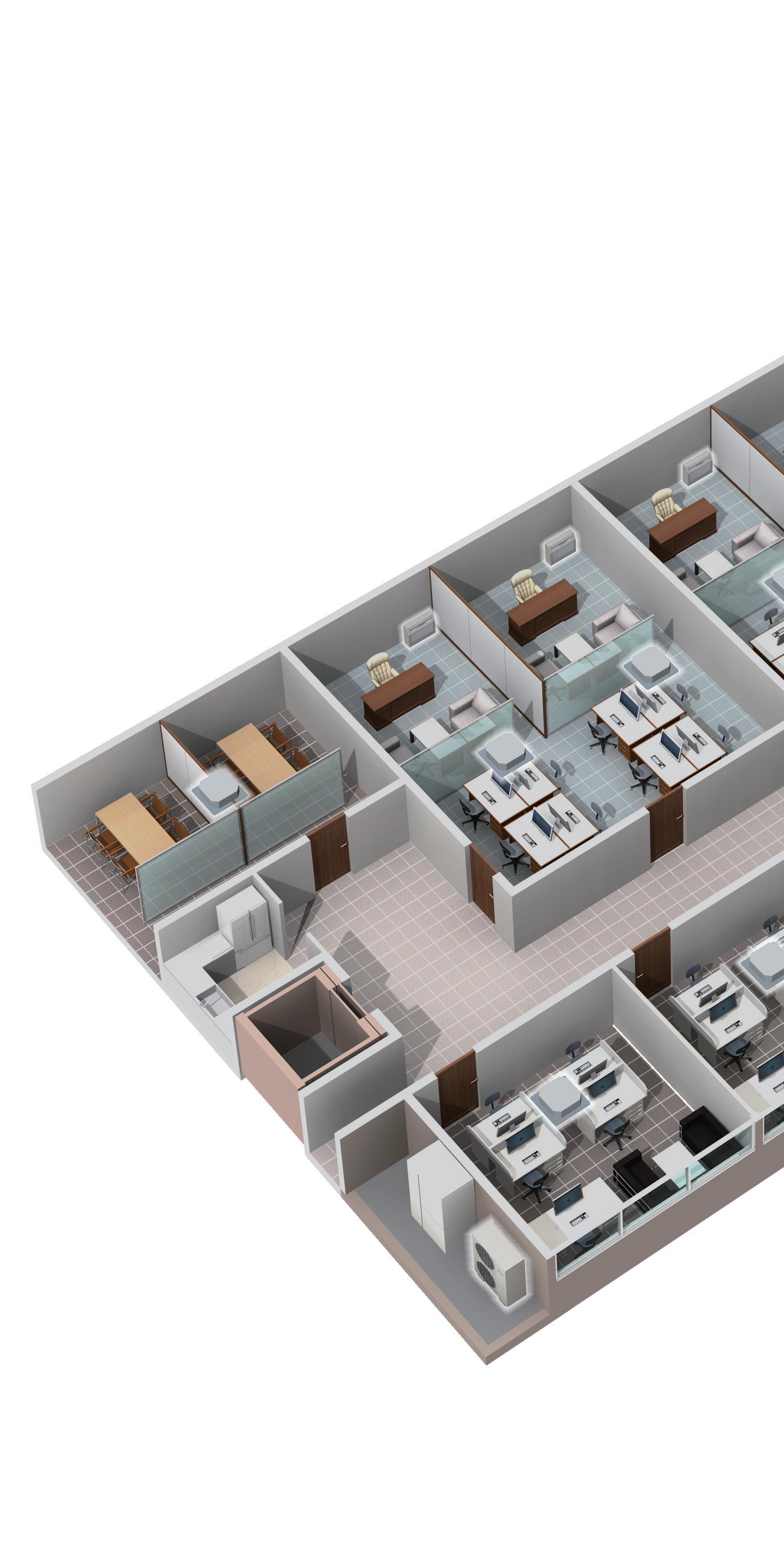
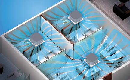
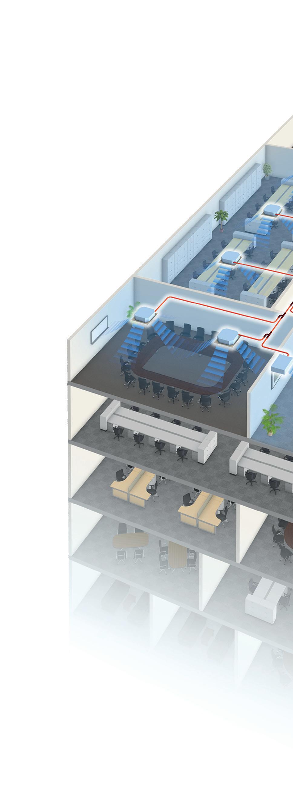
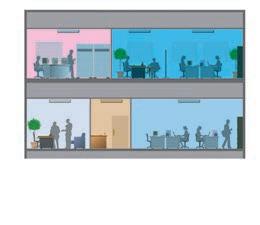
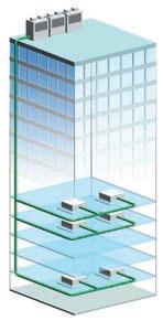
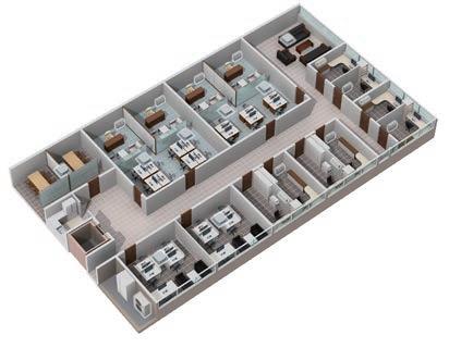
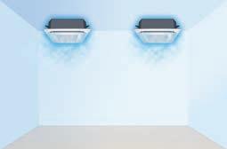
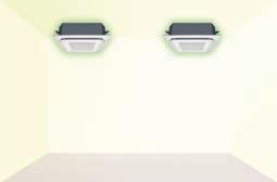
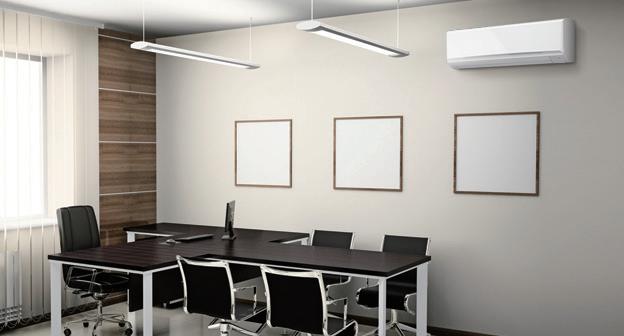
The J-IVL Series is suitable for the buildings with multiple small rooms. Maximum 30 indoor units can be connected.
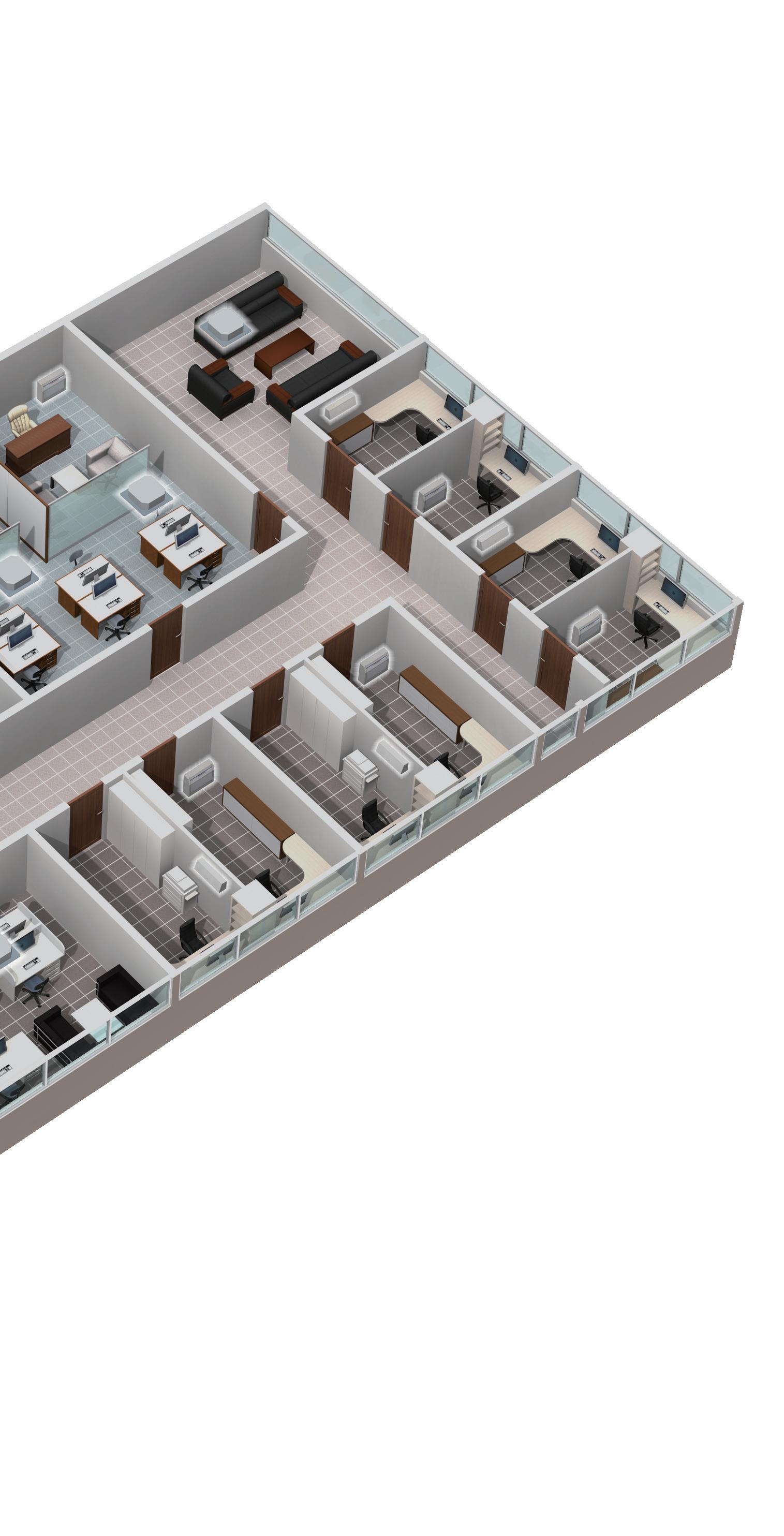
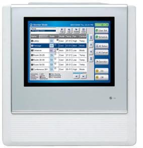
It is possible to perform centralised control of the air conditioning, including operation, scheduling and applying prohibits to local controllers.
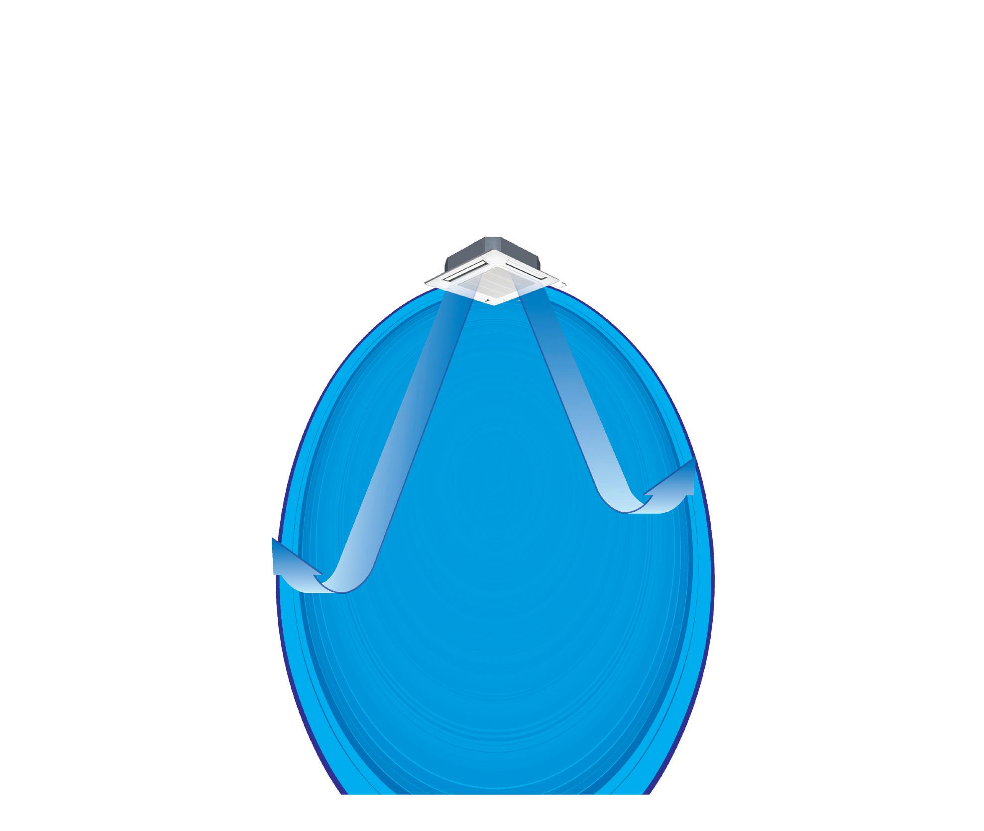
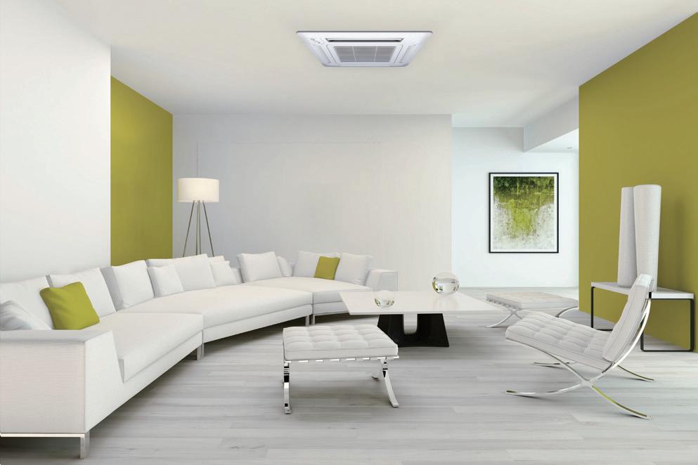
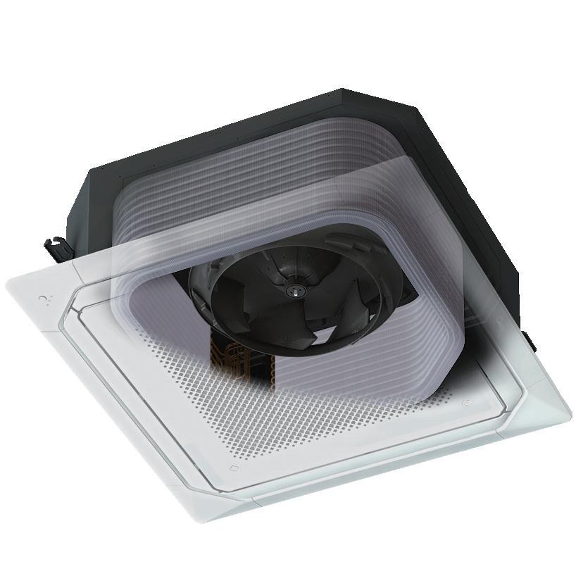
The Circular Airflow Cassette creates a consistent and even temperature via multi-directional airflow functionality.
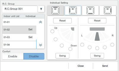
Each louvre can be set individually by the controller* to prevent people from being exposed to direct airflow.
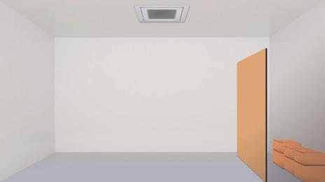
Energy saving operation commences when there are no occupants by linking up with the human sensor option. The unit will adjust its operation depending on the presence of occupants within a given room. The human sensor detects movement and activates or deactivates energy saving modes accordingly.

Extensive range of low capacity indoor units to suit small rooms or spaces.
Purpose built and tenant friendly solutions for small commercial complexes.
Air conditioning options for open areas
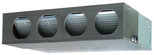
Large duct system suitable or appropriate for high ceiling and large open spaces


Air distribution design allows for circular airflow to spread to every corner of the room.
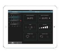
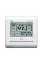
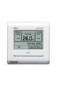
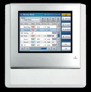
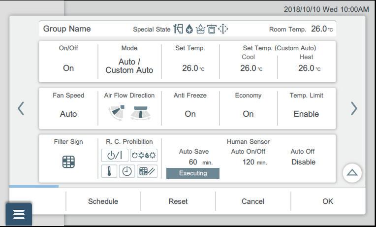
Temperature management of each room and one week operation control management / settings are supported easily. This controller makes energy saving management possible with upper / lower temperature limit settings and operation prohibited settings.
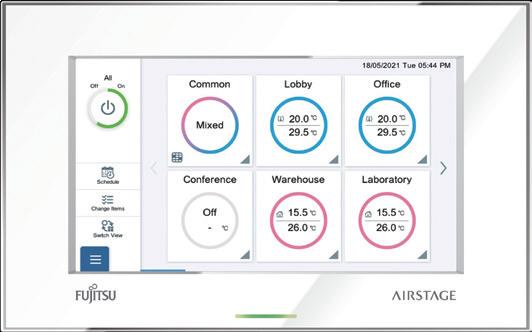
The controller allows high visibility and easy operation as all settings are accessible from the main screen. The controller can be monitored remotely using a tablet or smart phone through a web browser to show detailed information of an error status and the ability to view key sensor values for troubleshooting.

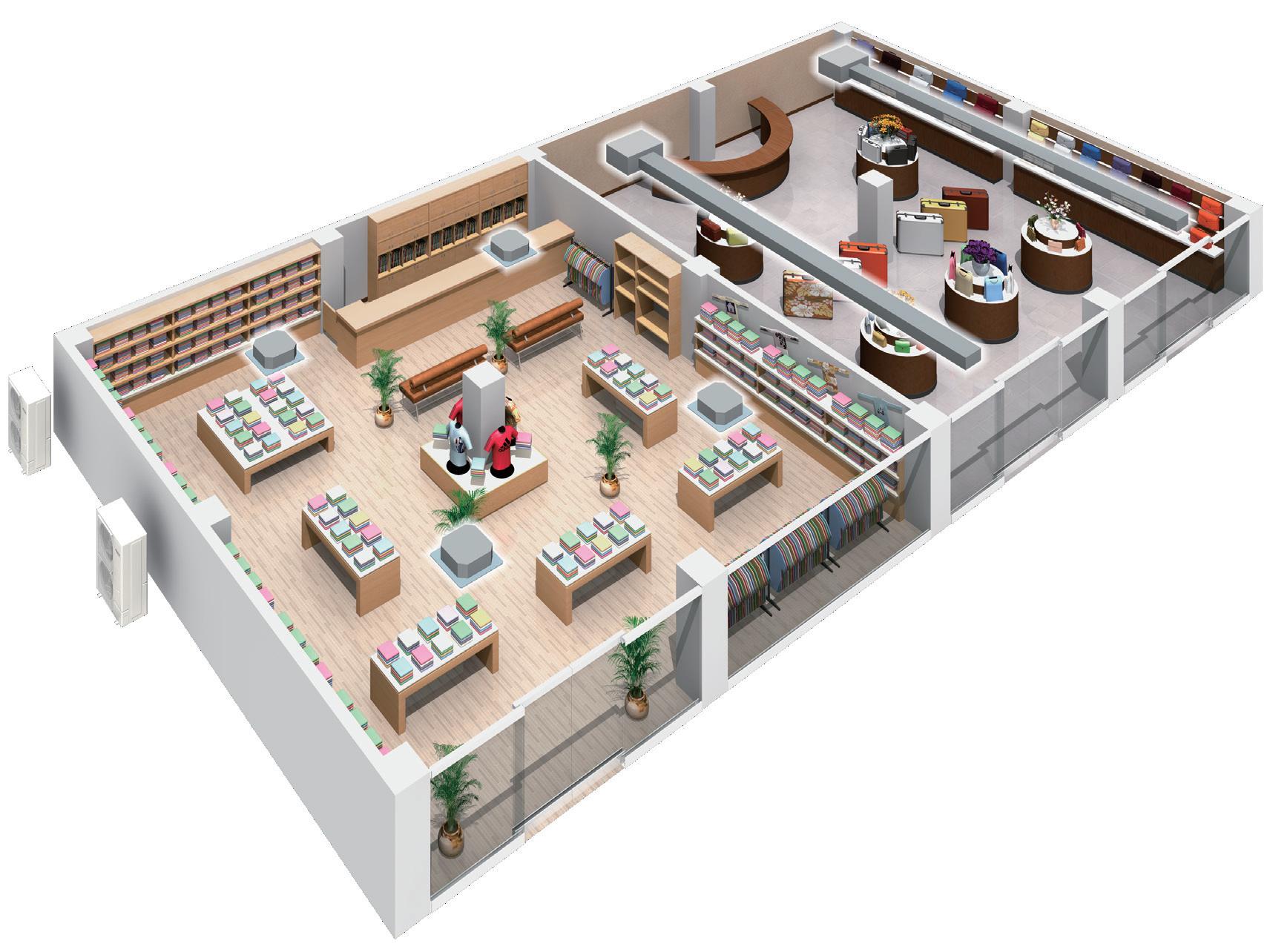
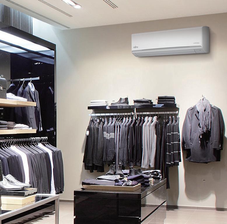
Low outside air temperature cooling operation is necessary in winter in stores with a lot of heat inside. Our air conditioning systems allow flexibility supporting cooling operation at -15°C.
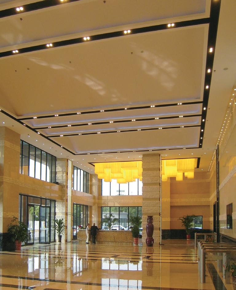
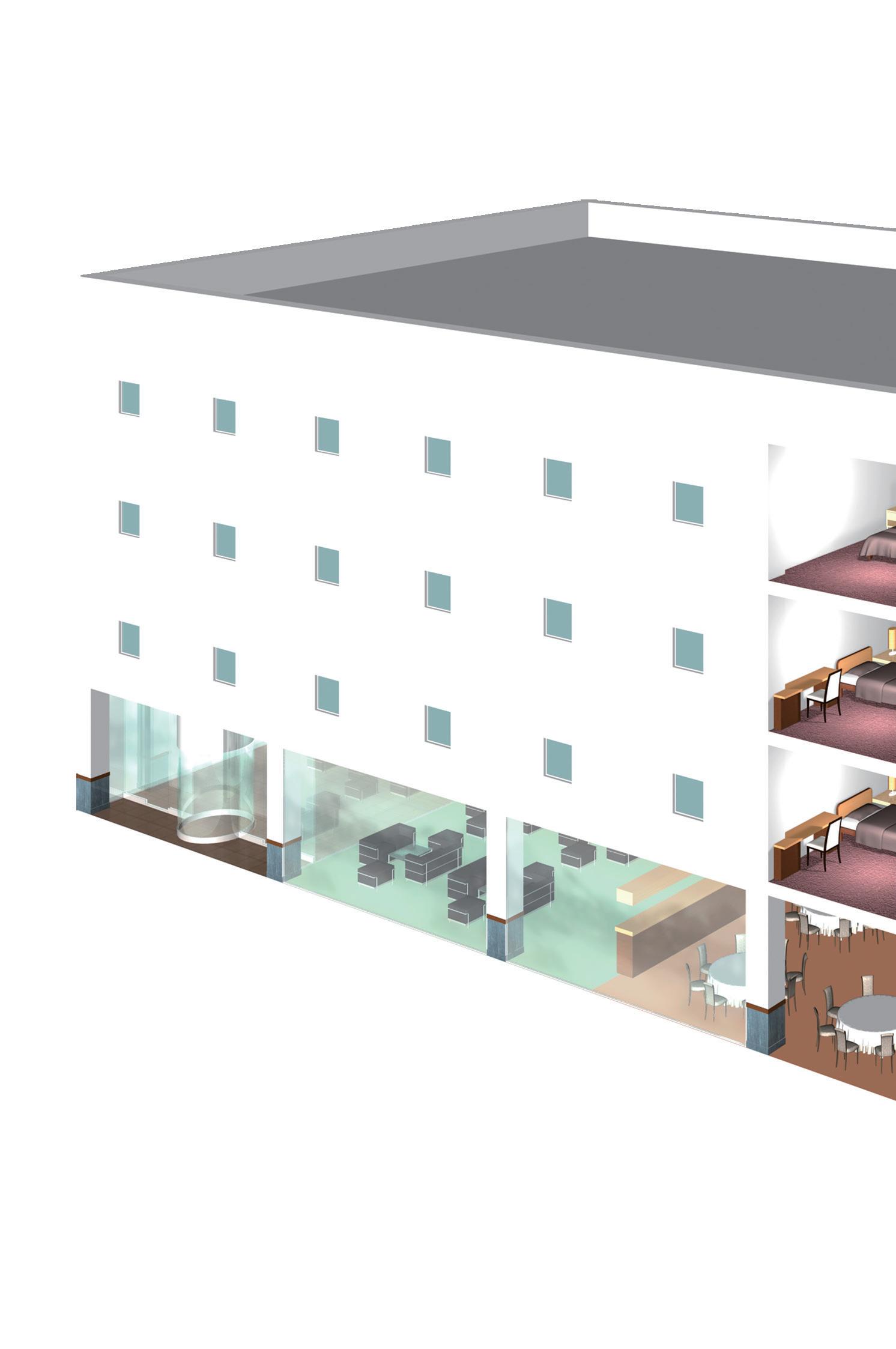
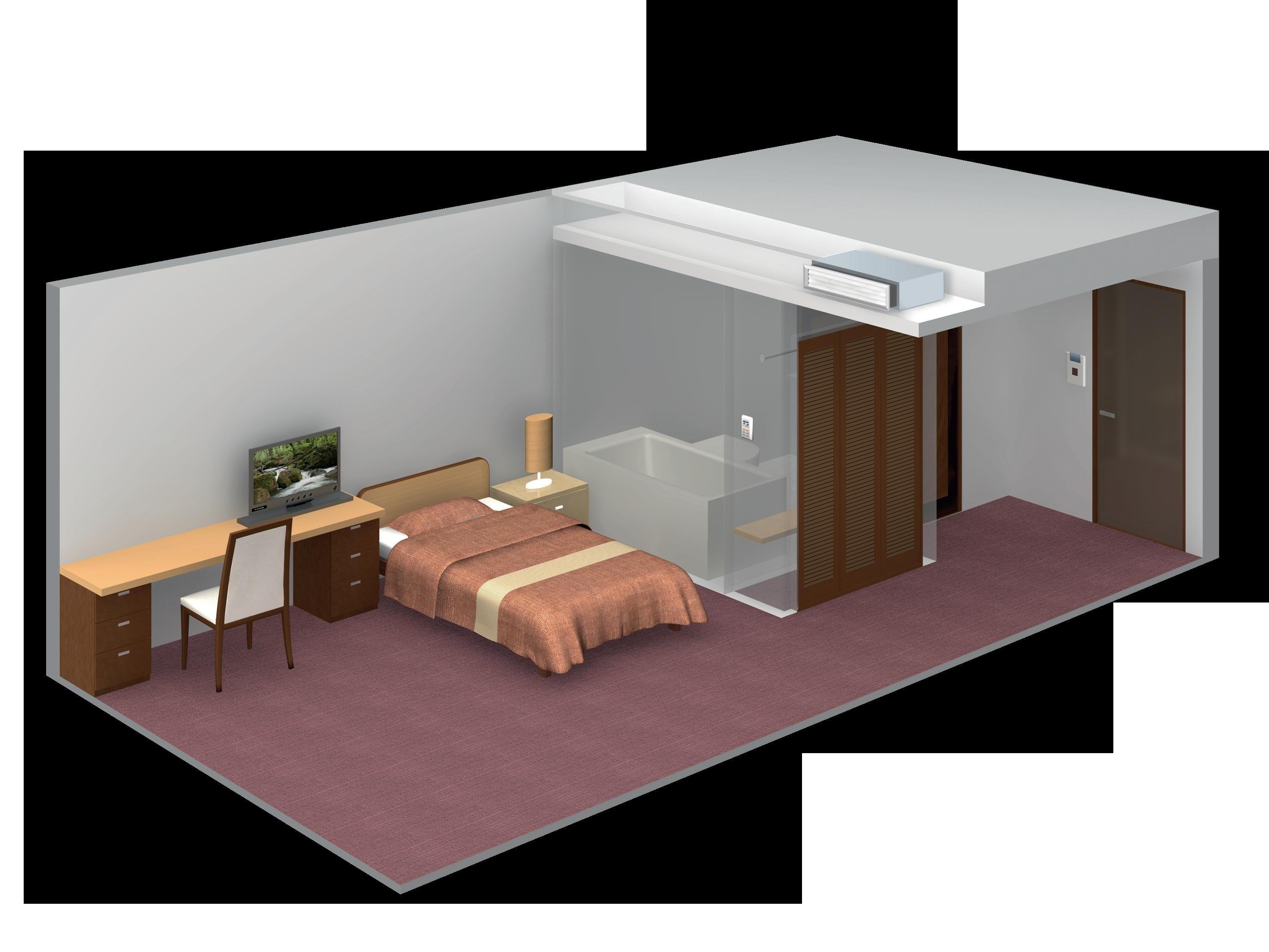
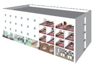
Fujitsu General provides energy saving air conditioning systems offering flexible installation and cutting edge design solutions for hotels and apartments that also take into account comfort, efficiency, external appearance, and system safety features.
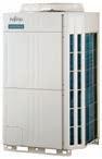
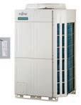
The VR-IV heat recovery series functionality allows simultaneous cooling and heating operation, with a maximum outdoor capacity of 48HP.

Smart and cutting edge design. Extensive lineup from 8 HP to 48 HP in 2 HP increments. Connectable indoor unit capacity ratio of 50 to 150%.
8HP-48HP 33 models
• Space saving combinations: 8HP to 48HP / 21 models
• Energy efficiency combinations: 16HP to 42HP / 12 models
High Static Pressure Duct suitable for large spaces with high ceilings

Outdoor-air Processing Units connect with the VRF System to meet ventilation requirements.
Space saving
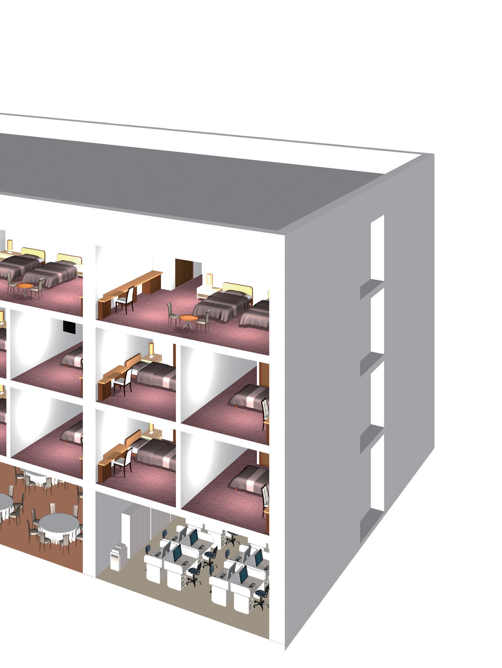
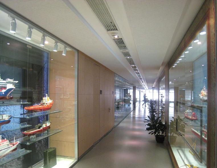
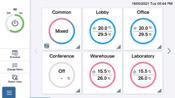
Air conditioning in shared spaces such as waiting areas and hallways can be controlled centrally. Temperature and operating conditions can be managed without manual adjustment by guests.
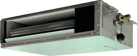
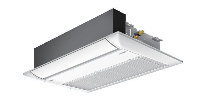
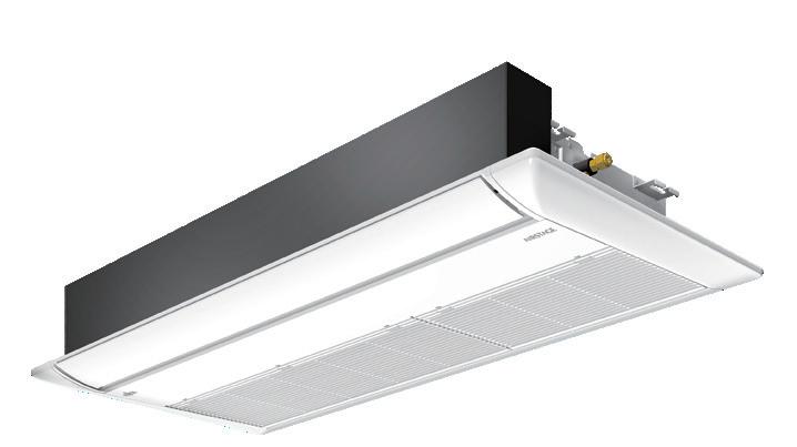
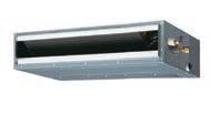
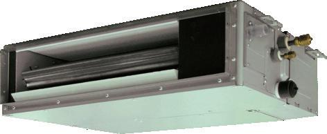
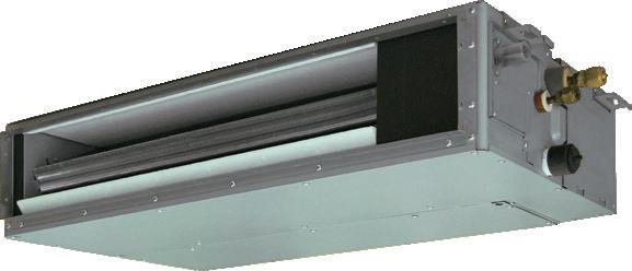
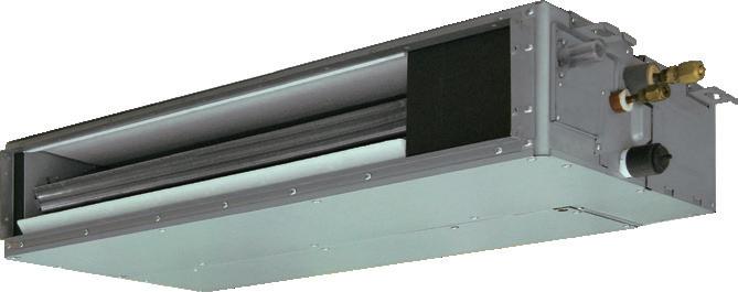
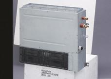
Mini duct type with 198mm height and 450mm depth. This can be installed in narrow ceiling spaces.
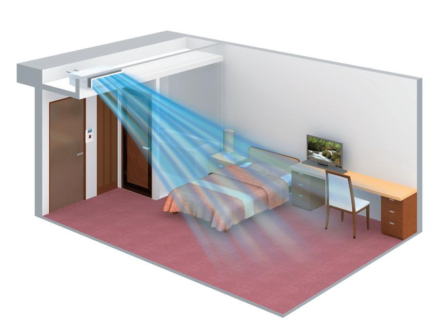
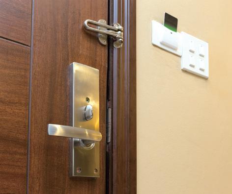
Room card switch
Using the room card prevents guests from forgetting to switch off the air conditioner when departing their room.
Comfortable airflow
The optional Auto Louvre Grille Kit achieves comfortable airflow by adjusting the direction of airflow.
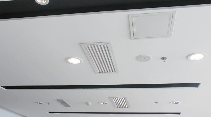
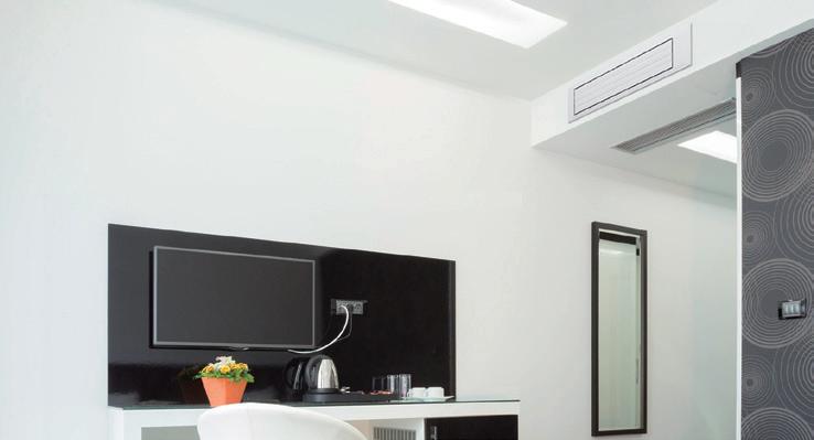
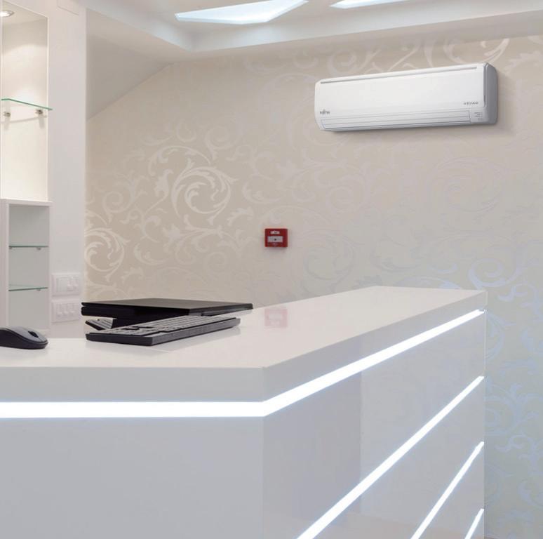
Their compact sizes make it easy to install them in a variety of commercial locations and environments. They produce little noise during operation, which makes them an ideal choice for use in hotel rooms.
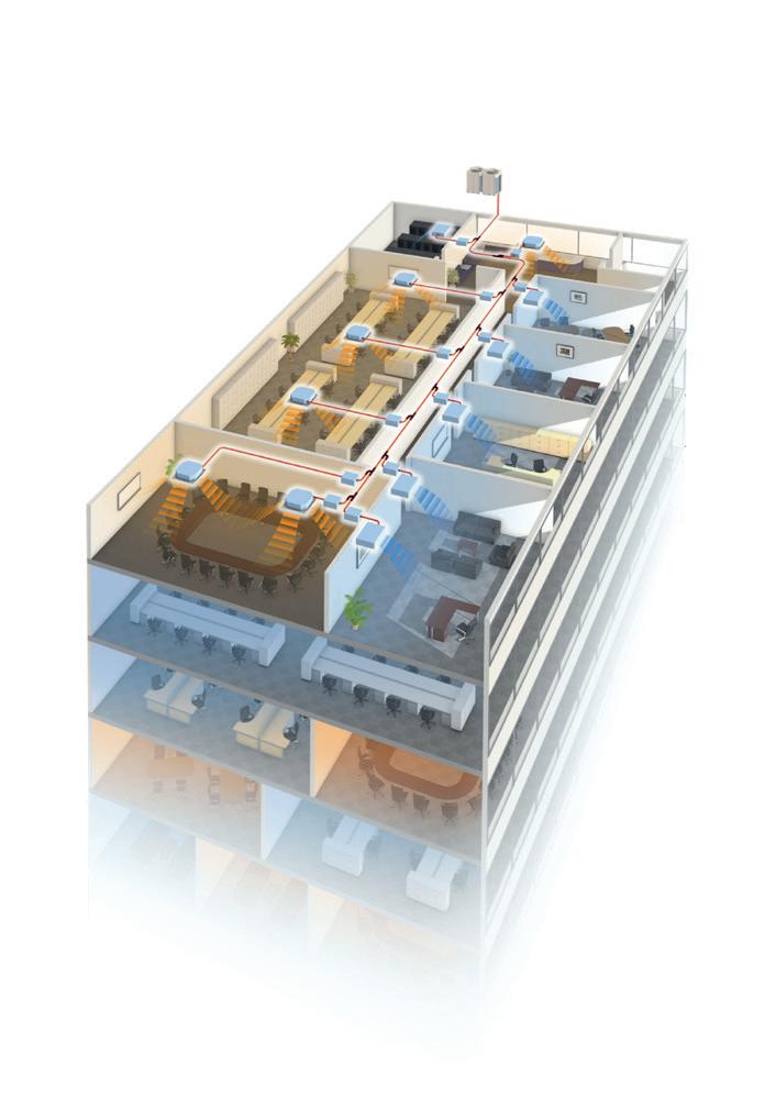
Fujitsu General provides modular VRF systems that are highly efficient, reliable and offer flexible installation for large or high rise buildings.
The VRF V-III Series lineup is designed to meet various needs with energy efficient models. These units are compatible with high outdoor air ambient temperatures.
Heat Pump Modular type for heating or cooling operation
8 HP - 48 HP 33 Models
• Space saving combinations: 8 HP to 48 HP / 21 models
• Energy efficiency combinations: 16 HP to 42 HP / 12 models
The height difference between the outdoor unit and the indoor unit is usually 50 m for the V-III Series, but by installing the pressure sensor kit it is possible to expand it to 110 m.
(*This product can only be used connected to the V-III Series.)

It is possible to centrally control the air conditioners including operation and
System Controller
UTY-APGXZ1
System Controller Lite
UTY-ALGXZ1

integration
and scheduling.
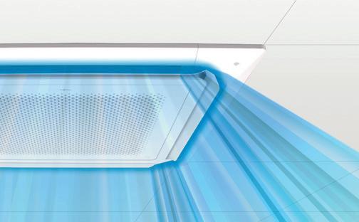
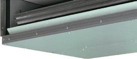
Improved airflow distribution
The unique design of the louvres and added space between the chassis and ceiling maximises airflow distribution within the room.
Major protocols including Modbus, BACnet, KNX and LonWorks are supported, allowing Fujitsu AIRSTAGE™ equipment to be easily integrated using one of our gateway options.
High ceiling mode
This cassette can be installed up to a ceiling height of 4.2m (36/45/54).


HIGH ENERGY EFFICIENCY
MAXIMISED COMFORT
CONSISTENT RELIABILITY
DESIGN FLEXIBILITY
EASY INSTALLATION
EASY SERVICE & MAINTENANCE


Energy Efficiency Comparison
Operational efficiency has improved significantly through the new DC twin rotary compressor, inverter technology and large heat exchanger.
The minimum and maximum temperature ranges can be limited, which provides further energy saving functionality whilst maintaining the comfort of the occupants.
The wired remote controller is equipped with an OFF timer function that automatically stops the units operation when a fixed time has elapsed from the start of operation. The schedule for the auto off timer can be programmed.
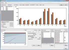
A variety of energy saving operations can be set and managed depending on the season, weather and time period using the System Controller and a third party watt hour meter.
Operation capacity can be set in 5 simple steps for rated capability. The power consumption at peak is cut down and the maximum load is suppressed.


Fujitsu General proposes an outdoor unit which includes new refrigerant control. Refrigerant control can be operated with suitable control corresponding to heat load of the room and can offer a more comfortable space. Refrigerant control can also provide more energy savings.
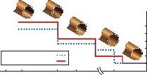
Thermostat-ON/OFF occurs frequently. The comfort is not good since room temperature often changes. Energy saving is not good since compressor is repeated starting and stopping frequently.
Room temperature is maintained as thermostat ON/OFF is reduced achieving improved refrigerant control. Energy saving is improved as the compressor continues operation for a longer time than old control.
* Available for AIRSTAGE VR-IV, J-IVL, J-IV and J-IVS


* The improvement by the control and the actual sine wave varies by the combination of the indoor unit and system operating condition.
Precise and smooth refrigerant flow control is achieved by using the DC Inverter control in conjunction with an individual indoor unit electronic expansion valve. This allows the set temperature to be controlled ±0.5°C.


Two low noise modes can be selected automatically through the ‘quiet priority setting’ and ‘capacity priority setting’ depending on the noise or capacity requirements. This feature can be controlled via an outdoor unit external input and / or System Controller.
When the auto setting is selected, the unit automatically switches between cooling and heating modes according to the set temperature and room temperature.
The auto change over setting allows for the product to easily switch between cooling and heating modes regardless of the operation mode of the other indoor units. This can be done via a specific indoor unit with a wired remote controller. This ensures comfortable operation all year round.
*: Only available on VR-IV
A comfortable room temperature is maintained during the oil recovery mode as the unit continues to operate without stopping the cooling or heating operation.
*: Not available on the AIRSTAGE VR-IV


The compressor starting order is rotated so that the running time is shared.
If one compressor fails, backup operation will be performed by the remaining compressors*.
* Note: Backup operation may not be possible depending on the system error.
Innovative compressor control logic has been introduced in order to balance the refrigerant mass flow rate of each outdoor unit by controlling the inverter speed.
Through a larger accumulator, the non vapourised refrigerant stays within the accumulator to ensure no liquid refrigerant is being fed into the compressor.
The corrosion resistance of the outdoor heat exchanger has been improved by the introduction of blue fin treatment.


* The limitation on the pipe length between the farthest
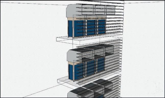
The outdoor unit can have a condenser hood easily connected with a static pressure up to 82Pa. This allows outdoor units to be installed within plant rooms in high rise buildings.
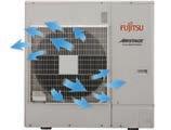
Powerful discharge of air prevents a short-circuit.


Installation in extreme temperature conditions is possible due to an increase in operational range.
*1. Note: When a multiple outdoor unit connection is used, operating range is from -5°C to 46°C in cooling.
*2. The

Easily craned using lifting belt hooks
Design of outdoor unit allows for lifting straps to be used.
Transporting by forklift
Transport with forklift is possible.
Can be transported in a small elevator
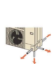
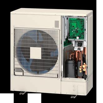
By adopting an L-Shape front panel that can be removed, the work space for installation and service has been significantly improved by this new design.
Piping and wiring are available to the front, rear, bottom and side.
Installation of the wiring is made easier as the communication wiring can be installed in a series or parallel configuration between the indoor, outdoor and RB units.
The vacuum mode function enables all expansion valves of the indoor units to be fully opened, making it easy to evacuate all the air inside pipe lines and indoor units.


The address of the indoor unit, RB unit and signal amplifier can be set through the automatic function setting on the outdoor unit PCB.


• Service Tool (UTY-ASGXZ1)
The Service Tool checks the refrigerant temperature and pressure, and the operating status of the electronic expansion valves, making it easy to determine if the units are connected properly.

• Central Remote Controller (UTY-DCGYZ3)
The Service Tool checks the refrigerant temperature and pressure, and the operating status of the electronic expansion valves, making it easy to determine if the units are connected properly.


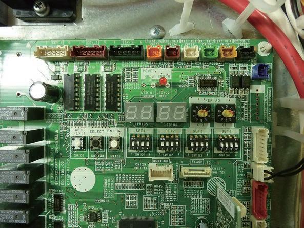
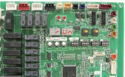
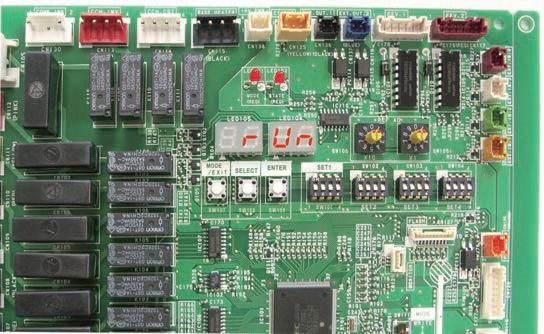
Self diagnosis can be performed using the LED display which makes it easy to check function setting status, refrigerant temperature, pressure, compressor operation time and other factors.
Easy to read 7 segment LED : Provides detailed operational and error status without using any specific equipment.
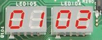
7 segment LED
• Operation mode status
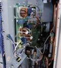
Movable PCB panel Easier for maintenance work behind the PCB
• Discharge temperature / pressure status
• Compressor operation indication
• Address / type / number of outdoor units


• Detail operation status and recent error history can be checked and analysed by using the Service Tool.


Remote monitoring
The Web Monitoring system allows you to view system operation anytime over the internet in real time.


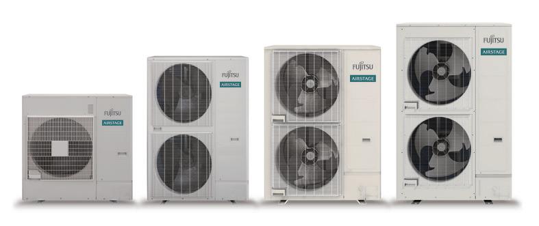
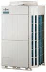
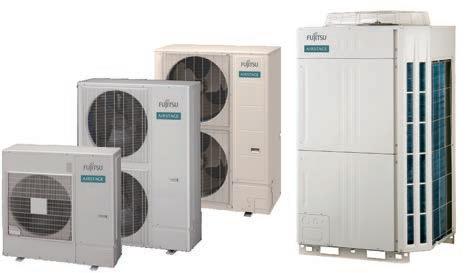
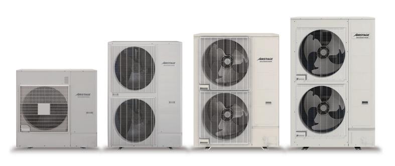
The 5 series of the AIRSTAGETM range has a total of 78 outdoor models to meet the project scope or building size requirements

The AIRSTAGE™ Series outdoor units have been developed with structural designs and advanced inverter technology to provide higher efficiency. High durability technology has also been incorporated to ensure long-term use.
HEAT PUMP TYPE AIRSTAGE™ J-IVS
HEAT PUMP TYPE AIRSTAGE™ J-IV
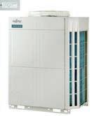
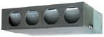
HEAT PUMP TYPE AIRSTAGE™ J-IVL
HEAT PUMP TYPE AIRSTAGE™ V-III
HEAT RECOVERY TYPE AIRSTAGE™ VR-IV


System configuration example
• This system is used for small and mediumsized buildings. 1 refrigerant system is used for each outdoor unit.
• Connection of multiple indoor units using separation tubes and headers.


Intelligent refrigerant control can be operated with suitable control corresponding to heat load of the room and can offer a more comfortable space. Intelligent refrigerant control can also provide more energy savings.
Previous model (J-IIS)


Outdoor unit supplies constant capacity regardless of indoor unit request
static pressure
External static pressure is available up to 25Pa for 4/5/6HP.
Current model (J-IVS) Outdoor unit supplies adequate capacity on demand from indoor unit
* The improvement by the control and the actual sine wave varies by the combination of the indoor unit and system operating condition.
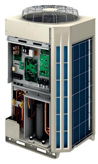
high efficiency technology
Large propeller fan
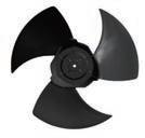
High performance and low noise realised by the large propeller and angle optimisation.
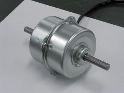
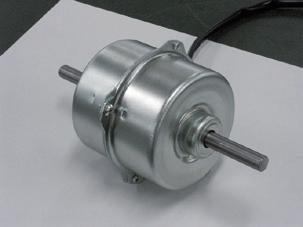
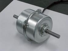
DC fan motor
The outdoor unit utilises a miniaturised, high efficiency, multi-stage DC fan motor.

Large heat exchanger
Heat exchange performance is substantially improved by the use of a 3-row large heat exchanger.


Smooth airflow grille
The
DC inverter control
Efficiency is improved through the new active filter module.
Efficiency is delivered in all load regions particularly when at low to medium load requirements.
Our advanced refrigerant control technology allows us to achieve a total refrigerant piping length of 80 m. This opens up possibilities in system design.
The combination of the smallest but adequate capacity indoor unit and a new outdoor unit with the optimum heat exchanger structure has realized the industry’s top class connection of 13 units.
*: 6 HP model
With the connection check function it is possible to confirm whether the wiring connection and address settings are correct.


• Display connected indoor unit numbers
• Duplicate set address numbers of indoor unit can be identified
A comfortable room condition is maintained during oil recovery mode because the product continues to operate without stopping the cooling or heating operation.


Using the optional part UTY-XCZXZ1 this unit can be controlled through Demand Response functionality.


4HP : AJT040LCLCH
5HP : AJT045LCLCH
6HP : AJT054LCLCH
Note: Specifications are based on the following conditions:
Cooling: Indoor temperature of 27°CDB / 19°CWB, and outdoor temperature of 35°CDB / 24°CWB.
Heating: Indoor temperature of 20°CDB / (15°CWB), and outdoor temperature of 7°CDB /
6°CWB.
Pipe length: 7.5m; height difference between outdoor unit and indoor unit: 0m. These are the measured values in the manufacturer’s anechoic chamber. Because of the surrounding sound environment, the sound levels measured in actual installation conditions might be higher than the specified values here.
System configuration example
• This system is typically used for small and medium-sized buildings
• This example shows the connection of multiple indoor units using separation tubes and headers

Intelligent refrigerant control can be operated with suitable control corresponding to heat load of the room and can offer a more comfortable space. Intelligent refrigerant control can also provide more energy savings.
Previous model (J-III)
Outdoor
Current model (J-IV)
Outdoor unit supplies adequate capacity on demand from indoor unit
* The improvement by the control and the actual sine wave varies by the combination of the indoor unit and system operating condition.
static pressure
External static pressure is available up to 30Pa for 4/5/6HP.
high efficiency technology
Large propeller fan
High performance and low noise is realised by the large propeller and angle optimisation.

The

Large
Heat exchange performance is substantially improved by the inclusion of a 3-row

inverter control
Efficiency is improved through the new active filter module.
Subcool heat exchanger
Cooling performance is improved from the dual tube heat exchanger.
Efficiency in all load regions is consistent, especially when meeting low to medium load requirements.
The high COP is achieved for all models through a large heat exchanger, highly efficient DC twin compressor and our own technologies.
Our advanced refrigerant control technology allows us to achieve a total refrigerant piping length of 180m, opening up new possibilities in system design.
Up to 10 units* can be connected The combination of the smallest but adequate capacity indoor unit and a new outdoor unit with the optimum heat exchanger structure has realized the industry’s top class connection of 10 units.
*: 6 HP model
A comfortable room condition is maintained during oil recovery mode because the product continues to operate without stopping the cooling or heating operation.
With the connection check function it is possible to confirm whether the wiring connection and address settings are correct.
Using the optional part UTY-XCZXZ1 this unit can be controlled through Demand Response functionality.


Note: Specifications are based on the following conditions:
Cooling: Indoor temperature of 27°CDB / 19°CWB, and outdoor temperature of 35°CDB / 24°CWB.
Heating: Indoor temperature of 20°CDB / (15°CWB), and outdoor temperature of 7°CDB /
System configuration example
• This system is typically used for small and medium-sized buildings
• This example shows the connection of multiple indoor units using separation tubes and headers
Intelligent refrigerant control can be operated with suitable control corresponding to heat load of the room and can offer a more comfortable space. Intelligent refrigerant control can also provide more energy savings.
Previous model (J-IIIL)
Outdoor unit supplies constant capacity regardless of indoor unit request
External static pressure is available up to 60Pa for 14/16HP. (30Pa for 8/10HP, 40Pa for 12HP)
Current model (J-IVL)
Outdoor unit supplies adequate capacity on demand from indoor unit
* The improvement by the control and the actual sine wave varies by the combination of the indoor unit and system operating condition.
* Capacities are slightly decreased for rated values during high static pressure operation. 60Pa
570 mm
Large propeller fan
High efficiency and low sound operation is achieved by the reduction of draft loss due to Fujitsu General's blade design and large diameter propeller fan.
DC fan motor
The outdoor unit utilises a miniaturised, high efficiency, multi-stage DC fan motor.
Large heat exchanger
Heat exchange performance is substantially improved by mounting a 2-row large heat exchanger.
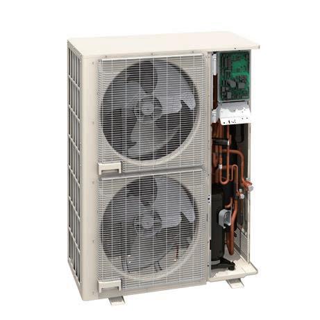
DC inverter control
Efficiency is improved by the use of a new active filter module.
Subcool heat exchanger
Cooling performance is improved by utilising a dual tube heat exchanger.
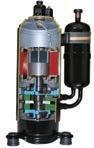
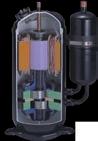
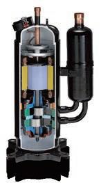
Scroll compressor
The scroll compressor has a wide range of rotational frequencies from 15 to 120 rps.
Fujitsu General's unique sensorless sine wave control method enables smooth control of the input power into the motor improving the energy efficiency operating characteristics and the low sound operation.
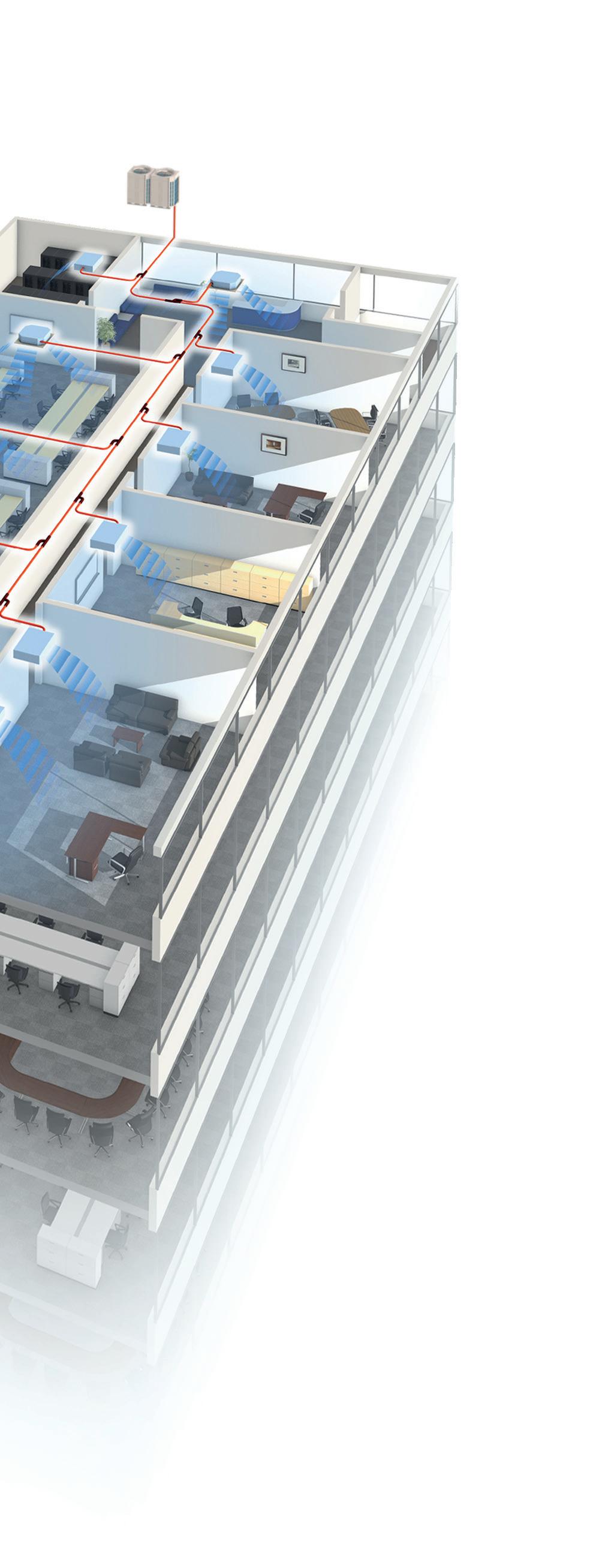
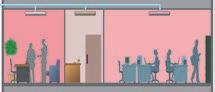
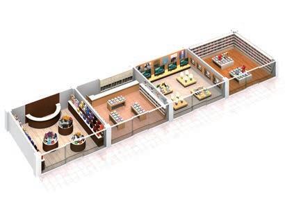
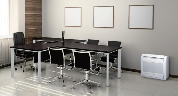
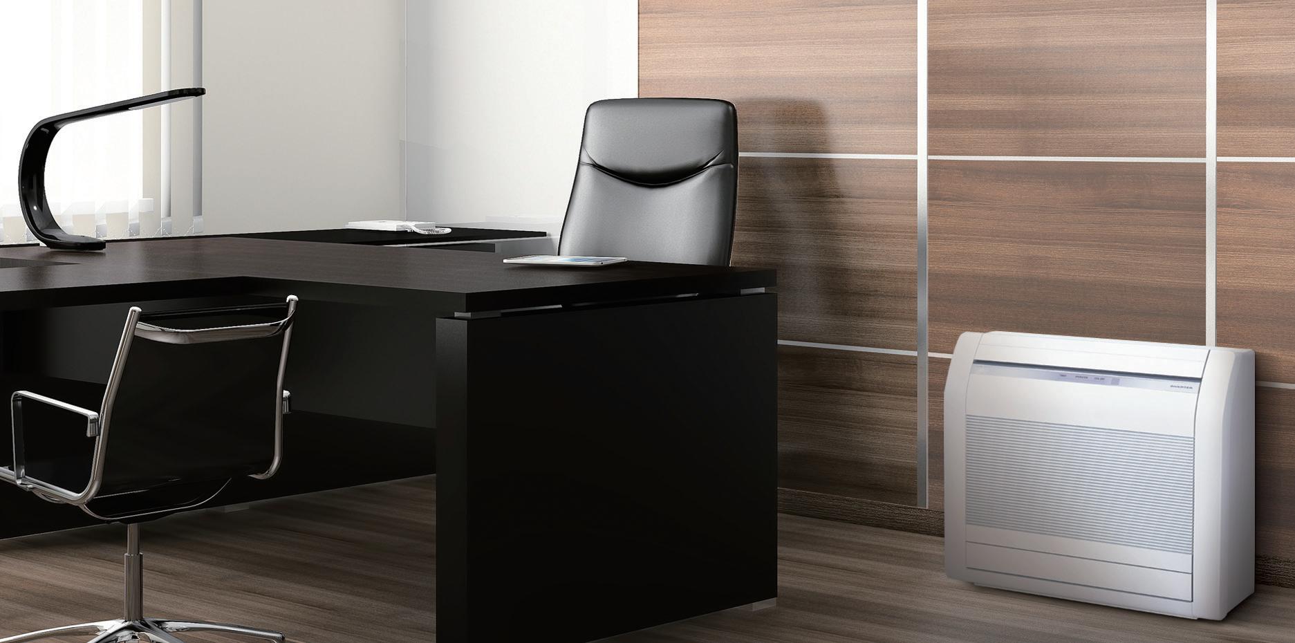
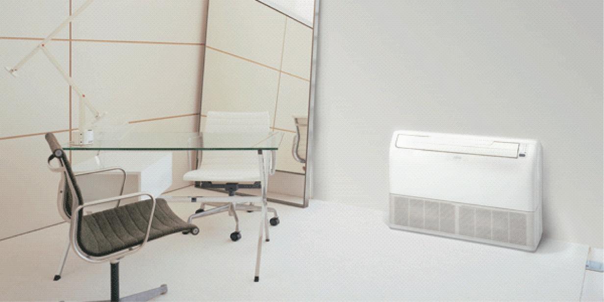
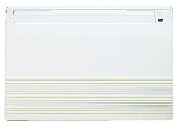
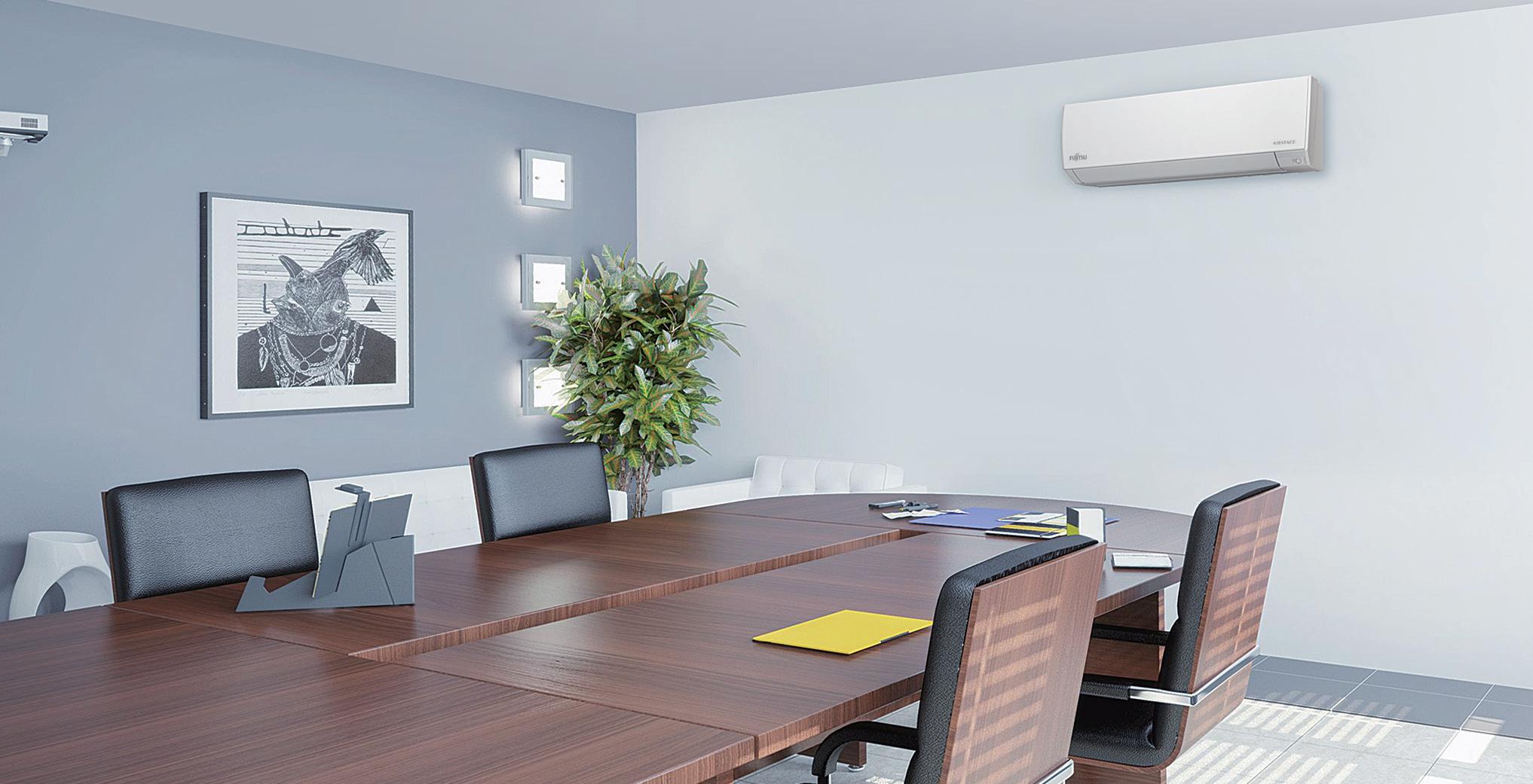
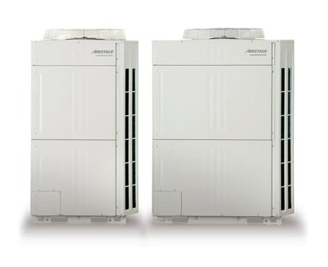
Fujitsu General provides perfect total air conditioning systems that take into account energy saving, low noise, comfortable airflow, small room application and centralized control for small-sized office buildings with many small rooms.
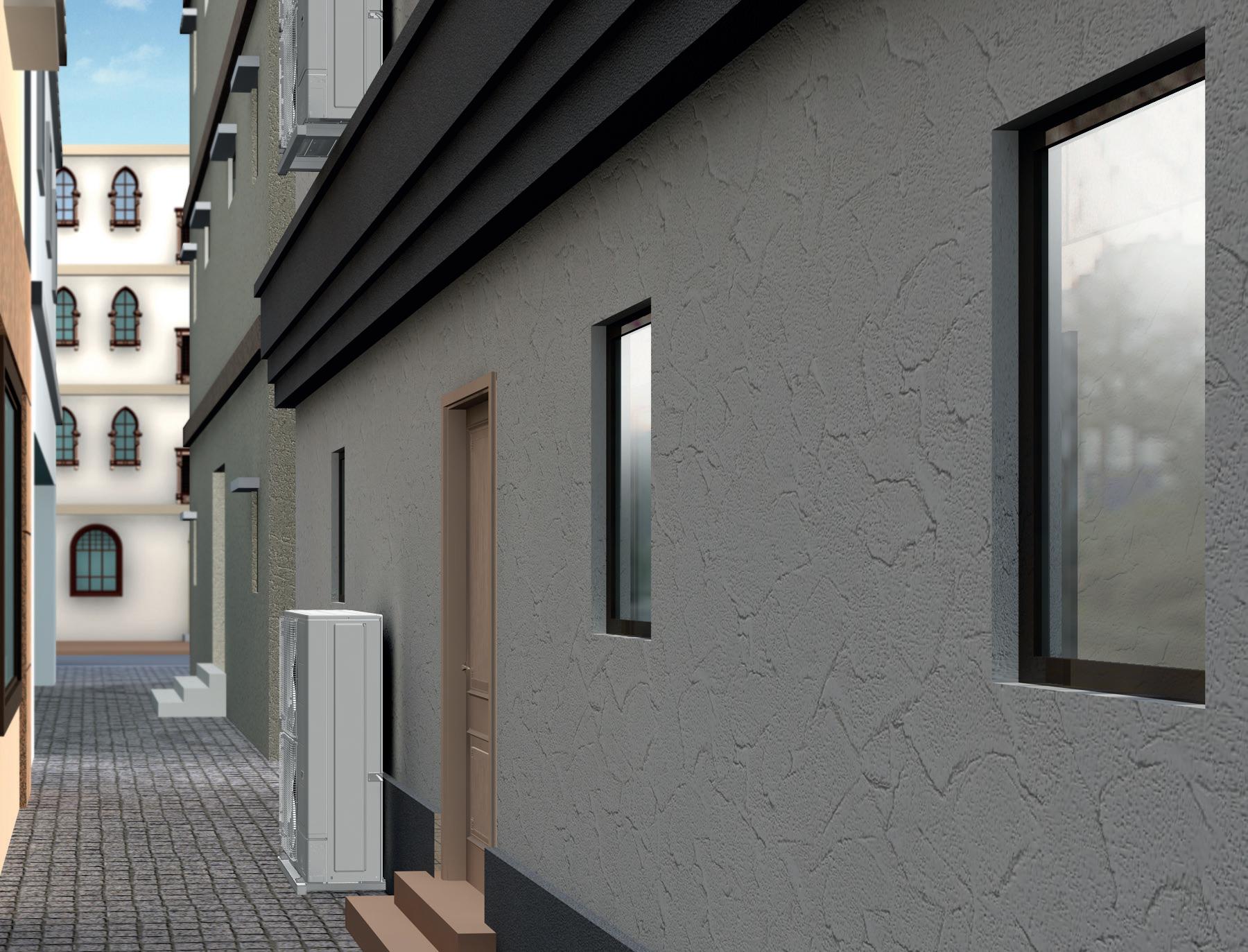

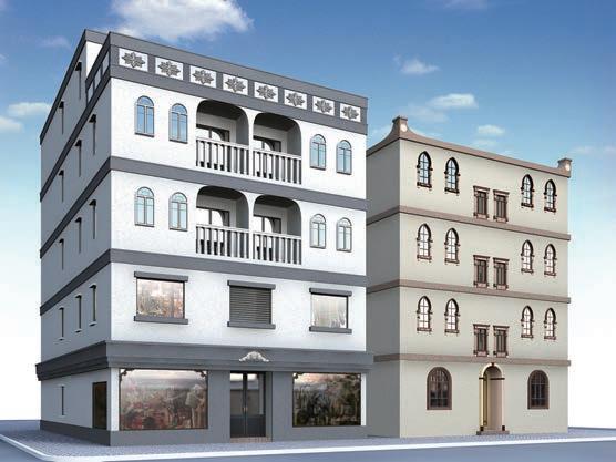
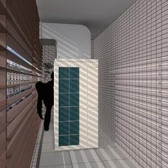
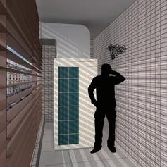
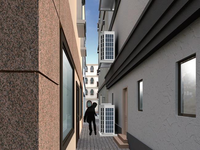
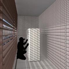
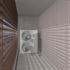
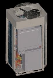
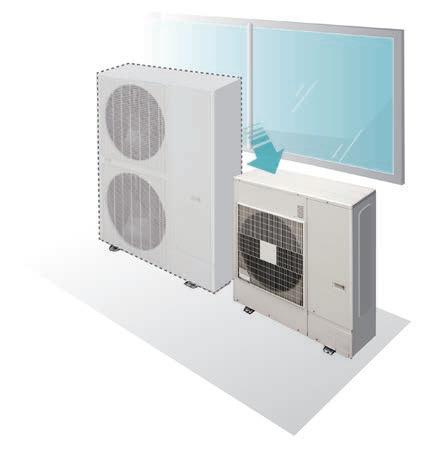
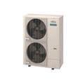
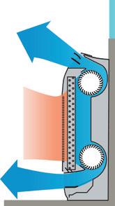
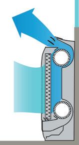
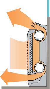
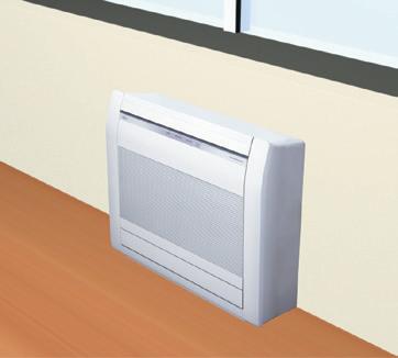
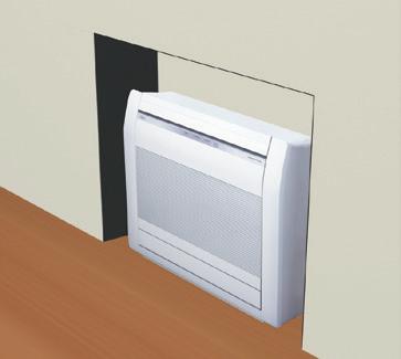
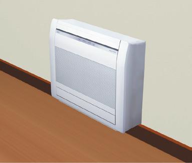
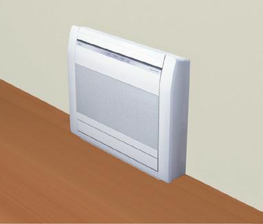
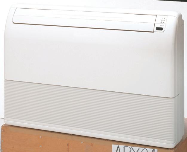
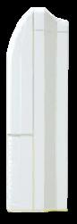
This model is front air discharge type and about 1000 mm wide, so flexible installation is possible even at narrow in house space.
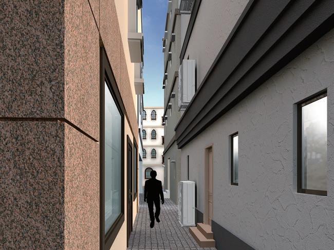
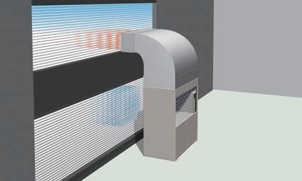
Narrow space behind building
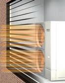
Due to compact and thin model, direct ground installation or wall mounted installation is possible even at narrow off-street.
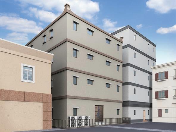
Installation at back street of building
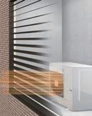
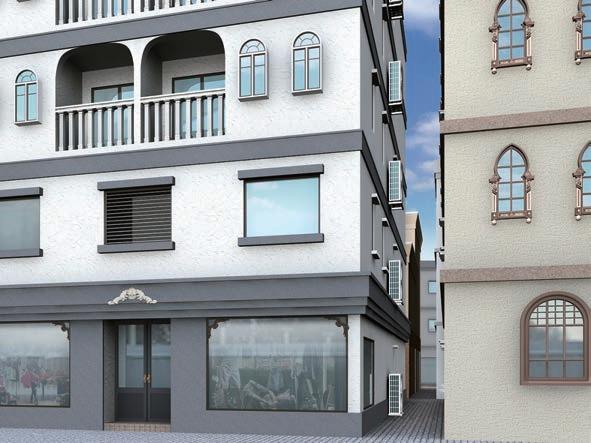
This model is front air discharge type and slim & low body, so installation space is compact. Building windows are not blocked and space saving multiple units installation is possible.
Top class high EER / COP is achieved for all models by large heat exchanger, highly efficient DC twin compressor, and our own technologies.
Our advanced refrigerant control technology allows us to achieve a total refrigerant piping length of 400m.
The combination of the smallest but adequate capacity indoor unit and a new outdoor unit with the optimum heat exchanger structure has realized the industry’s top class connection of 30 units. *: 16 HP model
Low operating sound makes this unit highly suitable to densely populated areas.

Since the demand response function is installed, the new model can operate with less energy when the electric power company notifies of a power shortage.
14HP :
16HP : AJY144LELBH
Note: Specifications are based on the following conditions:
Cooling: Indoor temperature of 27°CDB / 19°CWB, and outdoor temperature of 35°CDB / 24°CWB.
Heating: Indoor temperature of 20°CDB / (15°CWB), and outdoor temperature of 7°CDB /

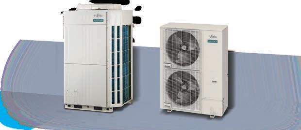
Modular Type

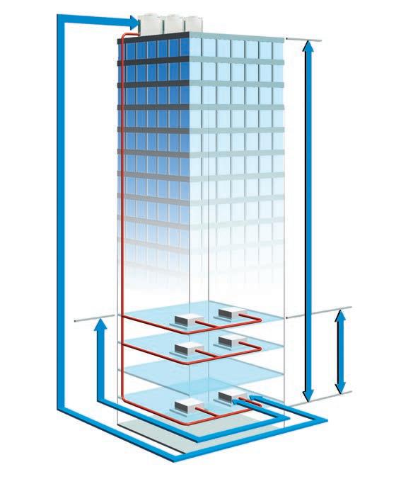
System configuration example
• This system is used for medium and large sized buildings. Connecting a combination of outdoor units makes it possible to create a high-capacity system.
• This example shows the connection of multiple indoor units using separation tubes and headers.


The refrigerant control operates with subtle control corresponding to the heat load of the room and offers a more comfortable environment. The refrigerant control can also provide increased energy savings.
Old model (V-II)
The outdoor unit supplies constant capacity regardless of the demand of the indoor unit.
Current model (V-III)
The outdoor unit provides sufficient capacity to meet the demands of the indoor unit.
* The improvements due to the control and the actual sine wave vary depending on the combination of the indoor unit and system operating conditions.
*Intelligent Refrigerant Control available for V-III series outdoor with serial number that starts with R4.
A high COP is realised for all combinations by our unique heat exchanger structure, highly efficient DC twin compressor and additional proprietary technologies.
* These specifications are determined by Cassette combination.

Powerful large propeller fan
By using CFD* 1 technology, the newly designed fan achieves high performance and low noise operation.
*1. CFD = Computational Fluid Dynamics

Sine-wave DC inverter control
High efficiency is realised by adoption of reduced switching loss IPM.

Subcool heat exchanger
High heat exchanger efficiency is achieved by using an internal projection shape with double pipe construction.

Large capacity ALL DC inverter compressor
The large capacity highly efficient DC twin rotary compressor with 0.1Hz steps compressor speed control


3 phase DC fan motor
Efficiency is improved with the highly efficient motor with sophisticated drive control. Additionally, the DC fan motor exhibits a low noise output.
4-face heat exchanger
Heat exchange efficiency is significantly improved by the introduction of a new 4-face heat exchanger that increases the effective surface area.
Front intake port
(corner cut air inhaling structure)
• Combinations other than those specified are not supported.
Space saving combinations
(8HP)

(28HP)

(10HP)
AJY252LALBH AJY270LALBH AJY288LALBH AJY306LALBH AJY324LALBH UNIT: AJY126 / 126LALBH UNIT: AJY144 / 126LALBH UNIT: AJY144 / 144LALBHUNIT: AJY126 / 090 / 090LALBHUNIT: AJY144 / 090 / 090LALBH
(38HP)
(40HP)
(42HP)
(44HP)
(46HP)
AJY342LALBH AJY360LALBH AJY378LALBH AJY396LALBH AJY414LALBH UNIT: AJY126 / 126 / 090LALBHUNIT: AJY144 / 126 / 090LALBHUNIT: AJY144 / 144 / 090LALBHUNIT: AJY144 / 126 / 126LALBHUNIT: AJY144 / 144 / 126LALBH
135.0kW (48HP)
AJY432LALBH UNIT: AJY144 / 144 / 144LALBH
44.8kW (16HP)
(20HP)
(24HP)
(26HP)
(28HP)
AJY144LALBHH AJY180LALBHH AJY216LALBHH AJY234LALBHH AJY252LALBHH UNIT: AJY072 / 072LALBH UNIT: AJY108 / 072LALBHUNIT: AJY072 / 072 / 072LALBHUNIT: AJY090 / 072 / 072LALBHUNIT: AJY108 / 072 / 072LALBH 84.8kW (30HP) 89.4kW (32HP) 95.9kW (34HP) 100.5kW (36HP) 107.0kW (38HP)
AJY270LALBHH AJY288LALBHH AJY306LALBHH
AJY342LALBHH UNIT: AJY126 / 072 / 072LALBHUNIT: AJY108 / 108 / 072LALBHUNIT: AJY126 / 108 / 072LALBHUNIT: AJY108 / 108 / 108LALBHUNIT: AJY126 / 108 / 108LALBH 113.5kW (40HP) 120.0kW (42HP)
AJY360LALBHH AJY378LALBHH UNIT: AJY126 / 126 / 108LALBHUNIT: AJY126 / 126 / 126LALBH
8HP : A JY072LALBH
10HP : AJY090LALBH
12HP : AJY108LALBH
14HP : AJY126LALBH
16HP : AJY144LALBH


Note: Specifications are based on the following conditions: Cooling: Indoor temperature of 27°CDB / 19°CWB, and outdoor temperature of 35°CDB / 24°CWB. Heating: Indoor temperature of 20°CDB / (15°CWB), and outdoor temperature of 7°CDB / 6°CWB.
Pipe length: 7.5m; height difference between outdoor unit and indoor unit: 0m.
*1: Minimum connectable indoor unit number is 2.
However ARXC72 and ARXC90 can be used for single unit connection.
*2: The noise value is the value when measured in an anechoic room. W hen measured in the actual installed state, surrounding noise and reflections are received, and the measured value is usually larger than the indicated value.
Modular Type


Intelligent refrigerant control can be operated with suitable control corresponding to heat load of the room and can offer a more comfortable space. Intelligent refrigerant control can also provide more energy savings.
Old model (VR-II)
Current model (VR-IV)
Outdoor unit supplies adequate capacity on demand from indoor unit
* The improvement by the control and the actual sine wave varies by the combination of the indoor unit and system operating condition.
Powerful large propeller fan
By using CFD* 1 technology, the newly designed fan achieves high performance and low noise operation.
*1. CFD = computational fluid dynamics
Sine-wave DC inverter control
High efficiency is realised by adoption of reduced switching loss IPM.
Subcool heat exchanger
High heat exchanger efficiency is achieved by using an internal projection shape with double pipe construction.
Large capacity DC inverter compressor
Large capacity highly efficient DC twin rotary compressor with excellent part load capability.
Large capacity
DC inverter compressor
Large capacity highly efficient DC twin rotary compressor with excellent intermediate capability.
3 phase DC fan motor
Efficiency is improved with the highly efficient motor with sophisticated drive control. Additionally, the DC fan motor exhibits low noise output.
4-face heat exchanger
Heat exchanger efficiency is significantly improved by the introduction of a new 4-face heat exchanger with increased effective surface area.
Front intake port (corner cut air inhaling structure)
In multiple outdoor unit installations, the unique front intake design improves airflow into the heat exchanger.
High efficiency compressor speed control
Comfortable space with small room temperature changes and minimum energy loss is created by 0.1Hz steps for compressor speed control.
This function is effective when staging occurs during a buildings construction program where air conditioning to additional tenants can be added later in the project
Old model (VR-II)
Example) for 12HP: 6HP operations for 50% are required.


Construction work is required even at the tenant which is not yet open.
One outdoor unit operates effectively for the connectable indoor unit capacity in the entire system. (25% operation by multiple units is not available.)
Example) for 25% operation (5HP) of 20HP (10HP x 2 units) 5HP operation by 50% of one 10HP outdoor unit is performed. →25% operation by 2 units is not performed.
Current model (VR-IV) Example) for 12HP: 3HP operations for 25% are enabled.
Installation and commissioning can be added flexibly according to the opening date of other tenants.


Installation work can be performed from the beginning by the main pipe diameter used in the final system. Unlike the old model, changing the main pipe is not necessary, so duplication of work is resolved.


“Individual Defrost Operation” is a function to maintain the indoor comfort while under defrost operation.
Outdoor temperature 2°C or less
Heat transfer
When under the defrost operation, the heat is absorbed from the indoor dropping the room temperature.
With the “Individual Defrost operation”, the heat is absorbed from the other outdoor module to avoid excessive room temperature drop.
In the case of individual defrost operation, indoor unit returns to its original state quickly after defrost operation.

Conventional defrost operation

The room temperature returns to its original state faster.
by the system combination, installation condition, and operating environment.
Indoor comfort is maintained during defrosting operation by preventing the room temperature decrease.
A high COP is achieved for all combinations through our unique heat exchanger structure, highly efficient DC twin compressor and our own proprietary technologies.
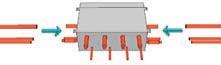
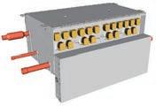
Space saving
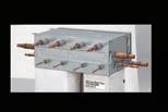
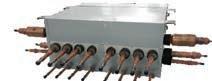
The 8 and 12 branch RB units allow for greater flexibility with refrigerant piping work for various floor layouts and building structures.


Separation tube Previous set up (3 x 4-Port RB Units example)
SET UP (12-Port RB Unit example)
When multiple outdoor units are connected, a sophisticated operation is performed by each compressor. Rather than running one compressor at full load and distributing refrigerant to one heat exchanger, this control method operates all compressors at part load and distributes refrigerant to all of the heat exchangers allowing for the overall system efficiency to be improved.
The heat exchanger in the outdoor unit is split into two parts (Top and Bottom). The efficiency of the heat exchanger has been improved by adopting an optimum refrigerant path control where the refrigerant is distributed more into the top heat exchanger as this is where there is a greater air flow intake.
Flexible refrigerant pipe work is possible through the use of various piping and RB Unit connections to match the floor layout and building structure.


(Multi-split type)


• The RB unit can be freely positioned between the first branch and the indoor unit.
• The maximum height difference between RB units is 15 m.
*2 RB Unit is not necessary for cooling only use Capacity limitations apply. See technical manual
Flexible installation of RB unit
Small & slim design saves space. Height 198 mm!
• Compact and slim design saves space
• Drain pipe not required
• The control box position can be changed to meet installation conditions
Installation is
from
•2-way connection
•Up to 2 multi-split type
RB units can be connected in series

Easy maintenance in narrow spaces
Maintenance can be performed from the side
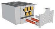
Sliding down the panel on the electrics box allows easy repair and maintenance
Parts can be replaced easily even within narrow ceiling spaces
• Combinations other than those specified are not supported.
Space saving combinations
AJT252GALCH AJT270GALCH
AJT324GALCH UNIT: AJT144 / 108GALCH UNIT: AJT144 / 126GALCH UNIT: AJT144 / 144GALCHUNIT: AJT108 / 108 / 090GALCHUNIT: AJT108 / 108 / 108GALCH
AJT342GALCH AJT360GALCH AJT378GALCH AJT396GALCH AJT414GALCH UNIT: AJT126 / 108 / 108GALCHUNIT: AJT144 / 108 / 108GALCHUNIT: AJT144 / 126 / 108GALCHUNIT: AJT144 / 144 / 108GALCHUNIT: AJT144 / 144 / 126GALCH
135.0kW (48HP)
AJT432GALCH UNIT: AJT144 / 144 / 144GALCH
efficiency combinations
44.8kW (16HP)
(22HP)
(24HP)
(26HP)
(28HP)
AJT144GALCHH AJT198GALCHH AJT216GALCHH AJT234GALCHH AJT252GALCHH UNIT: AJT072 / 072GALCH UNIT: AJT126 / 072GALCHUNIT: AJT072 / 072 / 072GALCHUNIT: AJT090 / 072 / 072GALCHUNIT: AJT108 / 072 / 072GALCH
(30HP)
(38HP) AJT270GALCHH AJT288GALCHH AJT306GALCHH AJT324GALCHH AJT342GALCHH UNIT: AJT126 / 072 / 072GALCHUNIT: AJT144 / 072 / 072GALCHUNIT: AJT126 / 108 / 072GALCHUNIT: AJT126 / 126 / 072GALCHUNIT: AJT144 / 126 / 072GALCH
(40HP)
(42HP)
(44HP)
AJT360GALCHH AJT378GALCHH AJT396GALCHH UNIT: AJT126 / 126 / 072GALCHUNIT: AJT126 / 126 / 126GALCHUNIT: AJT144 / 126 / 126GALCH
10HP : AJT090GALCH
12HP : AJT108GALCH
14HP : AJT126GALCH
16HP : AJT144GALCH
Note: Specifications are based on the following conditions:
Cooling: Indoor temperature of 27°CDB / 19°CWB, and outdoor temperature of 35°CDB / 24°CWB.
Heating: Indoor temperature of 20°CDB / (15°CWB), and outdoor temperature of 7°CDB / 6°CWB.
Pipe length: 7.5m; height difference between outdoor unit and indoor unit: 0m.
*1: Minimum connectible indoor unit number is 2.
*2: These are the measured values in the manufacturer’s anechoic chamber.
Because of the surrounding sound environment, the sound levels measured in actual installation conditions might be higher than the specified values here.
17 types and 112 models available to meet the requirements of almost any building design.

The AIRSTAGE™ indoor units were developed to be highly efficient, compact, low noise producing with user friendly operation.
With a variety of indoor units and capacities available, Fujitsu General has a unit that’s easy to install and maintain and matches almost any requirement.
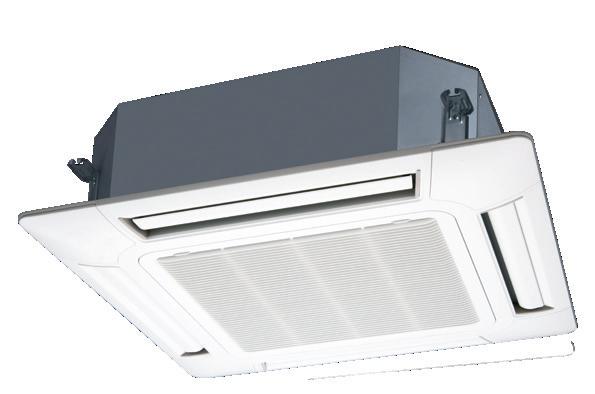
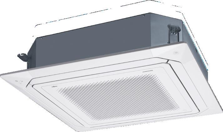
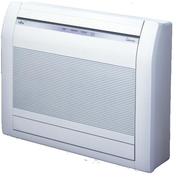
Cassette (1-way Flow type)
4-way Flow Compact Cassette
4-way Flow Cassette
Circular Flow Cassette
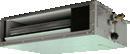
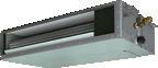
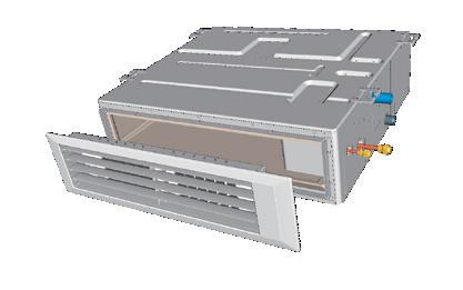
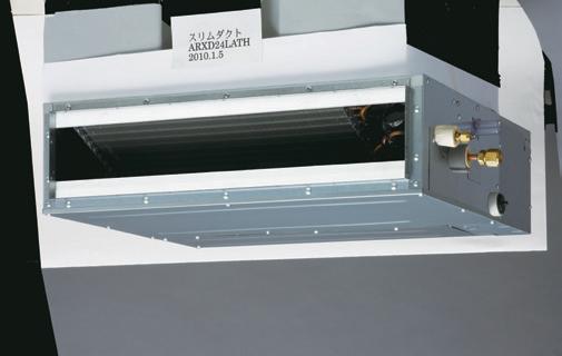
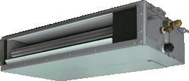
Mini Duct
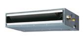
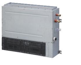
Slim Duct / Slim Concealed Floor
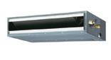
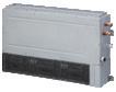
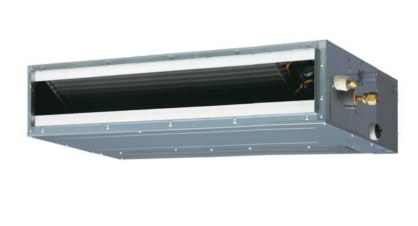
Medium Static Pressure Duct
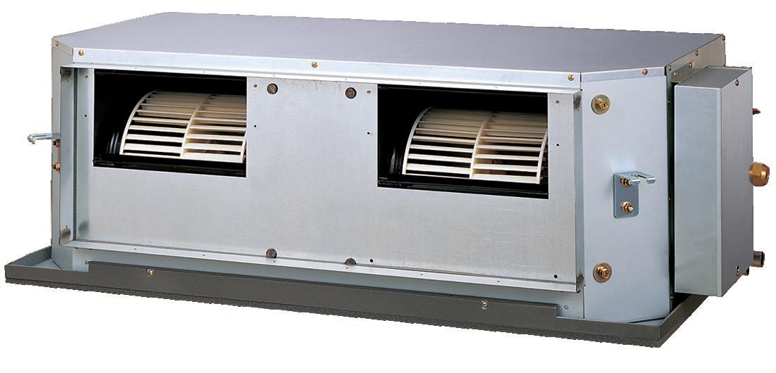
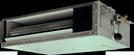
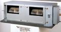
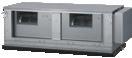
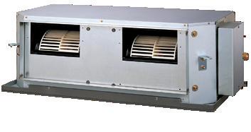
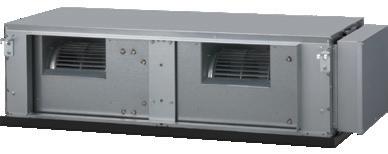
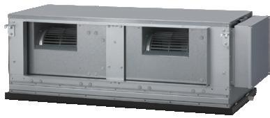
High Static Pressure Duct
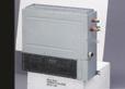
Floor (compact)
Floor / Ceiling
Ceiling
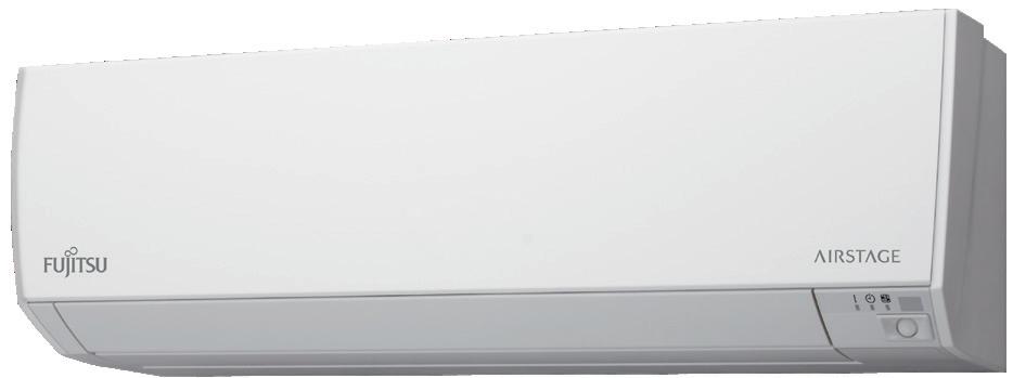
Wall Mounted (EEV Internal / External)
Comprehensive range of indoor units with various design and capacity ranges to suit most air conditioning needs. 17 types and 112 models, with a capacity range from 2.2kW to 28.0kW.
1-way Flow
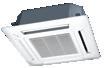
4-way Flow Compact AUXB007GLEH AUXB009GLEH AUXB012GLEH
4-way Flow (Slim type)
(Large type)
Circular Flow (Slim type)
(Large type)
Mini Duct (With drain pump)
Slim Duct (With drain pump)
Duct
Medium Static Pressure Duct
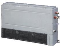
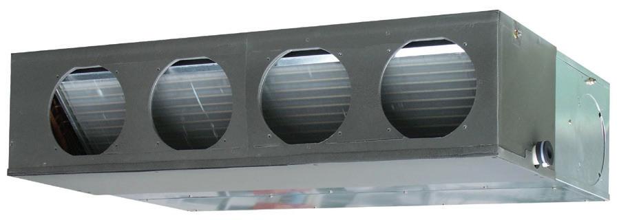
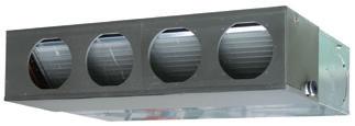
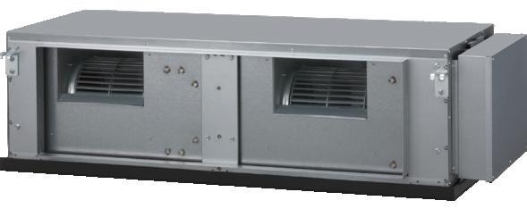
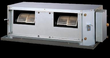
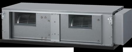
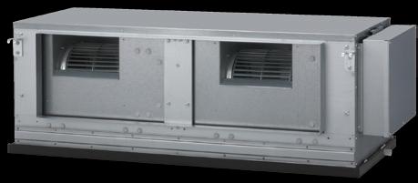
High Static Pressure Duct
Floor (Same as Ceiling models)
Slim Concealed Floor (Same as Slim Duct models)
Floor
Floor (compact)
Floor (compact) (EEV external)

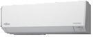
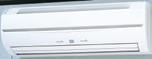
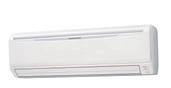
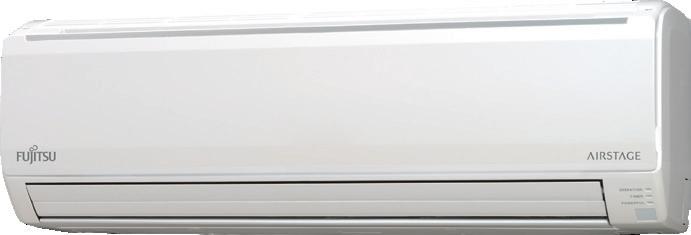
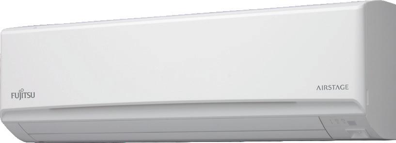
Wall Mounted (EEV external)


AUXV024GLEH
AUXB024GLEH
AUXD24GALH
AUXA24GALH* 1 AUXA30GALH AUXA34GALH AUXA36GALH AUXA45GALH
AUXM024GLEH AUXM024GLAH AUXM030GLEH AUXM030GLAH
AUXK024GLEH AUXK024GLAH AUXK030GLEH AUXK030GLAH

ARXK024GLGH
ARXD024GLEH
AUXK034GLEH AUXK034GLAH
AUXK036GLEH AUXK036GLAH
AUXA54GALH
AUXK045GLEH AUXK045GLAH
AUXK054GLEH AUXK054GLAH
ARXA024GLEH ARXA030GLEH ARXA036GLEH ARXA045GLEH ARXC036GTEH ARXC045GTEH ARXC060GTEH*2 ARXC072GTEH*2 ARXC090GTEH*2 ARXC096GTEH*2

ABYA024GTEH
ARXD024GLEH
Models (Slim type)
AUXV007GLEH / AUXV009GLEH / AUXV012GLEH
AUXV014GLEH / AUXV018GLEH / AUXV024GLEH

Features
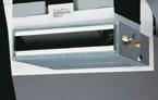
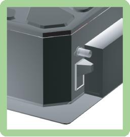
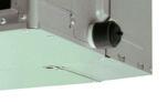
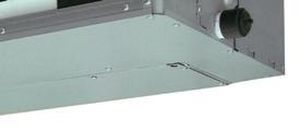
Their compact sizes make it easy to install them in a variety of commercial locations and environments.
• The chassis is less than 200 mm high in every model.
• All 7 to 12kBtu models are less than 1,000 mm wide.
• The chassis depth is 570 mm, which fits nicely into a grid-type ceiling.
Dimensions (Panel size) (Unit : mm)
7 9 12 14 18 24
(43)
(950)
(620)
(43)
(620)
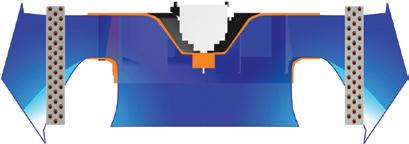
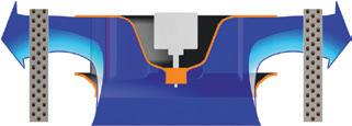
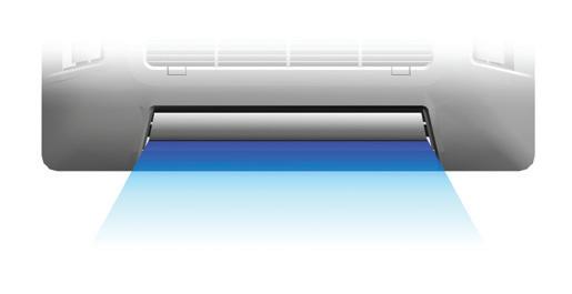
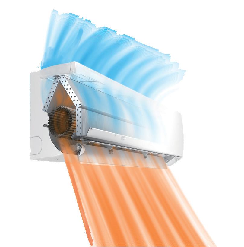
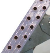
The large flap with triangularly arrayed louvers has a wider moveable range and directs airflow to the furthest corners of the room.

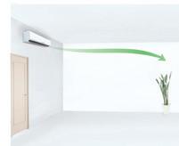
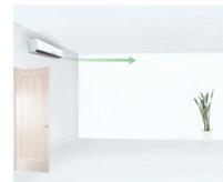
In cooling mode, the horizontal airflow reaches the furthest corners of the room and avoids hitting human bodies directly in order to provide comfortable air conditioning.
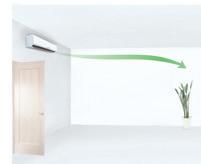
In heating mode, the warm air is directed downward toward the floor to warm the occupants' feet and lower bodies while keeping their heads relatively cool.

Compact depth fits the grid ceiling
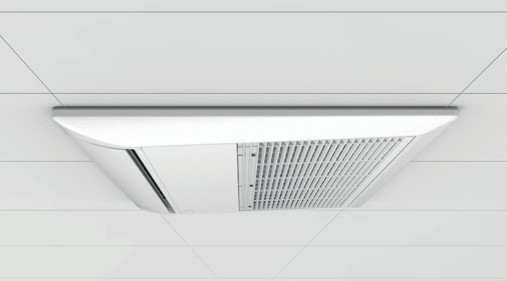
They produce little noise during operation, which makes them an ideal choice for use in hotel rooms.
By using new L-type piping kit, more flexible installation is possible.
Built-in drain pump as standard accessory, which enable to have maximum 700m piping height difference from the ceiling.

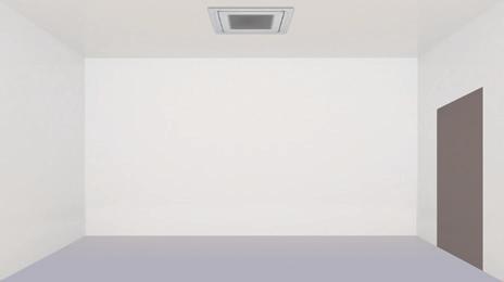
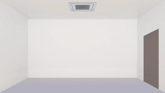
Note: This is a conceptual drawing. Air conditioning performance may vary depending on installation, room size, and the distance from the wall.
Optional parts
IR Receiver Unit: UTY-TRHX
Cassette Grille: UTG-UNYA-W / UTG-UNYB-W
External Power Supply Unit: UTZ-GXXC

Specifications
Drain hose diameter (I.D./O.D.)
Cassette grille
Note : Specifications are based on the following conditions.
Cooling : Indoor temperature of 27˚CDB / 19˚CWB, and outdoor temperature of 35˚CDB / 24˚CWB.
Heating : Indoor temperature of 20˚CDB / (15˚CWB), and outdoor temperature of 7˚CDB /
Dimensions (Unit: mm)
Models (Slim type)
AUXB007GLEH / AUXB009GLEH / AUXB012GLEH
AUXB014GLEH / AUXB018GLEH / AUXB024GLEH
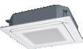
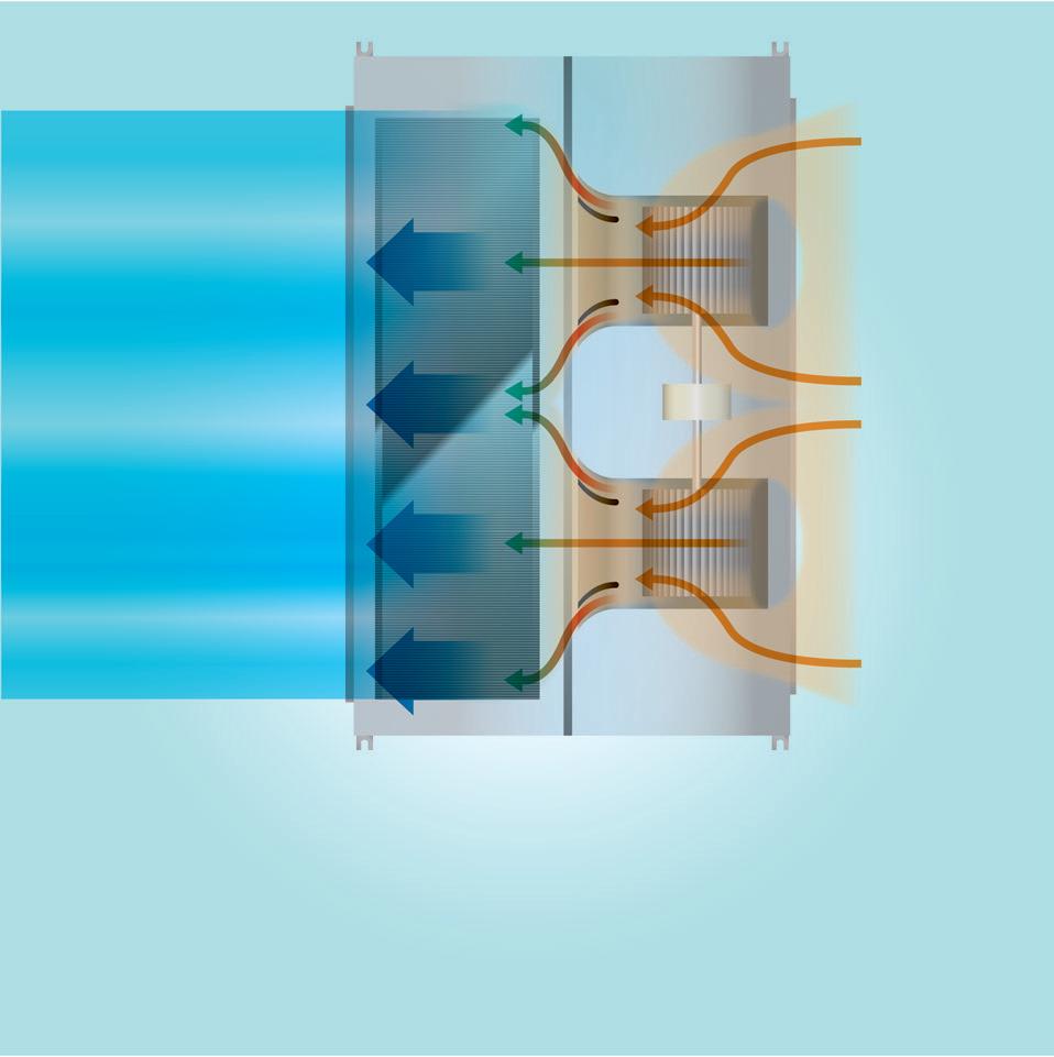
High efficiency design through 2-stage structure
Air distribution is evenly spread across the heat exchanger due to the new 2-stage turbo fan which produces two separate airflow streams.
Optimised wing form (laminar wing type) and wing number (7 blades each)
Designed by CFD-analysis (fluid) simulations
The compact cassette can be installed up to a height of 3.0m (12 / 14 / 18 / 24). Features
1 Maintenance of fan motor and
Maintenance of the fan motor and fan can be done easily after taking off the panel as the bell mouth of the fan can be removed easily.
3 Adaptation of transparent drainage parts
During installation, maintenance and operation, the drain pump and kit can be checked easily.
The world’s first 24,000Btu model in the compact cassette category.
(Easily installed by taking off ceiling panel of 600 x 600 size)

Optional parts
Air outlet shutter plate: UTR-YDZB
Insulation kit for high humidity: UTZ-KXGC
Fresh air intake kit: UTZ-VXAA
External power supply unit: UTZ-GXXC
Cassette Grille: UTG-UFYC-W
Specifications
Cassette grille
Note: Specifications are based on the following conditions:
Cooling: Indoor temperature of 27˚CDB / 19˚CWB, and outdoor temperature of 35˚CDB / 24˚CWB.
Heating: Indoor temperature of 20˚CDB / (15˚CWB), and outdoor temperature of 7˚CDB / 6˚CWB.
Pipe length: 7.5m; height difference between outdoor unit and indoor unit: 0m. Voltage: 230V.
Dimensions (Unit: mm)
Models (Slim type)
AUXD18GALH / AUXD24GALH
Models (Large type)
AUXA18GALH / AUXA24GALH / AUXA30GALH
AUXA34GALH / AUXA36GALH / AUXA45GALH
AUXA54GALH

Features
High efficiency airflow distribution has been achieved by the introduction of a 3 dimensional blade which increases the air passing over the heat exchanger.
The unique design of the louvres and added space between the chassis and ceiling maximises airflow distribution within the room.
Adjustment of hanger position is possible after installation
Specifications
Cassette grille
Note: Specifications are based on the following conditions:
Cooling: Indoor temperature of 27˚CDB / 19˚CWB, and outdoor temperature of 35˚CDB / 24˚CWB.
Heating: Indoor temperature of 20˚CDB / (15˚CWB), and outdoor temperature of 7˚CDB / 6˚CWB.
Pipe length: 7.5m; height difference between outdoor unit and indoor unit: 0m. Voltage: 230V.
Dimensions (Unit: mm) AUXD18 / AUXD24
Optional parts
IR receiver unit: UTY-LRHYB1
Cassette grille: UTG-UGYA-W
*1: This value is “Cooling operation/Heating operation”
Models
AUXN009GLAH / AUXN012GLAH / AUXN014GLAH
AUXM018GLEH / AUXM024GLEH / AUXM030GLEH
AUXM018GLAH / AUXM024GLAH / AUXM030GLAH
Features
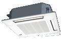
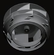
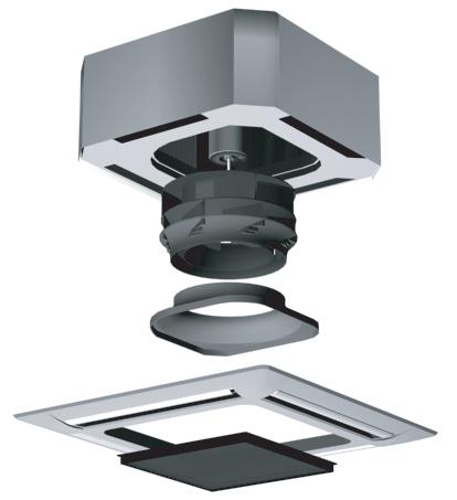
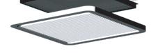
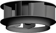
The new cassette type creates a consistent and even temperature via multi-directional 360° airflow functionality. This is achieved by mounting a high performance DC fan motor, new turbo fan and unique seamless airflow louvre design.
Achieve a consistent and even temperature in the room with circular flow and wide vertical airflow spreading conditioned air to every corner of the room.
Each louvre can be set individually with the touch panel wired remote control, allowing different directional airflows according to various room layouts.
* Touch Panel Wired RC (UTY-RNRYT5) and Central remote controller (UTYDCGYZ3) only


Comfortable air conditioning by preventing direct blowing of cold air and by providing swinging airflow simultaneously. Efficient air conditioning based on the room layout

Energy saving operation starts automatically by detecting the motion of a person.
The human sensor detects movement and activates or deactivates energy saving mode accordingly.
Two modes can be selected: save operation and stop mode.
* Touch Panel Wired RC (UTY-RNRYT5) and Central remote controller(UTY-DCGYZ3) only
Optional parts
IR receiver unit: UTY-LBHXD
Human sensor kit: UTY-SHZXC
Air outlet shutter plate: UTR-YDZK
Panel spacer: UTG-BKXA-W
Wide panel: UTG-AKXA-W
Insulation kit for high humidity: UTZ-KXRA
Fresh air intake kit: UTZ-VXRA
External power supply unit: UTZ-GXXC (AUXM ***GLEH)
Cassette grille: UTG-UKYC-W

Specifications
Cassette grille
Note: Specifications are based on the following conditions:
Cooling: Indoor temperature of 27˚CDB / 19˚CWB, and outdoor temperature of 35˚CDB / 24˚CWB.
Heating: Indoor temperature of 20˚CDB / (15˚CWB), and outdoor temperature of 7˚CDB / 6˚CWB.
Pipe length: 7.5m; height difference between outdoor unit and indoor unit: 0m. Voltage: 230V. When AUXM018GLAH, GLEH is connected to the outdoor unit other than J-IVL, pipe diameter should be Ø9.52 / Ø15.88 (Liq / Gas)
Dimensions (Unit: mm)
Models
AUXK018GLEH / AUXK024GLEH / AUXK030GLEH
AUXK034GLEH / AUXK036GLEH / AUXK045GLEH
AUXK054GLEH
AUXK018GLAH / AUXK024GLAH / AUXK030GLAH
AUXK034GLAH / AUXK036GLAH / AUXK045GLAH
AUXK054GLAH
Features
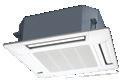
The new cassette type creates a consistent and even temperature via multi-directional 360° airflow functionality. This is achieved by mounting a high performance DC fan motor, new turbo fan and unique seamless airflow louvre design.
Achieve a consistent and even temperature in the room with circular flow and wide vertical airflow spreading conditioned air to every corner of the room.
New DC fan motor
Highly efficient turbo fan
Seamless airflow louvre
Each louvre can be set individually with the touch panel wired remote control, allowing different directional airflows according to various room layouts.
* Touch Panel Wired RC (UTY-RNRYT5) and Central remote controller (UTYDCGYZ3) only
Comfortable air conditioning by preventing direct blowing of cold air and by providing swinging airflow simultaneously.
Energy saving operation starts automatically by detecting the motion of a person. The human sensor detects movement and activates or deactivates energy saving mode accordingly.
Two modes can be selected: save operation and stop mode.
* Touch Panel Wired RC (UTY-RNRYT5) and Central remote controller (UTY-DCGYZ3) only
Optional parts
IR receiver unit: UTY-LBHXD
Human sensor kit: UTY-SHZXC
Efficient air conditioning based on the room layout
Air outlet shutter plate: UTR-YDZK
Panel spacer: UTG-BKXA-W
Wide panel: UTG-AKXA-W
Insulation kit for high humidity: UTZ-KXRA
Fresh air intake kit: UTZ-VXRA
External power supply unit: UTZ-GXXC (AUXK***GLEH)
Cassette grille: UTG-UKYC-W
Specifications
Cassette grille
Note: Specifications are based on the following conditions:
Cooling: Indoor temperature of 27˚CDB / 19˚CWB, and outdoor temperature of 35˚CDB / 24˚CWB.
Heating: Indoor temperature of 20˚CDB / (15˚CWB), and outdoor temperature of 7˚CDB / 6˚CWB.
Pipe length: 7.5m; height difference between outdoor unit and indoor unit: 0m. Voltage: 230V.
Dimensions (Unit: mm)
When AUXK018GLAH, GLEH is connected to the outdoor unit other than J-IVL, pipe diameter should be Ø9.52 / Ø15.88 (Liq / Gas) When AUXK036GLAH, GLEH, AUXK045GLAH, GLEH, and AUXK054GLAH, GLEH are connected to the outdoor unit other than J-IVL, gas pipe diameter should be Ø19.05.
Models (with drain pump)
ARXK007GLGH / ARXK009GLGH / ARXK012GLGH
ARXK014GLGH / ARXK018GLGH / ARXK024GLGH
Features
• The compact design allows for the installation space to be reduced down to a minimum depth of 450mm and height of 198mm
• Lightweight: 16kg, 10% down
Low noise is realised drastically with the stabilised airflow design

By using the DC fan motor, it is possible to change the static pressure range from 0 to 50 Pa*. The change of static pressure range is possible by the remote controller.
* 0 to 30 Pa. (007, 009 and 012 model)
can be replaced from the side of the body where

Multi-step airflow speed control allows this model to be installed in quiet areas.
• Thin design provides a comfortable living environment over a wide area
Specifications
* Compatible remote controllers:
Specifications
Note: Specifications are subject to the following conditions:
Cooling: Indoor temperature of 27°CDB/19°CWB, and outdoor temperature of 35°CDB/24°CWB. Heating: Indoor temperature of 20˚CDB/(15˚CWB), and outdoor temperature of 7˚CDB/6˚CWB.
Pipe length: 7.5 m; Height difference between outdoor unit and indoor unit: 0 m. Voltage: 230 [V].
Optional parts
Remote sensor unit:
IR receiver unit: Silver Ion Filter:
*For more details, please refer to the chapter “Optional parts”.
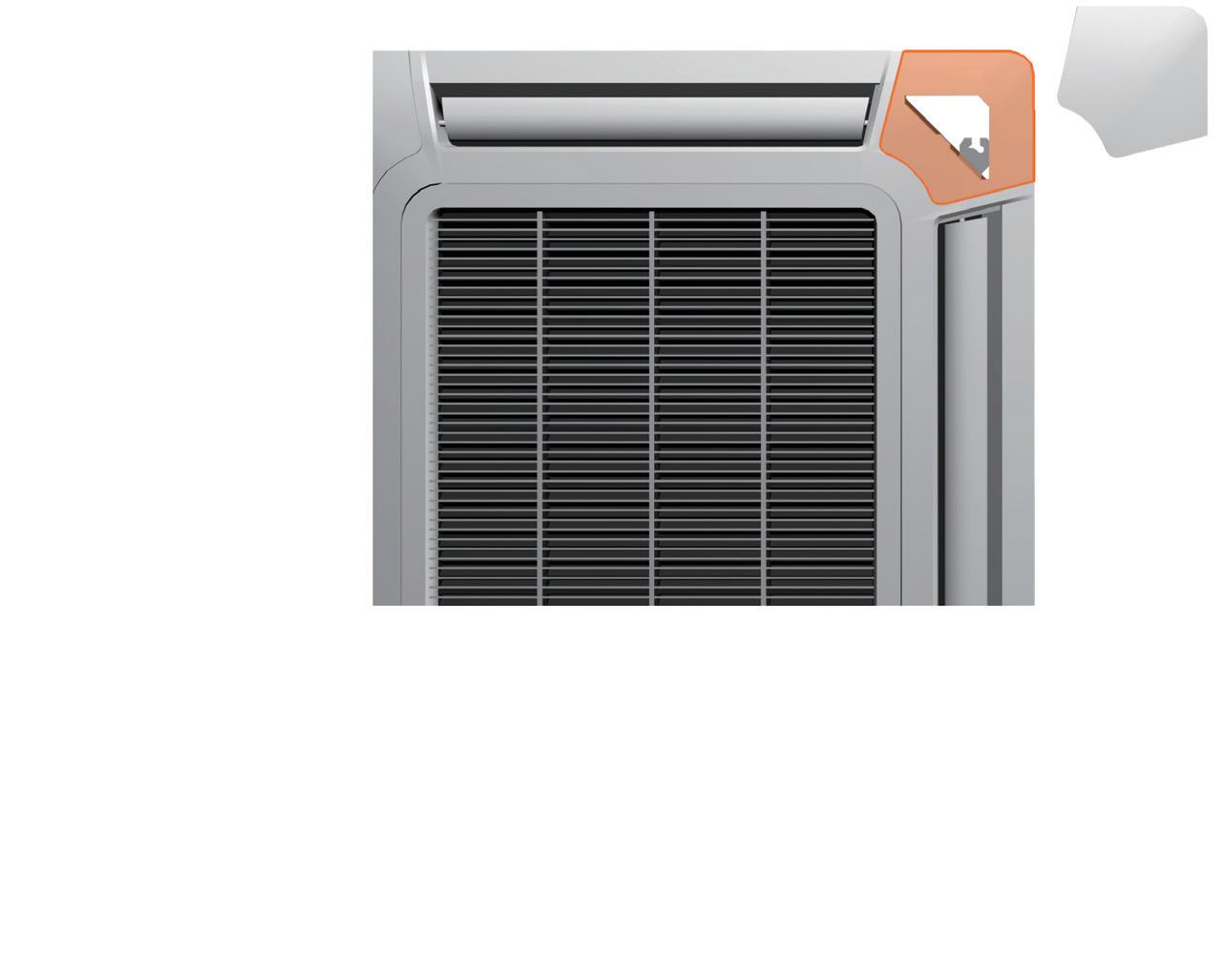
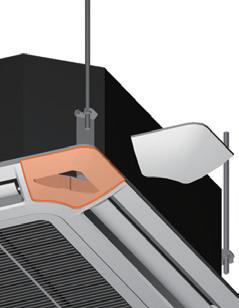
• Automatic louvre grille provides comfortable air conditioning from floor to ceiling (option)
Optional parts
Remote sensor unit: UTY-XSZXZ1
IR receiver unit: UTY-TRHX
Auto louvre grille kit: UTD-GXTA-W (for ARXK007/009/012/014) UTD-GXTB-W (for ARXK018) UTD-GXTC-W (for ARXK024)
External power supply unit: UTZ-GXXC
UTY-XSZXZ1
UTY-TRHX
UTD-HFTA (004-014)
External power supply unit:
Auto Louver Grille Kit:
Note: Specifications are based on the following conditions:
UTD-HFTB (018)
UTZ-GXXA, UTZ-GXXC*
UTD-GXTA-W (004-014)
UTD-GXTB-W (018)
UTD-GXTC-W (024)
Cooling: Indoor temperature of 27˚CDB / 19˚CWB, and outdoor temperature of 35˚CDB / 24˚CWB.
UTD-HFTC (024)
WLAN adapter:
FG-AC-WIF1Z1
Heating: Indoor temperature of 20˚CDB / (15˚CWB), and outdoor temperature of 7˚CDB / 6˚CWB.
UTY-TFSXJ3, UTY-TFSXZ1 (007-024)
Pipe length: 7.5m; height difference between outdoor unit and indoor unit: 0m. Voltage: 230V.
Dimensions (Unit: mm)
Dimensions
Auto Louver Grille Kit (Optional)
The slim design of the unit provides comfortable cooling and heating air conditioning over a wide area.
The optional automatic louver grille, which fits nicely into any interior decor, provides comfortable air conditioning (Optional)
*The design of the service access depends on the installation method. Refer to the installation manual for more information.
ARXD007GLEH / ARXD009GLEH / ARXD012GLEH ARXD014GLEH / ARXD018GLEH / ARXD024GLEH
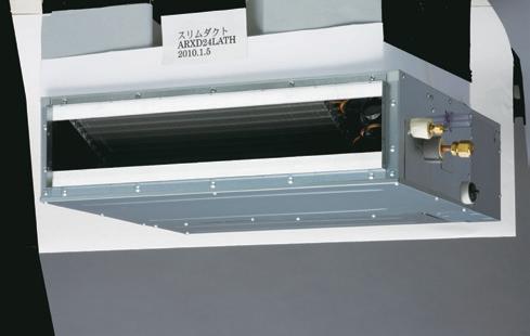
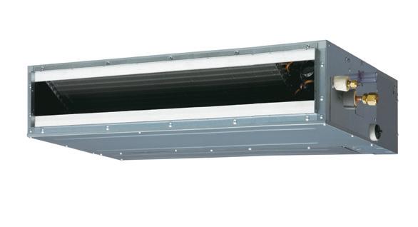
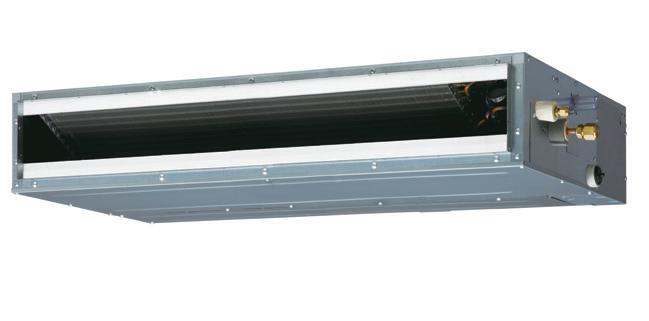

Features
With a slim design, this indoor unit can be installed in narrow ceiling spaces.
By using DC fan motor, it is possible to change the static pressure range from 0 to 90Pa. The static pressure range is configurable through the remote controller.
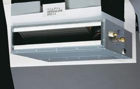
Simple flat auto louvre will provide comfortable airflow and complement luxury interiors.
Optional parts
Specifications
Note: Specifications are subject to the following conditions:
Cooling: Indoor temperature of 27°CDB/19°CWB, and outdoor temperature of 35°CDB/24°CWB.
Heating: Indoor temperature of 20˚CDB/(15˚CWB), and outdoor temperature of 7˚CDB/6˚CWB.
Pipe length: 7.5 m; Height difference between outdoor unit and indoor unit: 0 m. Voltage: 230 [V].
*1: This value is under cooling operation.
*: ARXD04GALH cannot be connected to J-IVS/J-IV/J-IVL/VR-IV Series.
Optional parts
Note: Specifications are based on the following conditions:
UTY-XSZXZ1
UTB-YWC (04)
UTZ-GXXA, UTZ-GXXC*
Cooling: Indoor temperature of 27˚CDB / 19˚CWB, and outdoor temperature of 35˚CDB / 24˚CWB.
Heating: Indoor temperature of 20˚CDB / (15˚CWB), and outdoor temperature of 7˚CDB / 6˚CWB.
UTY-TRHX (007-024)
UTY-TFSXJ3 (007-024)
UTY-TFSXZ1 (007-024)
FG-RC-WIF1Z2 (04)
FG-AC-WIF1Z1 (007-024)
Dimensions (Unit: mm)
Remote sensor unit: IR receiver unit: Auto louvre grille kit: (for ARXD007/009/012/014)
External power supply unit:

*For more details, please refer to the chapter “Optional parts”.
UTD-GXTA-W (04, 007-014)
UTD-GXTB-W (018)
Pipe length: 7.5m; height difference between outdoor unit and indoor unit: 0m. Voltage: 230V.
UTD-GXTC-W (024)
UTD-HFTA (04, 007-014)
UTD-HFTB (018)
UTD-HFTC (024)
*Service accessibility must be allowed for when installing the product. Please consult the installation manual for the necessary service access size.
ARXD04GALH ARXD 007-014GLEH 574 a P200×2=400 b 734 c
Models
ARXA024GLEH / ARXA030GLEH
ARXA036GLEH / ARXA045GLEH
Features
In the case of bottom return air connection, not only does the indoor unit design allow for installation in a narrow ceiling space of up to 270mm, further space savings have been achieved by mounting the electrical control box internally inside the chassis.
Improved motor efficiency compared to the previous model.
This unit can be installed in a range of locations such as high rise apartments through low static pressure design.
It can also be installed in open spaces when higher static pressure is required, such as offices.
It is possible to change the static pressure range from 0 to 140Pa (024 and 030 models).
See below for the case of rear suction type
Structural improvement is attained by making the bottom panel two pieces, front and rear. The internal fan casing is also manufactured in two pieces, namely upper and lower. The maintenance of the motor and fan can be easily carried out by removing the rear panel and the lower part of the casing while leaving the main chassis installed.
Changing the static pressure range is possible with the remote controller
Specifications
Note: Specifications are based on the following conditions:
Cooling: Indoor temperature of 27˚CDB / 19˚CWB, and outdoor temperature of 35˚CDB / 24˚CWB.
Heating: Indoor temperature of 20˚CDB / (15˚CWB), and outdoor temperature of 7˚CDB / 6˚CWB.
Pipe length: 7.5m; height difference between outdoor unit and indoor unit: 0m. Voltage: 230V.
Dimensions (Unit: mm)
*Service accessibility must be allowed for when installing the product. Please consult the installation manual for the necessary service access size.
Optional parts
Remote sensor unit: UTY-XSZXZ1
Long life filter: UTD-LF25NA
Flange (square): UTD-SF045T
External power supply unit: UTZ-GXXC
Flange (round): UTD-RF204
IR receiver unit: UTY-TRHX
Drain pump unit: UTZ-PX1NBA
Models
ARXC036GTEH / ARXC045GTEH / ARXC060GTEH
ARXC072GTEH / ARXC090GTEH
ARXC096GTEH

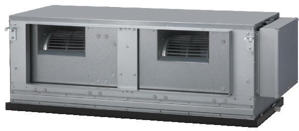
Features
It is possible to change the static pressure range from 0 to 200Pa (036GTEH ) / 300Pa (072 / 090 / 096GTEH). 045 / 060 GTEH models do not have static pressure adjustment.
Models: 036 / 045 / 060GTEH
Cutting off the corners of the conventional indoor unit front panel and fan casing has enabled less turbulent airflow.
Low noise is realised by adopting a plastic case and a plastic fan.
Improved motor efficiency from previous model.
ARXC036GTEH : Plastic fan [42dB(A)]
* Model: material
(At 100Pa: actual noise measurement value)
A compact size and lightweight indoor unit has been developed by reducing the basic chassis and the overall material weight.
Optional parts
Long-life filter: UTD-LF60KA (For ARXC036/045/060)
IR receiver unit: UTY-TRHX
Remote sensor unit: UTY-XSZXZ1
External power supply unit: UTZ-GXXC
Specifications
Drain hose diameter (I.D./O.D.)
Note: Specifications are based on the following conditions:
Cooling: Indoor temperature of 27˚CDB / 19˚CWB, and outdoor temperature of 35˚CDB / 24˚CWB.
Heating: Indoor temperature of 20˚CDB / (15˚CWB), and outdoor temperature of 7˚CDB / 6˚CWB.
Pipe length: 7.5m; height difference between outdoor unit and indoor unit: 0m. Voltage: 230V.
Dimensions (Unit: mm)
Models: ARXC036 / ARXC045 / ARXC060
Models: ARXC072 / ARXC090 / ARXC096
* ARXC060 / 072 / 090 / 096G cannot be connected to J-IV or J-IVS Series.
Models (EEV internal)
AGYA007GCGH / AGYA009GCGH
AGYA012GCGH / AGYA014GCGH
Models (EEV external)
AGYE007GCEH / AGYE009GCEH
AGYE012GCEH / AGYE014GCEH
Features
Individual vertical airflow by 2 fans can control the whole room comfortably.
Quiet operation is realised by 6 fan speed control. (via 2 wired controllers)
Due to compact and flexible methods for installation including floor, concealed, half concealed, or wall mounted, installation approach can be modified to match the room layout.
Drain hose and piping can be drawn flexibly in the right, left, sideways, and down directions.
Specifications
Note: Specifications are based on the following conditions:
Cooling: Indoor temperature of 27°CDB / 19°CWB, and outdoor temperature of 35°CDB / 24°CWB.
When AGY*007 and AGY*009 are connected to the outdoor unit other than J-IVL, gas pipe diameter should be Ø12.70.
Heating: Indoor temperature of 20°CDB / (15°CWB), and outdoor temperature of 7°CDB / 6°CWB.
Pipe length: 7.5m; height difference between outdoor unit and indoor unit: 0m. Voltage: 230V.
Dimensions (Unit: mm)
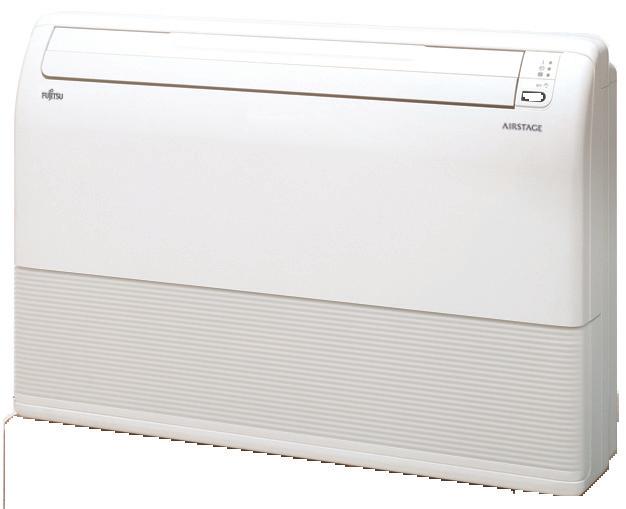
Models
ABYA012GTEH / ABYA014GTEH
ABYA018GTEH / ABYA024GTEH
Features
Example for floor installation
Floor console
auto
A combination of up / down and right / left directional swing allows three dimensional air direction control.
Example for ceiling installation
Under ceiling

High power DC fan motor
High power
Wide rotation range
High efficiency
Symmetrical, slim and compact design.
Specifications
(Unit: mm)
When operation is stopped, the louvres will automatically close. (This function is available on all non-ducted models)
Super vane
Double Louvre super vane with newly developed special configuration boosts airflow sending cool air quickly to every corner of the room.
Optional parts
External power supply unit: UTZ-GXXC
Note: Specifications are based on the following conditions:
Cooling: Indoor temperature of 27˚CDB / 19˚CWB, and outdoor temperature of 35˚CDB / 24˚CWB.
Heating: Indoor temperature of 20˚CDB / (15˚CWB), and outdoor temperature of 7˚CDB / 6˚CWB.
Pipe length: 7.5m; height difference between outdoor unit and indoor unit: 0m. Voltage: 230V.
Dimensions (Unit: mm)
Models
ABYA030GTEH / ABYA036GTEH
ABYA045GTEH / ABYA054GTEH
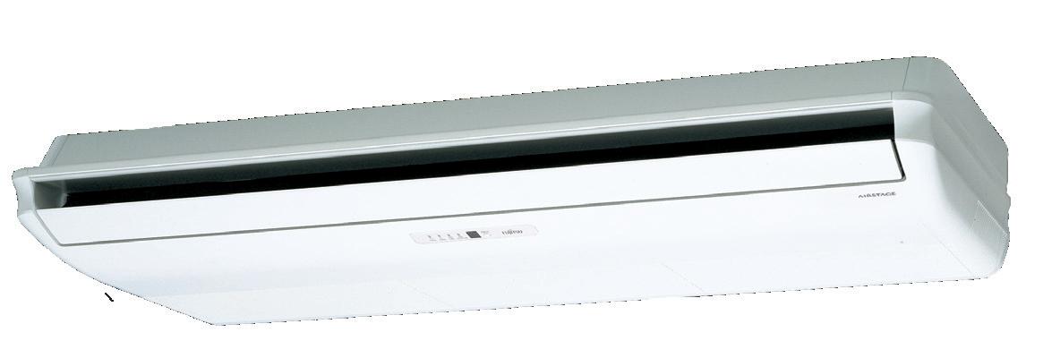
General installation pattern which suspends the indoor unit from the ceiling.
Auto airflow direction and auto swing
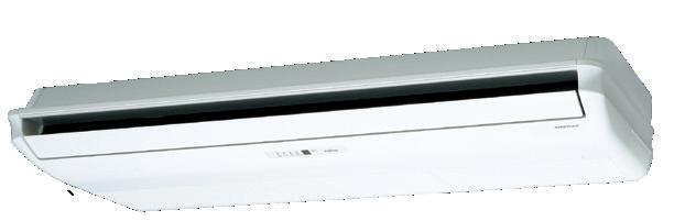
Installation pattern where part of the indoor unit is embedded into the ceiling.
Installation
is insufficient.
Long airflow ensures comfort to every corner of a large room.
• High power • Wide rotation range • High efficiency
Optional drain pump unit allows flexible installation design.
Specifications
Optional parts
Drain Pump Unit: UTR-DPB24T
Flange: UTD-RF204
External Power Supply Unit: UTZ-GXXC
Note: Specifications are based on the following conditions:
Cooling: Indoor temperature of 27˚CDB / 19˚CWB, and outdoor temperature of 35˚CDB / 24˚CWB.
Heating: Indoor temperature of 20˚CDB / (15˚CWB), and outdoor temperature of 7˚CDB / 6˚CWB.
Pipe length: 7.5m; height difference between outdoor unit and indoor unit: 0m. Voltage: 230V.
Dimensions (Unit: mm)
Models (EEV internal)
ASYA007GCGH / ASYA009GCGH / ASYA012GCGH
ASYA014GCGH
Models (EEV external)
ASYE007GCEH / ASYE009GCEH / ASYE012GCEH
ASYE014GCEH
Features
Highly efficient compact design is realised by mounting a high density and large heat exchanger.
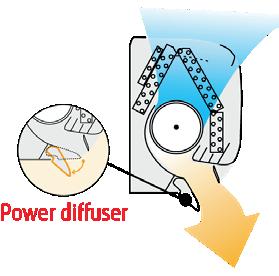
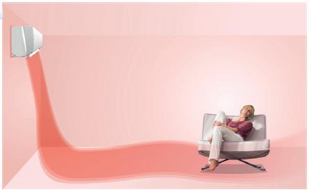
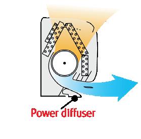
Comfortable air conditioning is provided by mounting our unique power diffuser.
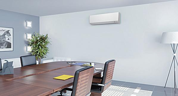
The compact body makes it possible to install discreetly even in a meeting room or office where comfortable air conditioning is provided.

Energy saving operation starts automatically by detecting the motion of a person in the space. Two modes of save operation mode and stop mode can be selected.
* If you want to use the Occupancy sensor control’ function, you need an operating device that can
the Occupancy
control’ function. For example: Wired RC (Touch panel).
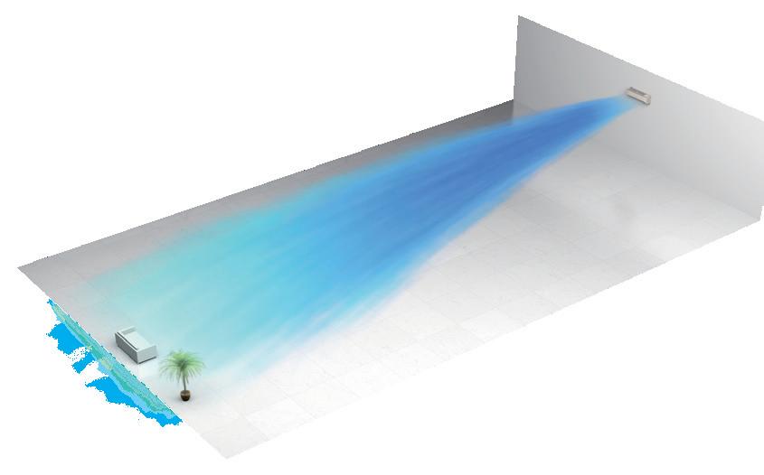
Heating Vertical airflow provides powerful floor level heating.
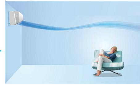
Multi-step airflow control is possible to suit the environment.
Specifications
Drain hose diameter (I.D./O.D.)
EV Kit (option)
Note: Specifications are based on the following conditions:
Cooling: Indoor temperature of 27°CDB / 19°CWB, and outdoor temperature of 35°CDB / 24°CWB.
Heating: Indoor temperature of 20°CDB / (15°CWB), and outdoor temperature of 7°CDB / 6°CWB.
Pipe length: 7.5m; height difference between outdoor unit and indoor unit: 0m. Voltage: 230V.
Dimensions (Unit: mm)
Models
ASYA18GBCH / ASYA24GBCH ASYA030GTEH / ASYA034GTEH
Powerful airflow (ASYA030GTEH)
The Occupancy sensor contributes to further energy savings (ASYA030 / 034GTEH only)
Energy saving operation starts automatically by detecting the motion of a person in the space. Two modes of save operation mode and stop mode can be selected.
* If you want to use the Occupancy sensor control’ function, you need an
For example: Wired RC (Touch panel).
Features Quiet operation and 6 fan speed control (ASYA030 / 034GTEH only)
Noise level is drastically reduced through the new airflow structure. Additionally, multi-step quiet operation is available by 6 step sound level settings.
Power diffuser (ASYA18 / 24GBCH)

Optional parts
External power supply unit: UTZ-GXXC
Specifications
Note: Specifications are based on the following conditions:
Cooling: Indoor temperature of 27°CDB / 19°CWB, and outdoor temperature of 35°CDB / 24°CWB.
Heating: Indoor temperature of 20°CDB / (15°CWB), and outdoor temperature of 7°CDB / 6°CWB.
Pipe length: 7.5m; height difference between outdoor unit and indoor unit: 0m. Voltage: 230V. When ASYA18GBCH is connected to the outdoor unit other than J-IVL, pipe diameter should be Ø9.52 / Ø15.88 (Liq / Gas).
Dimensions (Unit: mm)
Models: ASYA18 / ASYA24
Models: ASYA030 / ASYA034

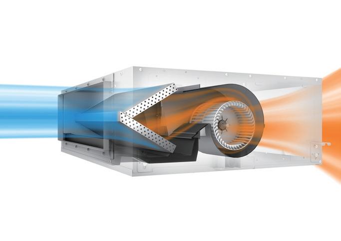
High efficiency and low noise levels are achieved by using a highly efficient heat exchange process. A comfortable air conditioned space is achieved by conveniently selecting whether to use the heat exchange or normal ventilation setting according to the requirements of the space.

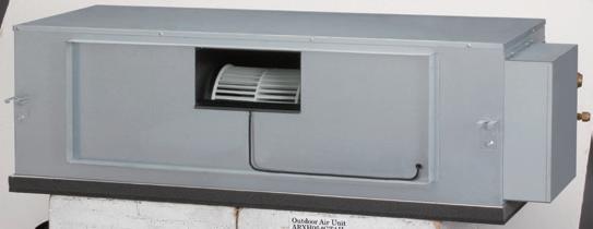
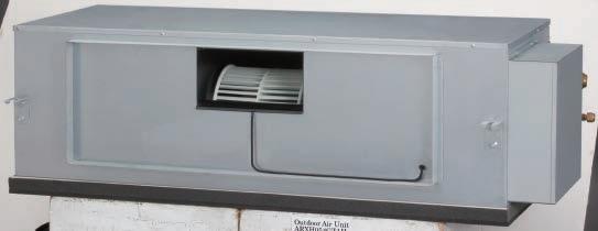
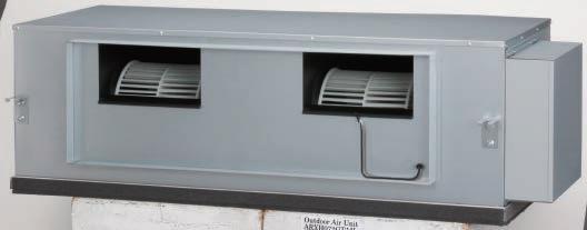
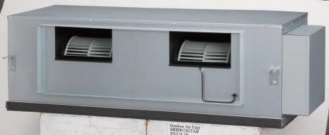
Outdoor-air Processing Unit
Models
ARXH054GTAH
ARXH072GTAH
ARXH096GTAH
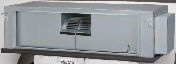
Features
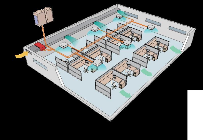
An Outdoor-air Processing Unit can be connected in the same VRF*1 System as the indoor units and can create fresh and comfortable air supply together using our highly advanced technology.
*1. Connectable VRF Series: J-IVS, J-IV, J-IVL, V-III and VR-IV OAU cannot be used where the ambient temperature is 40°C or higher.
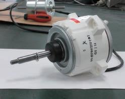
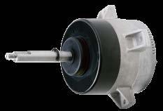
High energy savings and flexible duct design by using a DC motor
• Greatly reduces electricity consumption by adopting a permanent magnet compared to when using an AC motor
• Compared with an AC motor, changing the fan speed makes it possible to respond with flexibility to the external static pressure from 50 Pa to 240 Pa. Even when the damper equipment is not used, the static pressure can be adjusted and duct design is made easy
• Static pressure can be set easily using wired remote controller
• A lightweight compact design at just 425 mm in height and 55 kg in weight for ARXH072 type. This unit can be installed easily even within a narrow space.
A variety of optional controllers are available, such as individual controllers, central controllers and building management controllers.
Individual controllers
Specifications
Note: Specifications are based on the following conditions.
Cooling: Outdoor temperature of 33°CDB / 28°CWB.
Heating: Outdoor temperature of 0°CDB / -2.9°CWB.
Pipe length: 7.5m Voltage: 230 V.
Dimensions (Unit: mm)
ARXH054
ARXH072
Central controllers

ARXH096


The AIRSTAGE™ control system can control air conditioning of individual rooms, centralise control by floor or by building, or centralise energy saving air conditioning control for large buildings. A variety of air conditioning management options are available to match the requirements of the application, including integrating with the building control system, connecting with single split models and various interfaces.
CONTROL SYSTEM OVERVIEW
COMPARISON TABLE OF CONTROLLERS
INDIVIDUAL CONTROLLER
CENTRALISED CONTROLLER
CONVERTER / ADAPTOR
Fujitsu General provides a diverse range of flexible control solutions to suit a variety of applications.

Automatic control of A/C (schedule timer, weekly timer etc.)
Customise the level of control for staff and end users (RC prohibition, room temp set point limitation etc.)
Group control
Advanced energy saving (peak cut, indoor unit lead lag operation etc.)
Remote management
Manage multiple sites
Energy charge apportionments
Monitor energy consumption
Integrate FGL A/C into BMS


Centralised A/C


Advanced energy
(peak
Monitor energy consumption
Integrate FGL A/C into BMS
Local control for office staff
Automatic control of A/C (schedule timer, weekly timer etc.)
Centralised A/C control for management
Customise the level of control for office staff (RC prohibition, room temp set point limitation etc.)
Advanced energy saving (peak cut, indoor unit lead lag operation etc.)
Remote management
Energy charge apportionment
Monitor energy consumption
Integrate FGL A/C into BMS
Interlock with human sensor for meeting room

User’s needs are supported by offering a variety of controls, such as individual control, central control and building management control options.
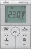
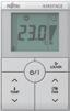
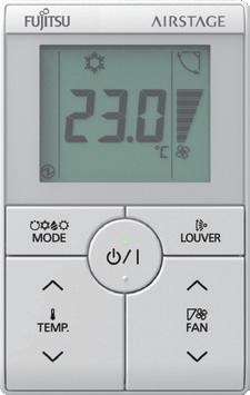
Wired Remote Controller
(touch panel)
UTY-RNRYT5


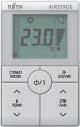
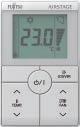
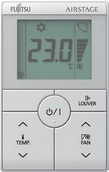
Simple Remote Controller
UTY-RSRY
UTY-RHRY Without operation mode
Wireless Remote Controller
UTY-LNHY For Cassette For Circular Flow Cassette
IR Receiver Unit
UTY-TRHX For Duct type
UTB-TWC For Duct type
IR Receiver Unit
UTY-LRHYB1 For Cassette type
UTY-LBHXD For Circular Flow Cassette
System Controller
UTY-APGXZ1
UTY-ALGXZ1 (Lite edition)

Touch Panel Controller
For external devices
BACnet Gateway
UTY-ABGXZ1
BACnet Gateway So
UTY-VBGX Hardware
Network Converter (BMS / LONWORKS)
UTY-VLGX

MODBUS Converter For VRF
UTY-VMGX
MODBUS Converter for indoor unit
UTY-VMSX
KNX® Convertor For VRF
UTY-VKGX
KNX® Convertor for indoor unit
UTY-VKSX
BMS, home automation system

*1. USB Adaptor: Echelon® U10 USB Network Interface
*2. BMS / BAS: Building Management System / Building Automation System or
Network Converter (DC


UTY-RVRY
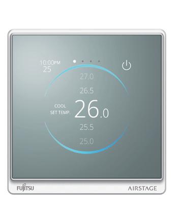
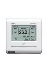
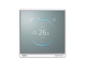
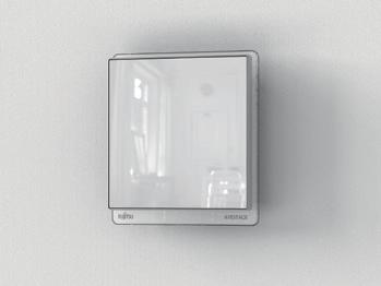
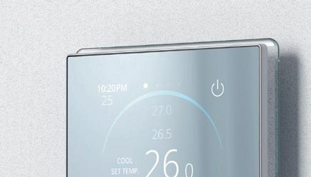
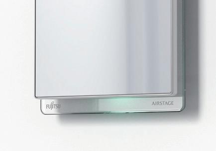
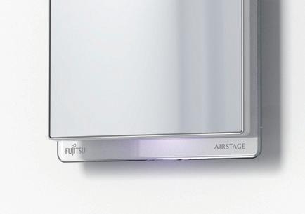
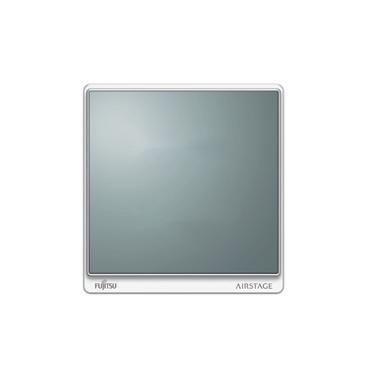
Kagami, the stylish new design controller, enables intuitive operation via touch screen. It is compatible with many 2-wired indoor units.
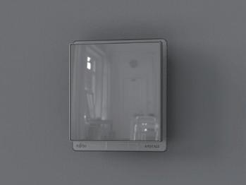
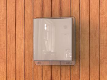
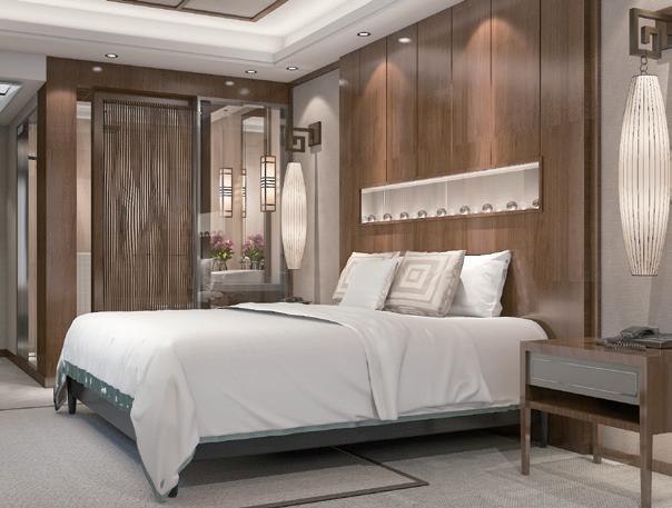
The mirrored glass design of Kagami allows the controller to blend seamlessly into any room’s décor.
The sleek and stylish design won the 2022 Good Design Award1 and was selected as a finalist for the 2023 IDEA Award.
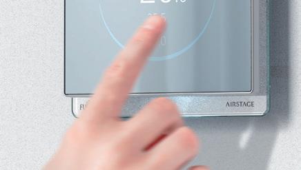
The intuitive touch screen can be operated by swiping vertically and horizontally, allowing complete control of the users comfort. Users can operate the controler without using manuals.


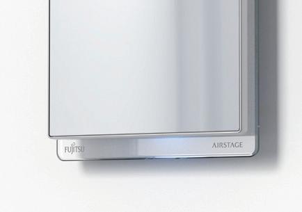
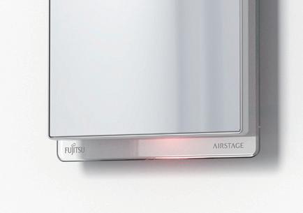
When not in use, the operation mode is indicated through LED lamp colours shown under the controller.
The LED lamp can be switched ON and OFF to avoid glare at night.


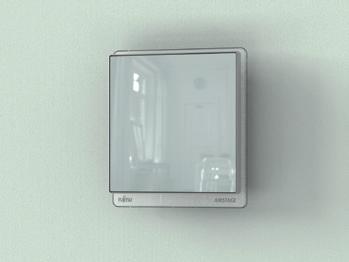


The controller can display hotel logos when not in use. Images are sent via Bluetooth® connection where data is saved in the flash memory built into each controller.
* Color display available
Set up your new Wired Remote Controller via Bluetooth from your smartphone (or directly from the controller)
Features:
• Initial configuration
• Function setting
• Custom logo import
• Copy settings between controllers


The initial controller settings and indoor unit function settings can be sent from a smartphone by pairing with the controller via Bluetooth. It also can read the setting values of a paired controller, and send a copy of them to one or more additional controllers, significantly reducing installation time.
Specifications
Model name
Power supply
Dimensions (H x W x D) mm
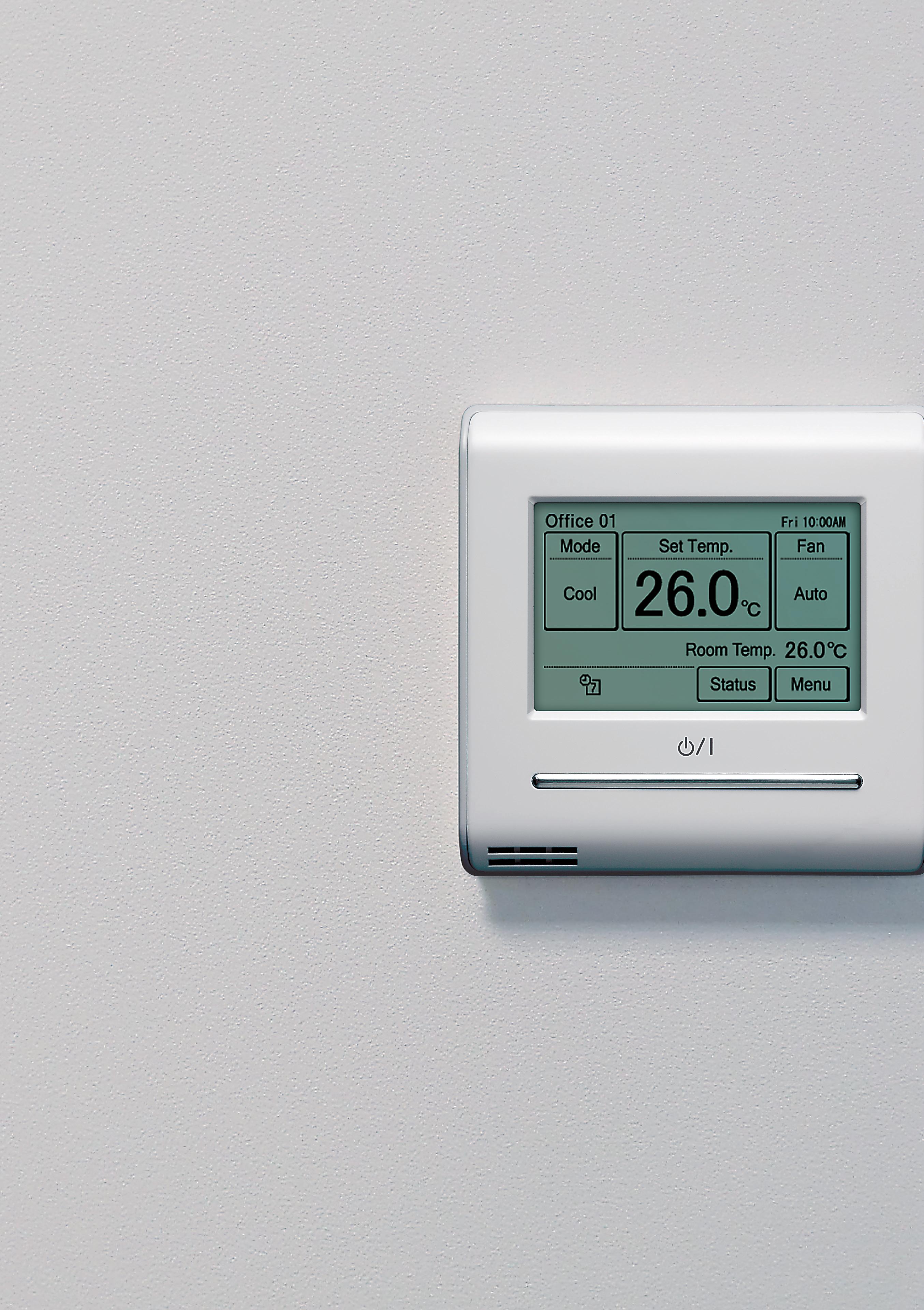
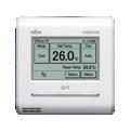
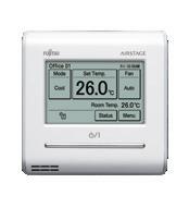
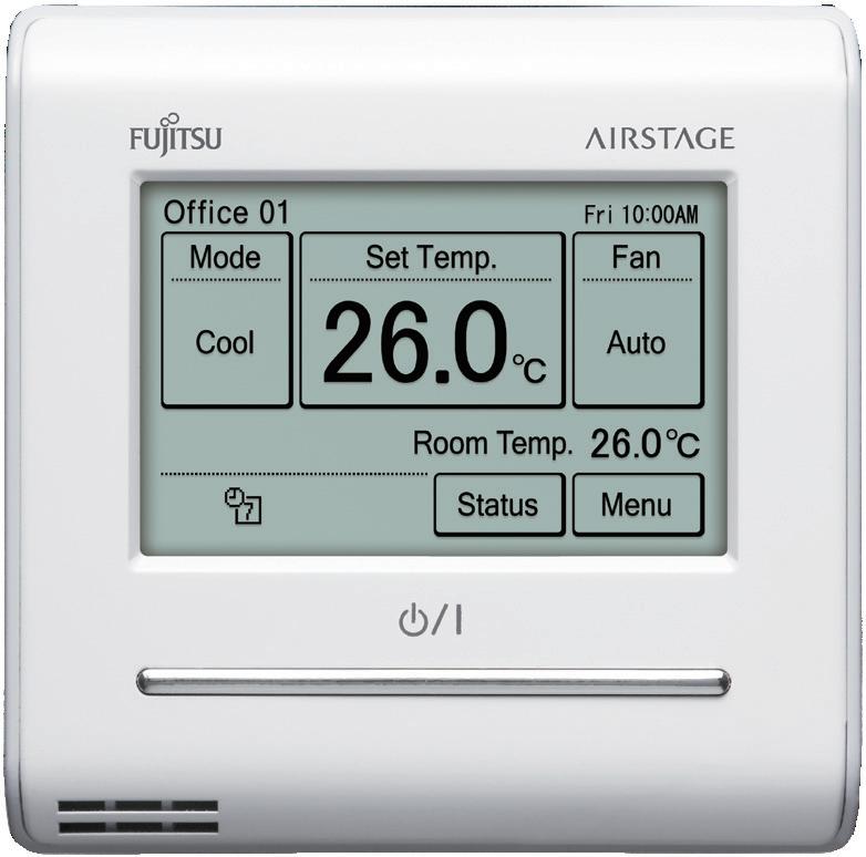
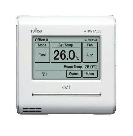
Easy operation with a high-definition large LCD touch panel screen
• Easy touch operation via the touchscreen LCD panel
• Built-in weekly / daily timer (ON / OFF, temp, mode)
• Backlight enables easy operation in a dark room
• Room temperature display
• Control up to 16 indoor units
• 12 different languages (English, Chinese, French, German, Spanish, Russian, Polish, Italian, Greek, Portuguese, Turkish and Dutch)
• 2-wire type
Functions
• In addition to the individual control, various energy saving controls can be utilised via the controller.
• Indoor temperature can be detected accurately by the inclusion of a thermo sensor in the body of the wired controller.
• Backlight enables easy operation in a darkened room.
• The backlight setting can be adjusted for 30 or 60 seconds.
• Backlight activates while the controller is in use and turns off 30 or 60 seconds after the operation stops.
Displays setting status and limitations
• The remote controller settings can be easily checked.
Summer time display
• This function can be set easily from the Menu screen.
Child lock
• Lock / unlock method: push the ON / OFF button and the screen (4 seconds).
Name registration
• Remote controller names can be registered in the remote controller screen.This makes it easy to identify the indoor unit you want to control in the room.
Custom Auto
• Maintains 2 separate set points for heating and cooling
• Automatically changes mode between heating and cooling
* This function is not available for some models.
Auto OFF timer
• The indoor unit is automatically turned off when it reaches the preset operating time frame
• The time frame of the “Auto off timer” allows flexibility for setting and scheduling
• Can be set to turn off in 30 to 240 minutes
Uses non polar 2 wire type
• Incorrect wiring can be prevented by using non-polar 2-wire
2 schedules weekly timer
• 2 schedules, for example summer and winter can be set
• 8 settings are changeable per day of week (setting items: On / Off, temperature, mode, time)
Auto address setting / setting position notification
• When using the touch panel controller to control a remote controller group, new functionality enables the controller to set the respective RC addresses
• After the addresses are assigned these can be confirmed from the indoor unit
Error history display
• Errors that occur in the indoor unit or or on the remote controller are saved in the error history
• A maximum of 32 error incidents can be saved
Set temperature auto return
• The setting temperature automatically returns to the previous temperature setting
• The time range in which the set temperature can be changed is 10 to 120 minutes
Set temperature upper and lower limit
• The set temperature range can be set for each operation mode (cooling / heating / auto)
Specifications
UTY-RSRYT
UTY-RHRYT (without operation mode)
Compact remote controller provides access to basic functions
• Up to 16 indoor units can be controlled with one remote controller
• Suitable for hotels or offices as it is easily operated with no complex functions
• Simple and stylish design to match stylish interiors
• Large LCD screen and simple operation buttons
• Backlight: white coloured backlight on monitor enables easy operation in dark environments
• 2-wire type
Functions
• Vertical louvre control:
Vertical airflow direction can be adjusted for Mini Duct & Slim Duct types, and cassette types, using the auto louvre option. This suits indoor units installed in applications such as hotels and conference rooms.
• Room temperature set point limitation:
The Simple Remote Controller can assist with management of energy usage in small buildings without the central control unit.
• Built in room temperature sensor:
The Simple Remote Controller detects actual room temperature and controls room climate accordingly.
Specifications
DC12V is supplied by indoor unit.
UTY-LNHY
Simple and sophisticated operations with a choice of 4 daily timers
• A single controller controls up to 16 indoor units.
Functions
Select from 4 different timer programs : ON / OFF / program / sleep
Program timer: The program timer operates the ON and OFF timer once within a 24 hour period.
Sleep timer: The sleep timer function automatically corrects the set temperature according to the time setting to prevent excessive cooling or heating during sleep hours.
Cooling operation / dry operation
When the sleep timer is set, the set temperature automatically rises 1˚C every hour. The set temperature can rise up to a maximum of 2˚C.
The code selector switch prevents indoor units from unintended control. (Up to 4 codes can be set.)
Wide and precise
Heating operation
When the sleep timer is set, the set temperature automatically drops 1˚C every 30 minutes. The set temperature can drop to a max. of 4˚C.
During installation work, address setting can be performed using the wireless remote controller, thus eliminating manual switch setting.

Specifications
Option required to control ducted type units via a Wireless Remote Controller
• Up to 16 indoor units can be controlled with one remote controller
• Suitable for hotels or offices as it is easily operated with no complex functions
* The wireless remote controller (model: UTY-LNHY) is necessary separately
Functions
Wiring connection

Specifications
UTY-LRHYB1
Cassette type indoor unit can be controlled with the Wireless Remote Controller
*The wireless remote controller (model: UTY-LNHY) is required.
Functions
Wiring connection
Specifications

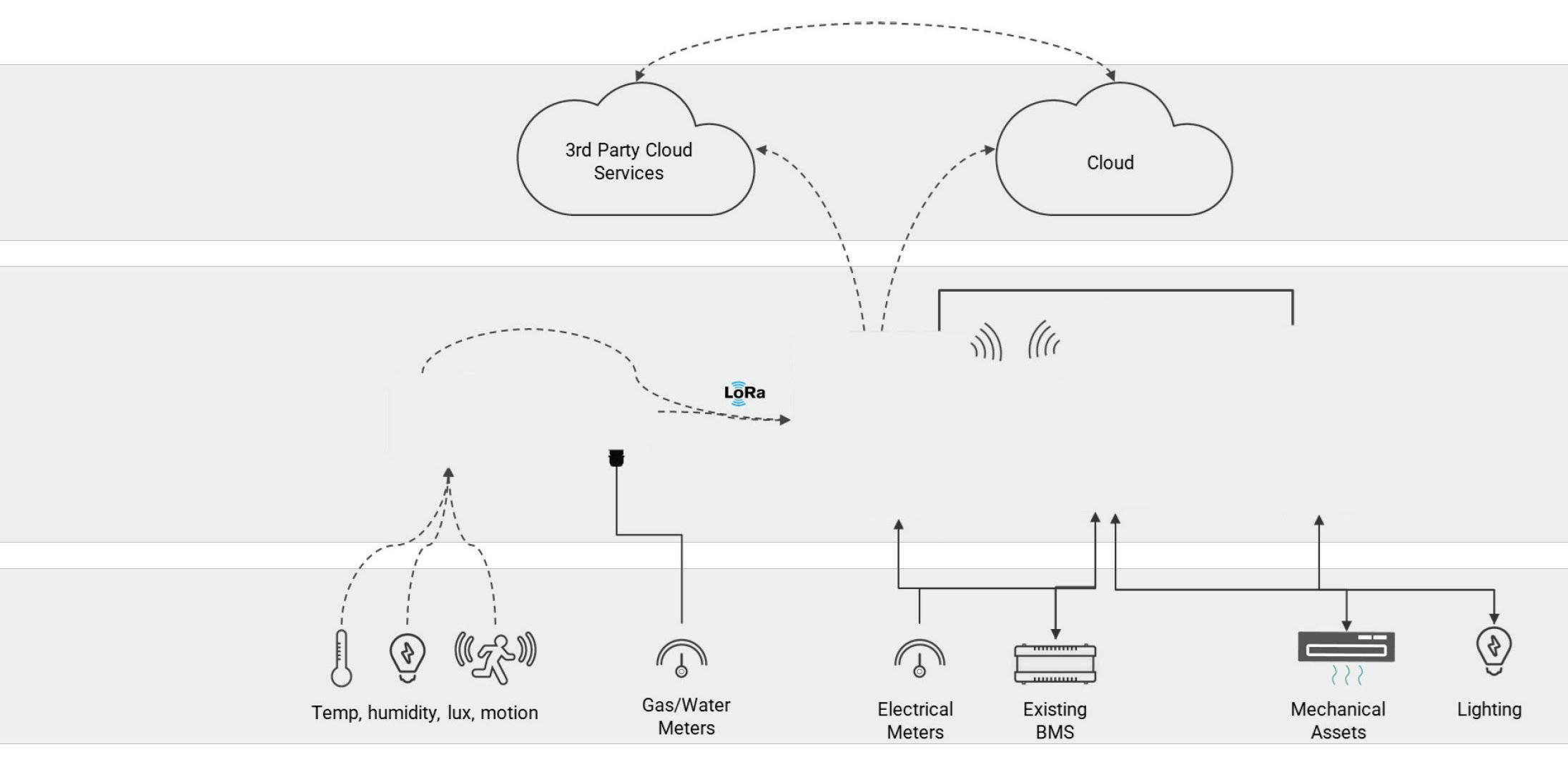
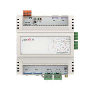
Fujitsu’s anywAiR iO is a smart building solution that integrates wired, wireless and Internet of Things (IoT) technologies to provide advanced control and monitoring over HVAC systems and other building management assets. BACnet, MODBUS and LoRa® equipment can all be integrated using this Muti-Language system.
• Comprehensive Control: It allows for seamless control and monitoring of HVAC equipment and other building assets, optimising operating periods and maintenance cycles to reduce costs and improve efficiency.
• Integration: The system can integrate with existing building infrastructure, making it easier to implement without extensive modifications.
• Scalability: The solution is designed to be easily scalable, allowing for quick installation and connection of new sensors.
• Data-Driven Decisions: By leveraging data analytics and automation, anywAiR iO enables building owners and operators to make informed decisions, optimising efficiency and sustainability.
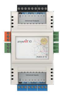
System Architecture
• For more information on anywAiR iO, scan the QR code or visit: www.fujitsugeneral.co.nz/anywair-io
• To discuss a personalised control solution, contact your local Fujitsu Business Manager.

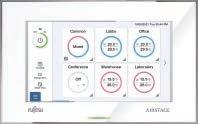
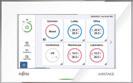
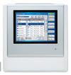
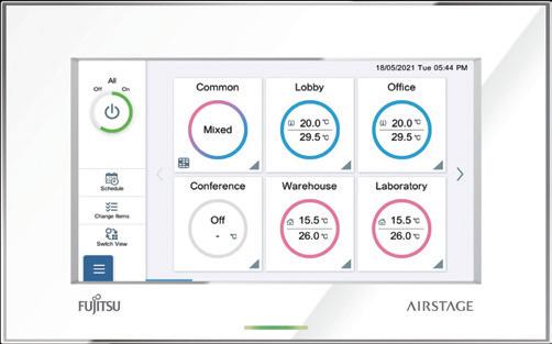
For small and medium-sized buildings and tenants
• Individual control and monitor of 100 indoor units
• 7.0inch TFT colour screen
• High visibility and easy operation
• Room temperature display by indoor unit sensor & remote controller sensor
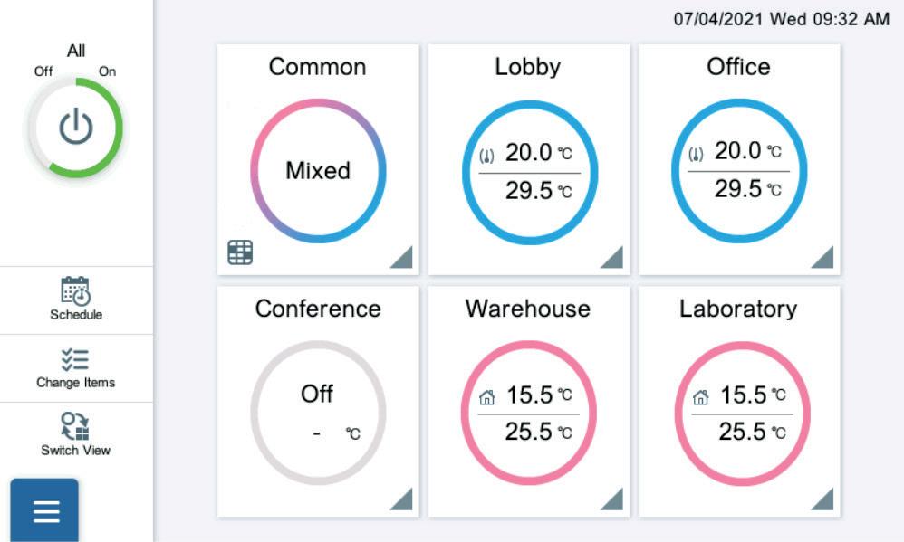
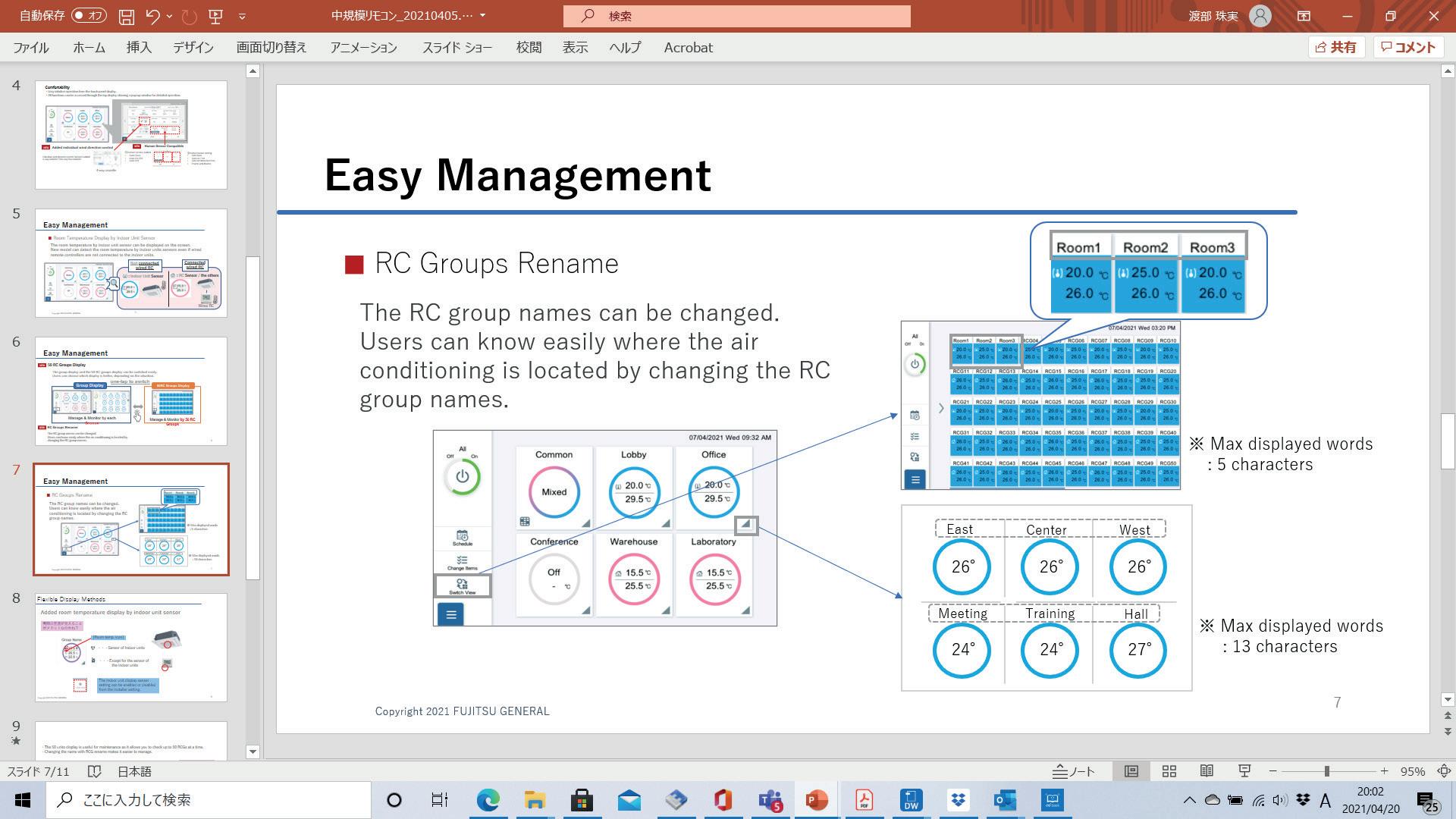
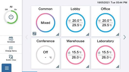
The remote controller group names can be changed. Users can know easily where the air conditioning is located by changing the remote controller group names.
• Easy intuitive operation from the touch panel display.
• All functions can be accessed through the monitoring screen showing a pop-up window for detailed operation.
Remote monitoring / Remote operation
New central remote controller can control your tenant’s air conditioner anytime and anywhere.
When the central remote controller manages the indoor units of some tenants, air conditioning of each tenants can be managed separately online.
Increased the Number of Accounts
Annual Schedule
• An annual schedule can be arranged for each remote controller group or user-defined group
• Allows for the programming of special settings for weekends, holidays and store closings throughout the year
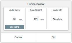
Trouble support function
Display error details Display descriptive explanation when an error occurs
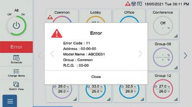
Sensor value monitoring function
Monitor sensor data of indoor unit / outdoor unit, send mail
Notify room temperature by email*
Notify by e-mail when the temperature around the air conditioner is too high or too low
*:This function is available only when using wired remote controller.
Low Noise Schedule
• Low noise operation of outdoor units can be scheduled
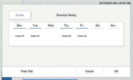
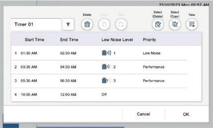
Automatic return to set temperature
A function that automatically returns the changed temperature to its original value over time.
Specifications
Model name
Power supply
Dimensions (H x W x D) mm
• Large-sized 7.5-inch TFT colour
• LCD easy touch operation
• Stylish shape and design to suit all applications
• Up to 400 indoor units can be controlled
• Selectable 2 display types (icon / list) in monitoring mode
• Supports 7 different languages - English, Chinese, French, German, Spanish, Russian, Polish
• Mounted with LAN interface for remote control and operation, external input / output with emergency stop and group ON / OFF
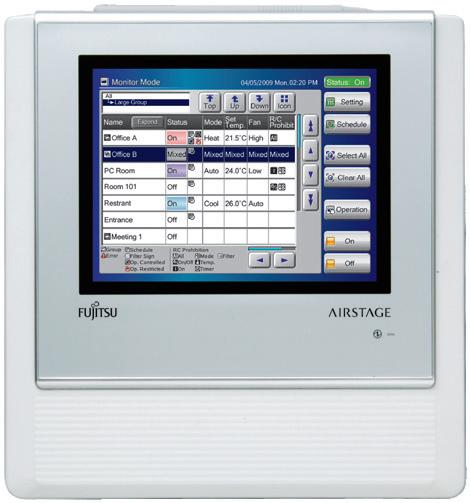
Functions
• Wide range of simple-to-understand icons
• Operation can be selected using your finger or the dedicated stylus pen by pressing the appropriate on-screen icon.
• Back colour identifies current control operation: blue for monitoring; green for operational control.
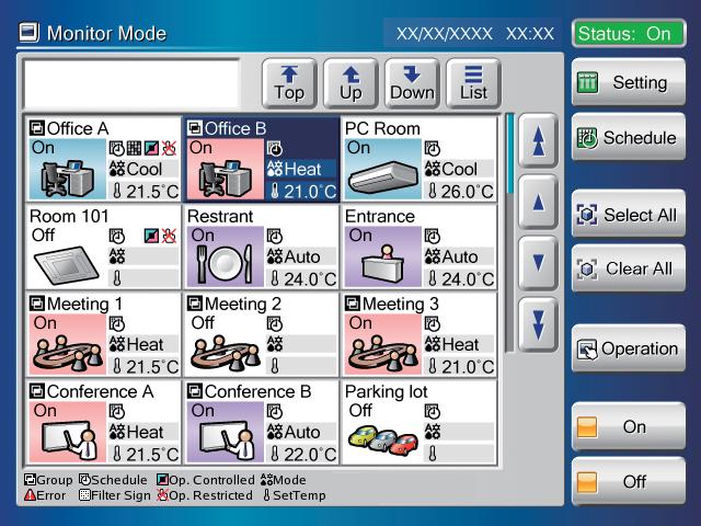
• Flat touch screen is easily cleaned
• Non glare coating on touch panel controller minimises fingerprint marking
• Easy to remove front cover
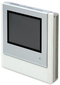

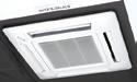
• The touch panel controller is easily mounted to the wall
• The flat back surface allows the controller to be installed wherever required
• No additional components are required for installation
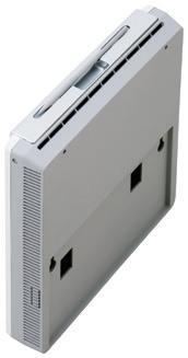
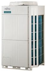
• Control and monitor Fujitsu air conditioners via LAN or Internet
• Allow the user or tenant to manage only assigned equipment by their PC or tablet from anywhere
• Error messages can be notified automatically by email upon an error occurrence to enable the issue to be handled promptly
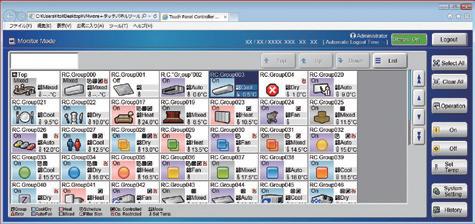
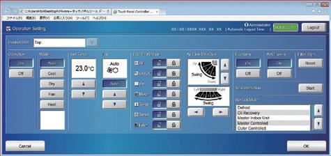

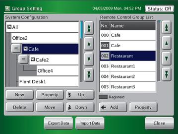

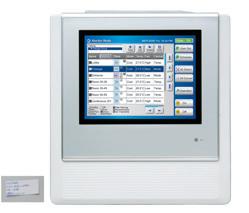


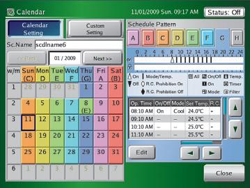
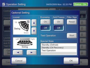
Smart phone Tablet
Model name Browser
Nexus 6P (Android 7.1.1) or later Google Chrome 5.5 or later
iPhone 7 (iOS 10.1) or later Safari 10 or later
Not only operations but also detailed settings such as schedule or group settings can be operated from remote locations.
Model name Browser iPad Pro 9.7inch (iOS 10.2.1) or later Safari 10 or later
The administrator can register multiple users to permit which indoor unit(s) and which functions can be accessed.


Available in 7 different languages- English, Chinese, French, German, Spanish, Russian and Polish as standard. Additional languages can be integrated on a remote device by creating a language database. Additional languages are displayed only on the remote device. The touch panel controller cannot be configured to display these additional languages.

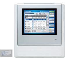


Functions
• Electricity charge apportionment can be utilised to easily attribute power usage to each tenant based on their usage
• Apportionment charge / bill calculation
• Tenant (block) setting
• Common facilities apportionment setting
• Rated power consumption allotment setting
• Individual calculation for both cooling and heating
• Electricity meter supported
Function overview
1) This function enables a schedule to be set within the system to adjust the timer to summer time at the appropriate time to ensure the time matches the time zone.


Automatic clock adjustment
2) The time setting of each controller can be set from the one location.
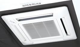
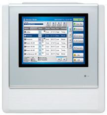
Users can choose from 4 low noise levels, depending on the installation environment.
The operation time can be set using the timer.

Custom Auto
• Maintains 2 separate set points for heating and cooling
• Automatically changes mode between heating and cooling
* This function is not available for some models.


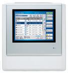
Air conditioning control function
On / Off
Operation mode setting
Fan speed setting
Room temp. set point limitation
Up / down air direction flap setting
Right / left air direction
Individual louvre control
Anti freeze
Various energy saving controls
: Supported : Optional function - : Not supported yet
*1 Only setting cancellation can be operated.
*2 This function is available only through external input control.
*3 This function is available only when using wired remote controller.
Specifications
Model name
Power supply
UTY-APGXZ1
System Controller offers advanced integrated monitoring and control of the VRF network system from small to large scale buildings.
• Up to a maximum of 4 VRF network systems, 1600 indoor units, and 400 outdoor units can be controlled
• In addition to the air conditioning control function, central remote control, electricity charge calculation, schedule management and energy saving functions ensure the building manager and owner needs are met
UTY-ALGXZ1
System Controller Lite has functions suited for air conditioning management in small and medium scale buildings.
• Up to a maximum of 1 VRF network system, 400 indoor units, and 100 outdoor units can be controlled
• In addition to air conditioning precision control function, a variety of management software is available as an option to give customers a wide range of choice
• Click and operate: The property is shown visually from the perspective most suitable for operation and operated accordingly (Click and Operate). You can select from among the 4 displays of site, building, floor, or list.
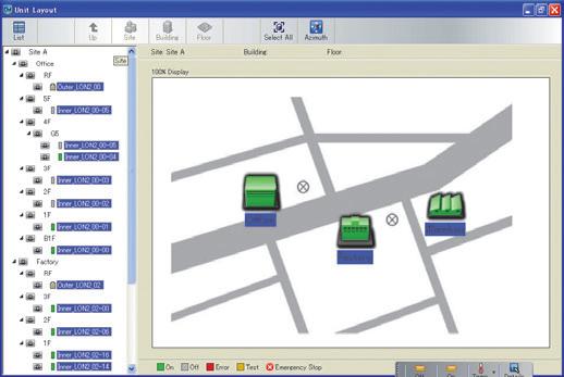

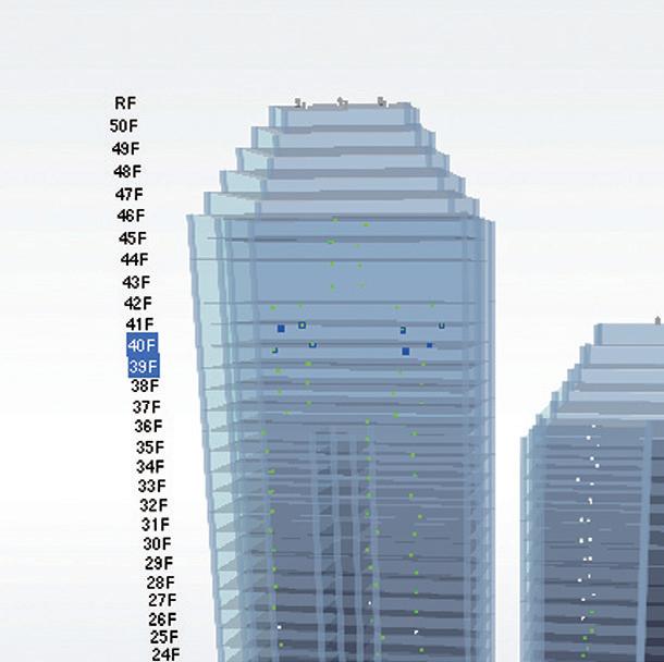


• Define custom groups for batched control: Indoor units can be grouped for simple batched control from a tree menu. Grouping by hierarchal structure, such as by section, division or department is possible.
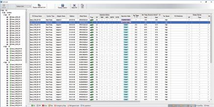

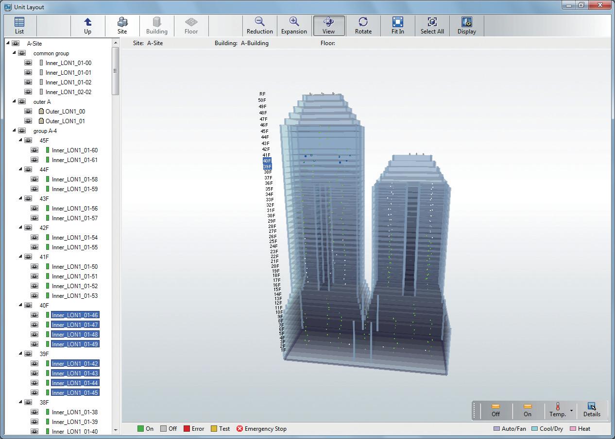

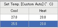
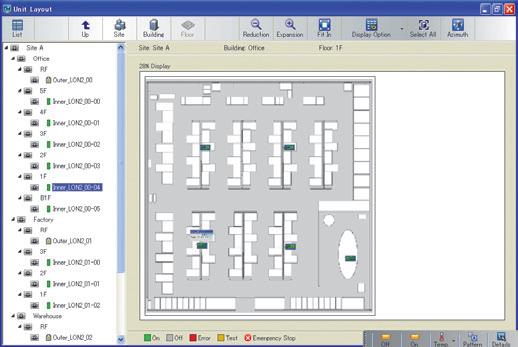

Standard for System Controller and System Controller Lite
Schedule management
• Annual schedules can be set for each remote controller group / user defined group
• Start / stop, operating mode, remote controller prohibition, and temperature settings can be set up to 143 times per day at 10 minute intervals for up to 101 configurations for each remote controller group
• Allows programming of special settings for holidays, including public holidays, for a complete year
• Low noise operation of the outdoor unit can be scheduled
Diverse control of indoor unit and outdoor unit
• Indoor unit operation state, operation mode, etc. are displayed
• Indoor unit start / stop and operation mode switching
• Room temperature set point limitation
Remote controller prohibition
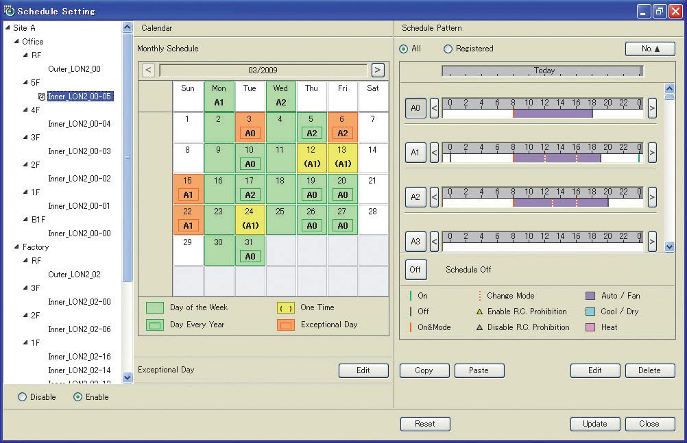
This prohibits changes to the operation mode, temperature, start / stop, etc.
Error display and email notification
Errors are notified with pop-up message, audible sound and email in real time when errors occur. Errors for the past year are logged and can be reviewed at any time.
Operating and control record
Displays the history of operation status and control.
Database import / export
Imports / exports registration data, layout data, and image data. Only the administrator can make this setting.
Automatic clock adjustment
The time setting of each controller can be set centrally with one command.
Standard for System Controller
Option for System Controller Lite UTY-PLGXA2
Electricity charge apportionment calculation framework
Suppose you want to find the power consumed by the air conditioners of each tenant from the electricity charge for each month. With electricity charge apportionment function, the used energy apportionment ratio will be provided, calculating in detail the energy consumed by the units within each tenancy.
This information is then used to calculate the charges for the electricity consumed for air conditioning by each tenant from the total electricity charges in the bill from the electric power company. (See figure to the right.)
The detailed calculation takes into consideration variables such as unused rooms and night-time electricity charges and shows them in the charge calculation sheet .


Standard for System Controller
Option for System Controller Lite UTY-PLGXR2
The System Controller may be used on site or remotely over various networks for remote central control.
System Controller requires 2 software applications working together. VRF Controller runs on site and communicates with the VRF System. VRF Explorer runs remotely and provides user interface and communicates with the VRF Controller. VRF Controller and the VRF Explorer program may operate on a single PC or on different PCs separated by a network.
By using VRF Explorer software, one PC can perform central control of 10 VRF System sites with a maximum 20 buildings per site.

operation Remote central control


PC and smartphones can be used as a simple remote controller.
• ON / OFF
• Temperature setting
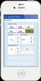
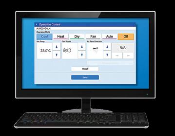
Option for System Controller UTY-PEGX
Option for System Controller Lite UTY-PLGXE2
A variety of energy saving operations can be set and managed depending on the season, weather, and time period.
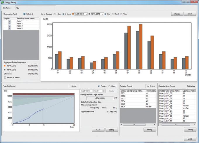
Energy saving graph data: this graph compares the electricity consumption with the previous month and previous year to make it easy to analyse the energy saving effect.
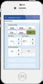


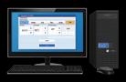
Indoor unit lead lag operation
The operation of indoor units can be automatically rotated within a group in accordance with the set annual schedule to reduce power consumption while maintaining comfort. The indoor unit operation stop rate can be selected.
Peak cut operation
A power meter is connected to detect the total power consumption by shifting the indoor unit set temperature, turning the indoor unit forced thermostat off, and taking other measures to carefully control the power consumed to maintain target power consumption set for the specified time. The indoor units to be controlled can be grouped and the control level can be set.
Outdoor unit capacity limit
Outdoor unit capacity limit function switches the outdoor unit capability upper limit to suppress power consumption during hot summers and cold winters by averaging the power saving effect of each refrigerant system. You can select from 50% or more of the capacity upper limit.
Schedule
Electricity charge apportionment
Apportionment charge / bill calculation
Tenant (block) setting
Common facilities apportionment setting
Rated power consumption
consumption monitor
import / export
clock adjustment
Available. - Not available. * Power calculation application software is necessary, please contact your local Fujitsu General representative.
Personal computer system requirements
The required PC specifications are shown in the following table.
System Controller
Operating system
System Controller Lite
• Microsoft® Windows® 7 Home Premium (32-bit or 64-bit) SP1, Windows® 7 Professional (32-bit or 64-bit) SP1
• Microsoft® Windows® 8.1 (32-bit or 64-bit), Windows® 8.1 Pro (32-bit or 64-bit)
• Microsoft® Windows® 10 Home (32-bit or 64-bit), Windows® 10 Pro (32-bit or 64-bit) [Supported languages] English, Chinese, French, German, Russian, Spanish, and Polish
CPU Intel® CoreTM i3 2 GHz or higher
Memory • 2 GB or more (for Windows® 7 [32-bit]) • 4 GB or more (for Windows® 7 [64-bit], Windows® 8.1, and Windows® 10)
HDD 40 GB or more of free space
Display 1024 x 768 or higher resolution
•Ethernet port (for accessing the Internet using LAN) or modem (for accessing the Internet using a public telephone line)
•USB ports (maximum of 6 ports)
(Required only for the server PC that works as VRF Controller)
Interface
Graphic accelerator
- Maximum of 2 USB ports are required for WHITE-USB-KEY / WibuKey connection
- Maximum of 4 USB ports are required for Echelon® U10 USB Network Interface
* Maximum number of required USB port depends on applicable system configuration
Microsoft® DirectX 9.0c compatible
Software Adobe® Reader 9.0 or later
•Ethernet port (for accessing the Internet using LAN) or modem (for accessing the Internet using a public telephone line)
•USB ports (Maximum of 6 ports)
(Required only for the server PC that works as VRF Controller)
- Maximum of 4 USB ports are required for WHITE-USB-KEY / WibuKey connection
- 1 USB port is required for Echelon® U10 USB Network Interface
* Maximum number of required USB ports depends on applicable system configuration
• Echelon® U10 USB Network Interface – TP / FT-10 Channel (Model number: 75010R) (Required for each VRF Network.)
<PACKING LIST>
*1 Software protection key to be inserted in a USB slot running System Controller or System Controller Lite. System Controller or System Controller Lite may only run on a PC with WHITE-USB-KEY. However, WHITE-USB-KEY is not required for remote VRF Explorer software.
4
1,600
400
• Enables the connection of medium to large sized BMS to VRF network system via BACnet, a global standard for open networks
• A maximum of 1600 indoor units with 4 VRF network systems (a maximum of 400 indoor units and 100 outdoor units for one network system) can be connected to one BACnet Gateway
• Control or monitor VRF network system from BMS via BACnet Gateway
• Compatible with BACnet (ANSI / ASHRAE-135-2012) application specific controller (B-ASC)
• Compatible with BACnet / IP over Ethernet
• Scheduling, alarm and event functions as well as electricity charge apportionment function are provided in the BACnet Gateway
• The connection between VRF network system to personal computer is possible via small U10 USB interface. However, both U10 USB interface and personal computer are field supplied items
• Available for use in 7 different languages, English, Chinese, French, German, Spanish, Russian, Polish
Functions
Personal computer system requirements
Operating system


• Microsoft® Windows® 7 Home Premium (32-bit or 64-bit) SP1, Windows® 7 Professional (32-bit or 64-bit) SP1
• Microsoft® Windows® 8.1 (32-bit or 64-bit), Windows® 8.1 Pro (32-bit or 64-bit)
• Microsoft® Windows® 10 Home (32-bit or 64-bit), Windows® 10 Pro (32-bit or 64-bit) [Supported languages]
English, Chinese, French, German, Russian, Spanish, and Polish
CPU Intel® CoreTM i3 2 GHz or higher
Memory • 2 GB or more (for Windows® 7 [32-bit])
• 4 GB or more (for Windows® 7 [64-bit], Windows® 8.1, and Windows® 10)
HDD 40 GB or more of free space
Display 1024 x 768 or higher resolution
Interface
• Ethernet port (for getting access to the Internet using LAN)
• USB ports (Maximum of 5 ports)
- 1 USB port is required for WHITE-USB-KEY / WibuKey connection
- Maximum of 4 USB ports are required for Echelon® U10 USB Network Interface
* Maximum number of required USB ports depends on the applicable system configurations.
Software Adobe® Reader 9.0 or later
•Echelon® U10 USB Network Interface – TP / FT-10 Channel (Model number: 75010R) (Required for each VRF Network.)
<PACKING LIST>
Name and shape Quantity Application
WHITE-USB-KEY 1 Includes the software and manuals, license for BACnet Gateway.
• BACnet Gateway enables connection between the BMS and FG VRF System
• A maximum of 128 indoor units and 32 refrigerant system can be connected to a single BACnet Gateway
• Compatible with BACnet (ANSI / ASHRAE-135-2010) application specific controller (B-ASC)
• Compatible with BACnet / IP over Ethernet
Functions
Installation example

BACnet Operator Workstation (B-OWS)
Specifications


Gateway (Hardware)

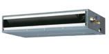

Model name UTY-VBGX
Number of controllable indoor units 128
Number of controllable refrigerant system 32
Number of controllable VRF network 1
Number of connectable units / one VRF network 4
UTY-VLGX
• For connection between VRF network system and a LONWORKS open network for management of small to medium sized BMS and VRF network systems
• The UTY-VLGX permits central monitoring and control of a VRF network system from a BMS through a LONWORKS interface
• Up to 128 indoor units can be connected to one Network Converter for LONWORKS
Functions
Specifications
Model name
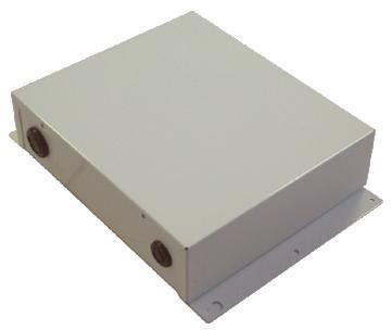
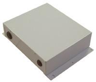
Transmission specifications (BMS side)
Transmission speed
Transceiver
(Echelon® Corporation)
Transmission way form Free topology
Terminal resistor None (It attaches at the terminal of a network)
UTY-VMGX
The MODBUS Converter allows a complete integration of air conditioners into MODBUS Networks
• Compact and lightweight design
• Direct connection to MODBUS network
• Up to 128 indoor units can be controlled in one MODBUS Converter
• The MODBUS Converter permits central monitoring and control of air conditioners from BMS or central controller
Functions


Specifications
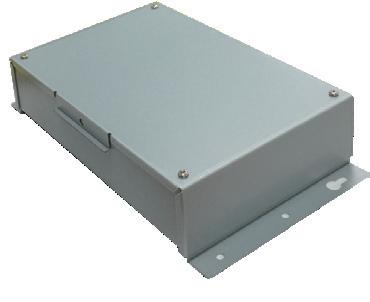

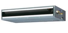
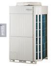
UTY-VKGX
It is possible to control the VRF System from the Central / Home Controller via the KNX network
• The new KNX Convertor enables connection of the Central / Home Controller and FG VRF System
• A maximum of 128 indoor units and 100 outdoor units can be connected to single KNX Convertor
Functions
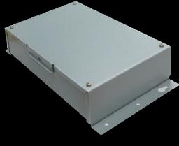
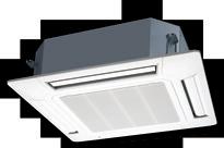
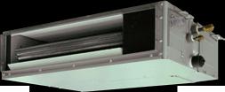
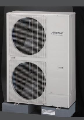
Specifications
UTY-VMSX
The MODBUS Converter allows a complete integration of air conditioners into MODBUS networks
• Simple installation due to small and compact size
• No separate external power supply required
• The MODBUS Converters must be connected one by one in the indoor unit
• The MODBUS controller permits central monitoring and control of air conditioners from BMS / Central / Home Controller
Functions
Specifications
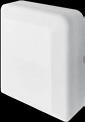
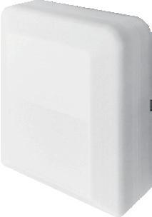
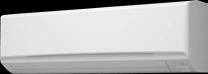
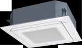
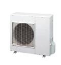
UTY-VKSX
It is possible to control the VRF System from the Central / Home Controller via the KNX network
• New KNX Convertor enables connection between Central / Home Controller and FG indoor unit
• Compact and lightweight design
Functions
Specifications
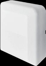
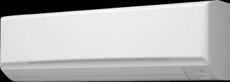
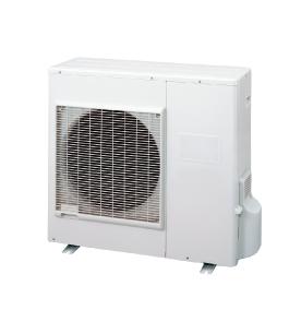
UTY-VTGX (DC power supply type)
The Network Converter offers a total solution to control multiple air conditioning systems.
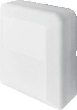
Functions
• The converter is required when connecting single units to a VRF network system
• Administrator can perform total management of single units with a centralised VRF controller
split type unit management Single unit with VRF
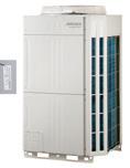
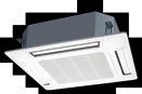
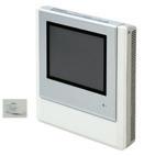
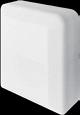
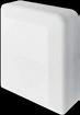
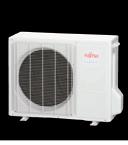
DC power supply type can be powered by indoor unit No power supply construction for converter
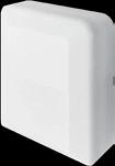
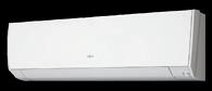

Specifications

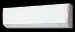
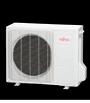
The new
is
and compact, reducing the installation space required
UTY-VSGXZ1
• Transmission line length can be extended up to 3,600m with multiple Signal Amplifiers
• Up to 40 signal amplifiers can be installed in a VRF network system
• A signal amplifier is required
(1) When the total wiring length of the transmission line exceeds 500m
(2) When the total number of units on the transmission line exceeds 64
Functions

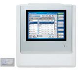
Specifications
Model name UTY-VSGXZ1
Power supply 220-240V 50 / 60Hz, single phase
Input power W 4.5
Dimensions (H x W x D) mm 67 × 288 × 211
Weight g 1,500

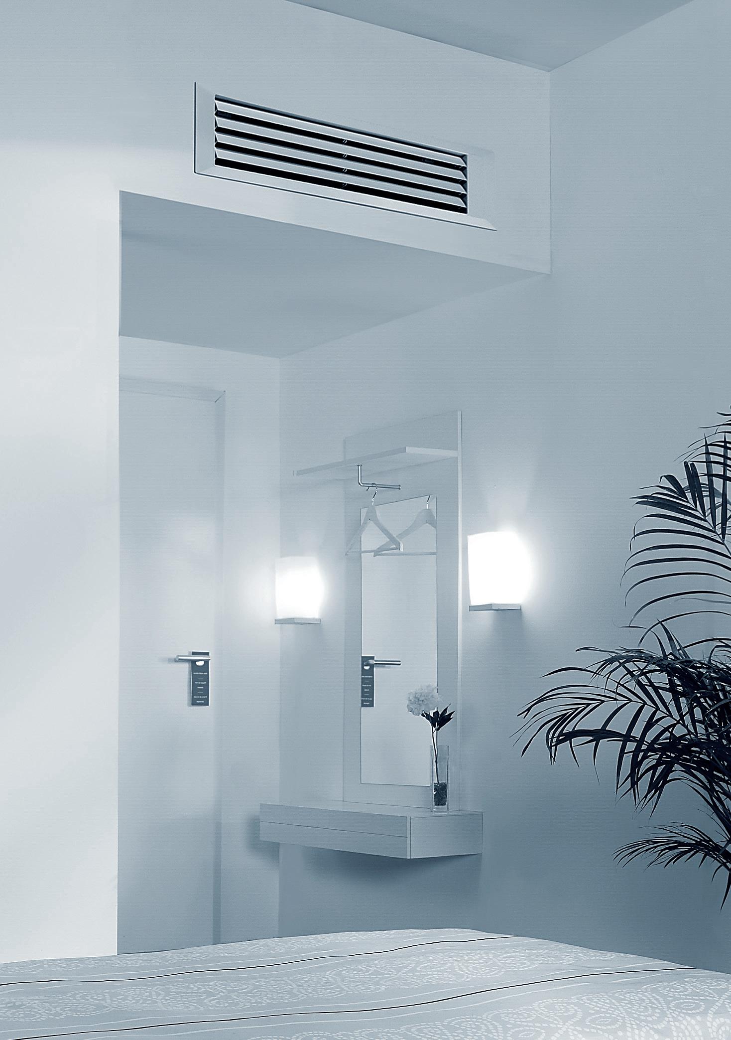
Diverse building air conditioning control functions can be controlled easily by AIRSTAGE™ options.

Various kinds of optional parts are provided such as controllers, adaptors and converters to meet the needs of every user.
AIRSTAGE ™ OPTION
External Power Supply Unit
Auto Louvre Grille Kit
CONTROL SYSTEM LIST
OPTIONAL PARTS LIST
OPTIONAL PARTS
EXTERNAL INPUTS AND OUTPUTS
PIPING AND REFRIGERATION ACCESSORIES
Models
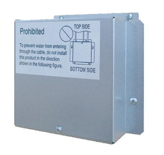
Features
A) Main power shut down can be detected at power shut down detection part.
B) The power for indoor unit expansion valve drive, etc. is supplied. (DC 12V, 5V)
C) Power supply from External Power Supply Unit is notified.
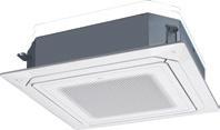
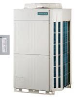
Notes:
• When changing the power supply voltage to AC24V, use a power transformer with an insulated structure that complies with the regulations* of the installation area.
• Indoor units that are powered off and driven by an External Power Supply Unit are handled in the same manner as operation off units in the electricity charge apportionment function. Since standby power may be charged to them, the electricity charge apportionment result for them may not be 0.
Specifications
Dimensions (H × W × D) mm
Models
UTD-GXTA-W
UTD-GXTB-W
UTD-GXTC-W
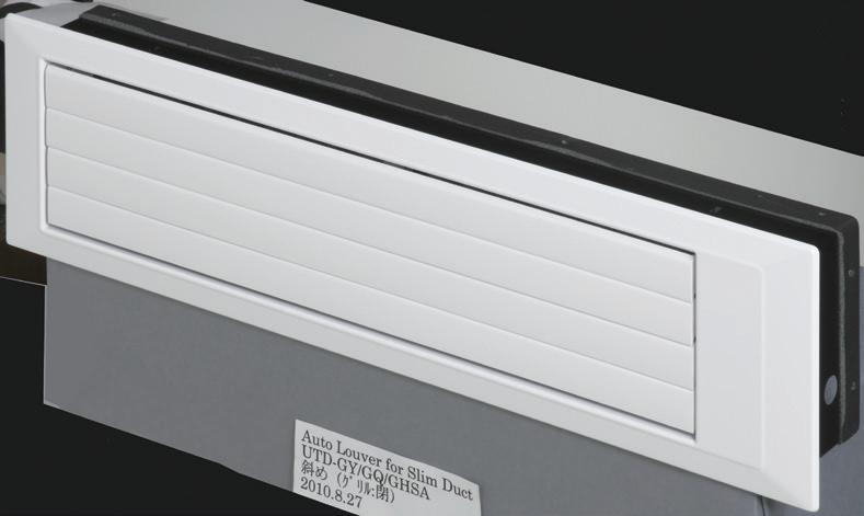
Flexible control
• Operation with indoor unit
The Auto louvre can be operated via the remote controller of the indoor unit.
• Up and down auto swing
• Auto airflow direction and auto swing
• 4 steps selectable
• Auto closing louvre
When the operation of the indoor unit is stopped, the louvre will automatically close.
Specifications Model name
Applicable indoor unit
Power source
Fixing of auto louvre grille
Dimensions
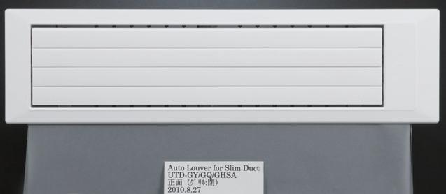
UTD-GXTB-W
UTD-GXTC-W
Connecting with control box of indoor unit
Screw fixing to flange or square duct
Extension square duct limit 1.0m (Max. duct length between indoor unit and grille)
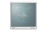
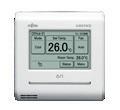


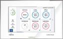


UTY-RNRYT5
UTY-RSRYT, UTY-RHRYT
UTY-LNHY
UTY-DCGYZ3
UTY-DTGYZ1
UTY-APGXZ1, UTY-ALGXZ1
UTY-ABGXZ1, UTY-VBGX UTY-VLGX


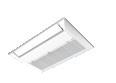
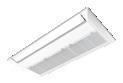


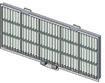

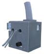


UTD-GXTA-W (007-014), UTD-GXTB-W (018), UTD-GXTC-W (024)
UTD-LF25NA UTD-LF60KA (036/045/060)
Wired Remote Controller KAGAMI
UTY-RVRY
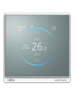
Wireless Remote Controller
UTY-LNHY
IR Receiver Unit
UTY-LBHXD
For Circular Flow Cassette type
For Centralised Control
Central Remote Controller
UTY-DCGYZ3

System Controller
UTY-APGXZ1
UTY-PEGXZ1
Wired Remote Controller (Touch Panel)
UTY-RNRYT5
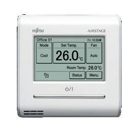
IR Receiver Unit
UTB-TWC, UTY-TRHX
For Duct type
Simple Remote Controller
UTY-RSRYT with operation mode
UTY-RHRYT without operation mode
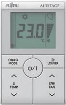
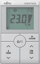
IR Receiver Unit
UTY-LRHYB1
For Cassette type
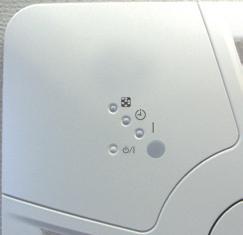
Human Sensor Kit
UTY-SHZXC
For Circular Flow Cassette type
Touch Panel Controller
UTY-DTGYZ1
UTY-PTGXA
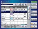
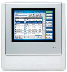
System Controller Lite
UTY-ALGXZ1
UTY-PLGXR2
UTY-PLGXA2
UTY-PLGXE2
UTY-PLGXX2
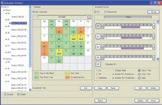
BACnet Gateway
UTY-ABGXZ1
WHITE-USB-KEY (Software Protection Key)
MODBUS Converter for VRF
UTY-VMGX
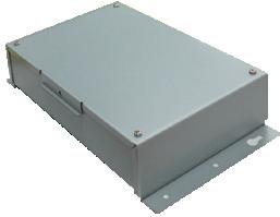
KNX® Convertor for Indoor unit
UTY-VKSX
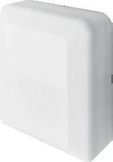
For System Expansion
Network Converter for single split system
UTY-VTGX
DC power supply type
BACnet Gateway UTY-VBGX
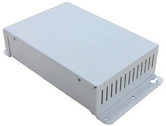
KNX® Convertor for VRF
UTY-VKGX
Network Converter for L ONWORKS
UTY-VLGX
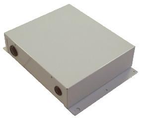
MODBUS Converter for Indoor unit
UTY-VMSX
Signal Amplifier
UTY-VSGXZ1

For Indoor unit
External Power Supply Unit
UTZ-GXXC
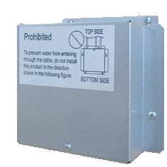
Cassette Grille
UTG-UFYC-W For Compact Cassette type
Cassette Grille
UTG-UGYA-W For Cassette type
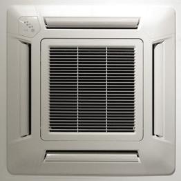
Cassette Grille
UTG-UNYA-W For 1-way Flow type
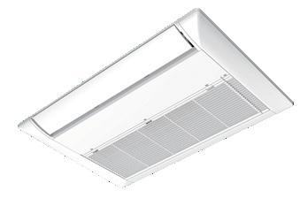
Wide Panel
UTG-AKXA-W For Cassette type
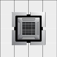
Fresh Air Intake Kit
UTZ-VXAA UTZ-VXRA For Compact Cassette type For Cassette type
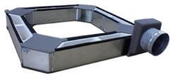
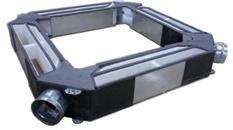
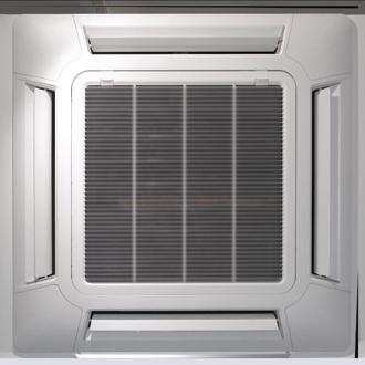
Cassette Grille
UTG-UNYB-W For 1-way Flow type
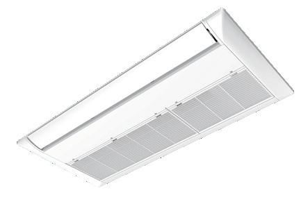
Panel Spacer
UTG-BKXA-W For Cassette type (mm) Panel spacer 50
Air Outlet Shutter Plate
UTR-YDZB For Compact Cassette type
Shuts the 4th outlet when installed in a 3 outlet directional airflow scenario.
Drain Pump Unit
UTR-DPB24T For Ceiling type
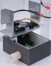
Half Concealed Kit
UTR-STA For Floor type
Cassette Grille
UTG-UKYC-W For Circular Flow Cassette type
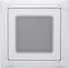
Insulation Kit for high humidity
UTZ-KXRA For Cassette type
UTZ-KXGC For Compact Cassette type
Air Outlet Shutter Plate
UTR-YDZK For Cassette type
Shuts the 4th outlet when installed in a 3 outlet directional airflow scenario.
For Outdoor Unit
Pressure Sensor Kit
UTY-SPWX For V-III
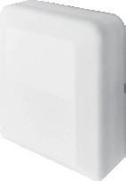
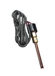
Flange (round)
UTD-RF204
For Medium Static Pressure Duct type / Ceiling type
Long-Life Filter
UTD-LF25NA
UTD-LF60KA
For Medium Static Pressure Duct type For High Static Pressure Duct type
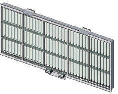
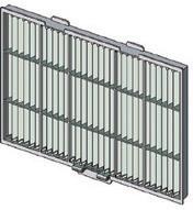
Flange (square)
UTD-SF045T For Medium Static Pressure Duct type
Auto Louver Grille Kit
UTD-GXTA-W (for ARXD007 / 009 / 012 / 014, ARXK007 / 009 / 012 / 014)
UTD-GXTB-W (for ARXD018, ARXK018)
UTD-GXTC-W (for ARXD024, ARXK024)
For Slim Duct type / Mini Duct type
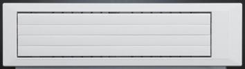
Communication system: External Connect Kit
For Indoor unit
UTY-XWZXZ7
UTY-XWZXZB
UTY-XWZXZC
For RB unit
UTY-XWZXZ6
UTY-XWZXZB
UTY-XWZXZD
UTY-XWZXZE
For Central Remote Controller
UTY-XWZXZ7
UTY-XWZXZ8
UTY-XWZXZA
Remote Sensor Unit
UTY-XSZXZ1
For all Duct type
Remote temperature sensor unit replaces indoor unit return air sensor with sensor from location of remote sensor.
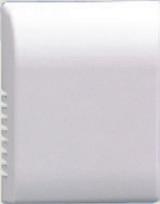
Drain Pump Unit
UTZ-PX1NBA
For Medium Static Pressure Duct type
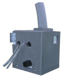
For Outdoor unit
UTY-XWZXZ6
UTY-XWZXZ9
UTY-XWZXZF
For Touch Panel Controller
UTY-XWZXZA
Separation Tube
UTP-AX054A
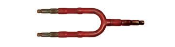
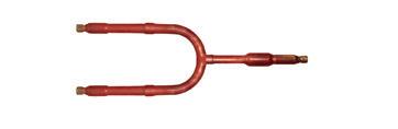
UTP-BX090A Suction
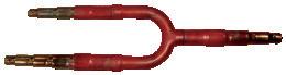
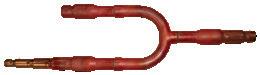
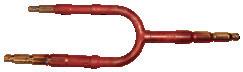
UTR-H0906L / UTR-H1806L
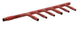
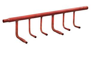
UTP-BX180A
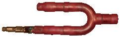
UTR-H0908L / UTR-H1808L
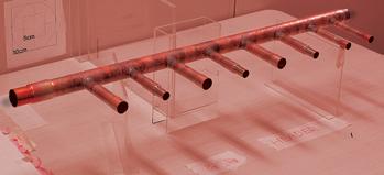
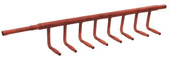
UTP-CX567A
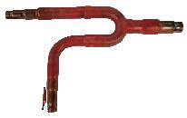
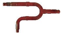
UTP-RX01AH / UTP-RX01BH / UTP-RX01CH Single type
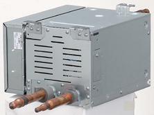
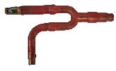
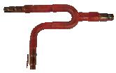
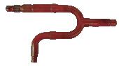
UTP-RX04BH Multi-split type
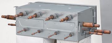
UTP-BX567A
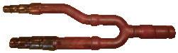
UTP-J0906A / UTP-J1806A


UTP-J0908A / UTP-J1808A


UTP-RX08AH Multi-split type
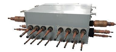
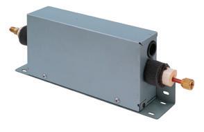
UTP-RX12AH Multi-split type
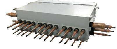
Model name
Header
Outdoor unit Branch kit Model name
Model name
Branches
3-8 Branches
3-6 Branches
UTP-BX090A (forVR-IV)
UTP-BX180A (for VR-IV)
UTP-BX567A (for VR-IV)
UTR-H0908L UTR-H1808L
(for
3-8 Branches UTP-J0908A (for VR-IV) UTP-J1808A (for VR-IV)
UTP-CX567A (for V-IV)
Model name
Application model ASYE007GTEH ASYE009GTEH
RB Unit
UTR-EV09XB
UTP-DX567A (for VR-IV)
*1: In the case of two RB units connected in series ( total 8-branches ), the maximum capacity of connectable indoor units is up to 56.0kW.
UTR-EV14XB
Since we began our air conditioning business in 1971, our products have been popular globally, and we continue to improve, evolve and expand our lineup to exceed our customers’ expectations.
• OUR HISTORY
• WORLDWIDE LOCATIONS
• PROJECT REFERENCES
• GLOBAL DEVELOPMENT AND PRODUCTION BASES
• HIGH QUALITY DEVELOPMENT AND PRODUCTION
• FACILITIES
Fujitsu General's VRF Airstage™ Series has been developed based on our air conditioning technology along with an ongoing investment in research and development.
We o er a series of products suitable for large homes to large scale buildings to meet the various needs of the market.
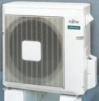
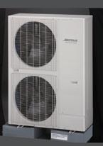
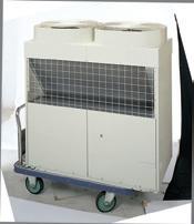


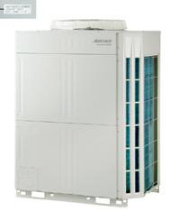
High e ciency and compact design model Extensive lineup from 8HP to 48HP in 2HP increments / Heat Pump
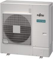
(Wuxi)
Fujitsu introduced inverter technology which used R410A
of Hazardous Substances (RoHS) is an EU directive on the restriction of the use of certain hazardous substances in all consumer
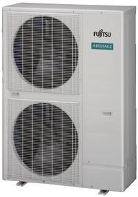
2016 J-III Series
High e ciency and small capacity model 4HP to 6HP / Heat Pump

2017 - 2019 J-IIIL Series
High e ciency and compact design model 10HP to 18HP / Heat Pump
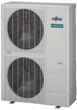

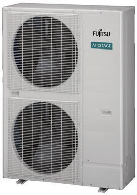
2020 J-IV, J-IVS, J-IVL Series
High e ciency and compact design model 4HP to 18HP / Heat Pump
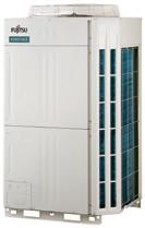
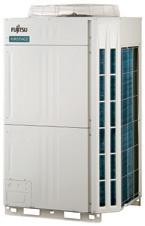
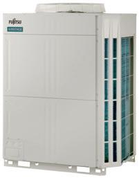
2015 V-III Series
High e ciency and large capacity model
Extensive lineup from 8HP to 54HP in 2HP increment / Heat Pump
2016 V-III TROPICAL Series
Extensive lineup from 8HP to 54HP in 2HP increments / Heat Pump
2020 VR-IV Series
High e ciency and compact design model 8HP to 48HP / Heat Recovery
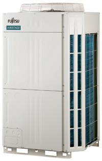
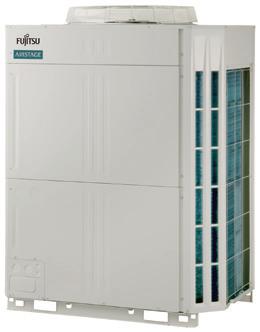
2022
V-III Series Update
Lineup updated (starting from serial number R4) with the latest software to include the New Intelligent Refrigerant Control feature.
Under a system of five bases in Europe, the Middle East, Asia and Oceania, North and South America, and Japan, the company promotes Globalization from a worldwide perspective while emphasizing the actual conditions in each region.
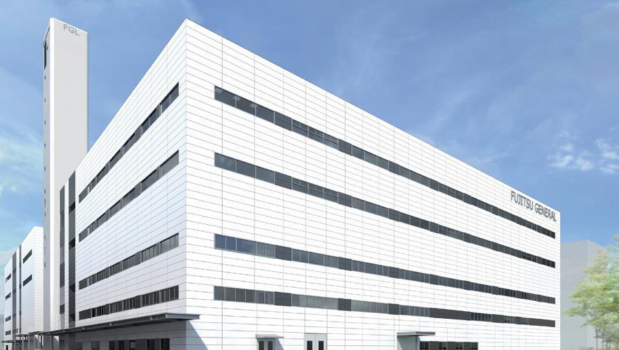
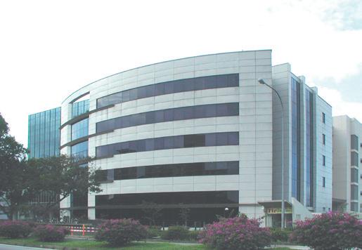

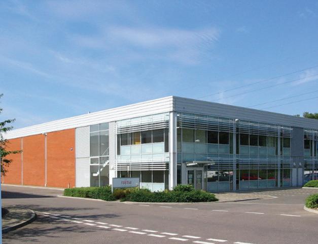

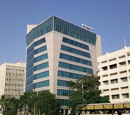
• Fujitsu General Air Conditioning (UK) Ltd.
• Fujitsu General (Euro) GmbH
• Fujitsu General Commercial Air Conditioning Italia S.p.A.
• Kløver Vest Holdings AS (Norway)
• Fujitsu General South East Europe S.A.
• Fujitsu General (Thailand) Co.,Ltd. Bangkok Office
• ABS Aircon Engineers Private Ltd.
• Fujitsu General (India) Private Ltd.
• Fujitsu General (Middle East) FZE
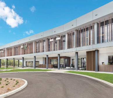
• Fujitsu General Electronics (Suzhou) Co., Ltd.
• Fujitsu General Sales & Trading (Shanghai) Co., Ltd.
• Fujitsu General Limited
• Fujitsu General (Taiwan) Co., Ltd.
• Fujitsu General (Aust.) Pty Limited
• Precise Air Group (Holding) Pty Ltd.
• Fujitsu General New Zealand Ltd.

Highly popular for their excellent quality, energy efficiency, and ease of installation, Fujitsu General’s products are installed in a wide range of buildings around the world, including high-rise office buildings, stores, hotels, public facilities, schools, hospitals, and residences.
1
2
3
4
5
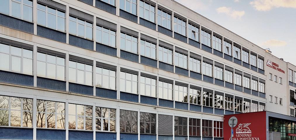
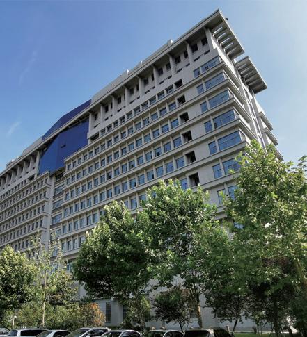
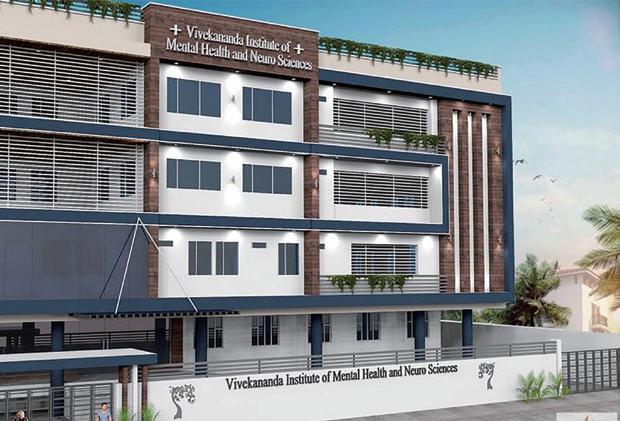

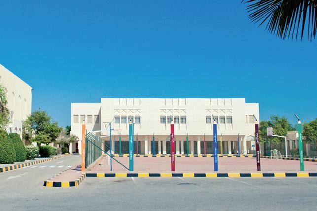

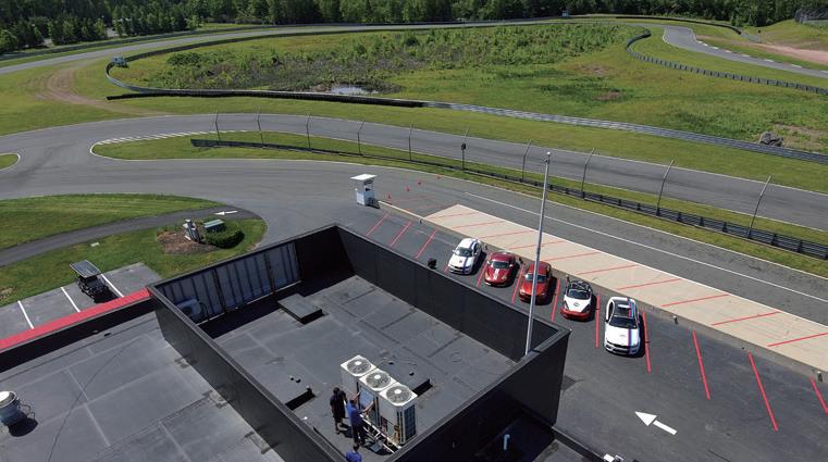
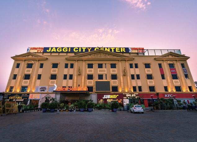
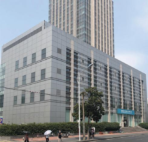
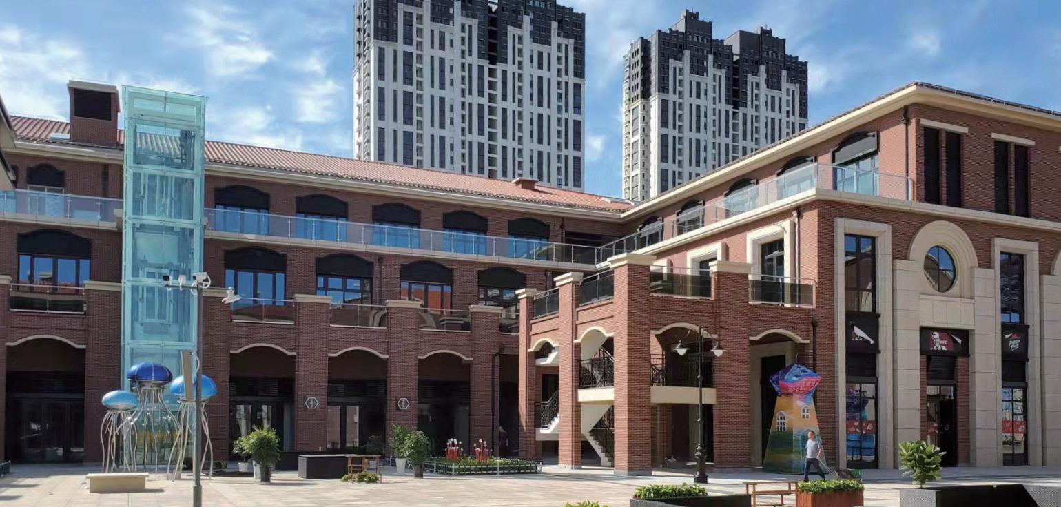
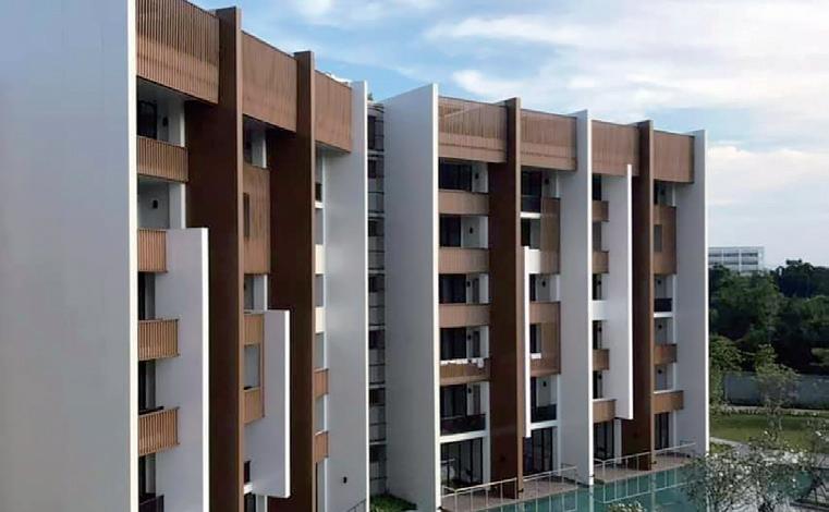


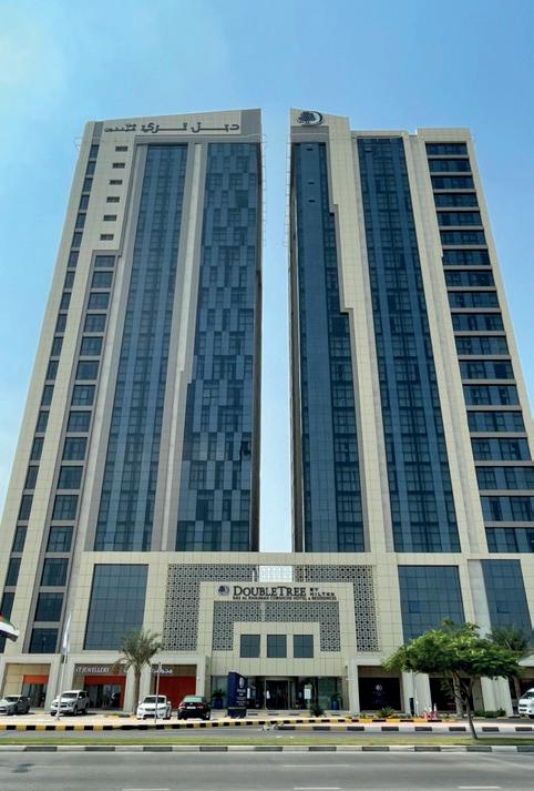
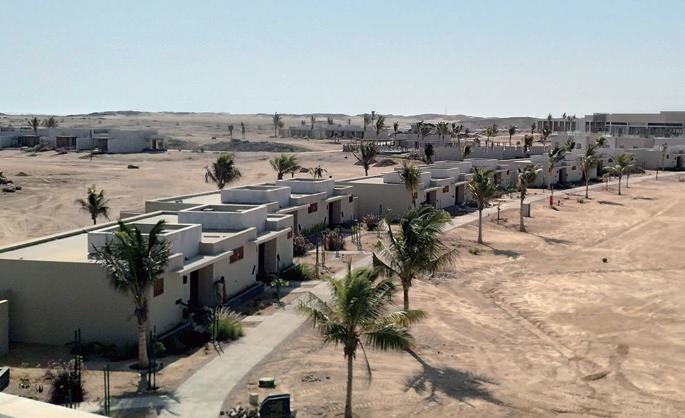
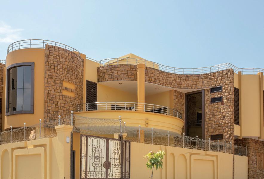
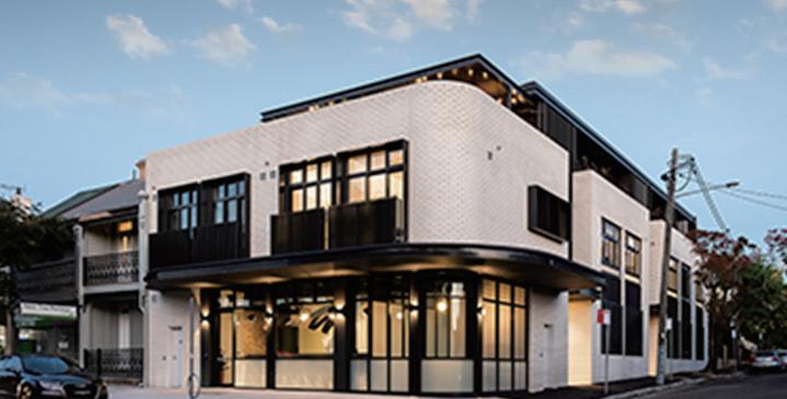
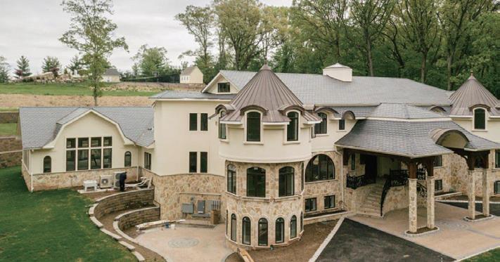
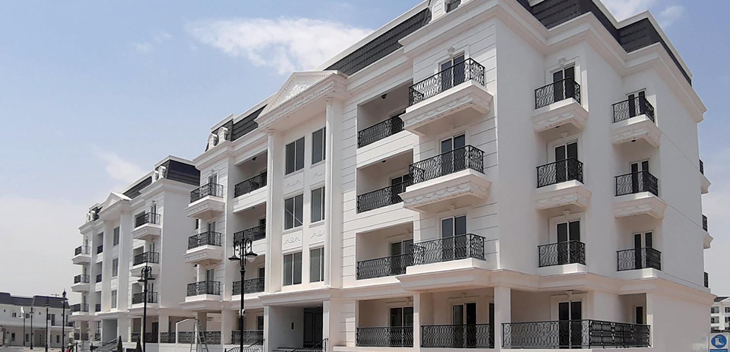
We have established Research & Development bases in five countries from Japan, Europe, Asia, China, and North America to pursue environmental properties and comfort according to the needs of each region.
• Head office
• R&D center
• Manufacturing companies
R&D Center & Technology Research Building

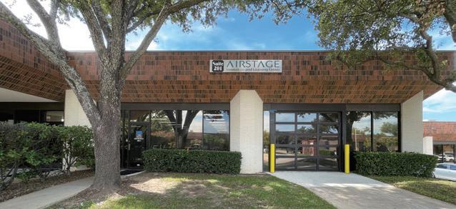
• North America R&D Center - R&D center
• Fujitsu General (Euro) GmbH - R&D center
• FGAHP
Technology research building in Japan Head office
Constructing IoT-based manufacturing
We are implementing a real-time IoT-enabled system to immediately visualise and analyse various information such as facility operating status, assembly line production progress, and parts inventory and transportation status.
This will further enhance the accuracy of production and shipping forecasts in the Head Office and factory management departments.
The system will also help improve activities by employees at production sites, with the aim of improving the efficiency of the production process, the efficiency of parts distribution operations, and the utilisation rates of the
• Fujitsu General Central Air-conditioner (Wuxi) Co., Ltd.
• F.G.L.S Electric Co., Ltd.
Fujitsu General Electronics Ltd.
• Fujitsu General Limited
- R&D center
• Fujitsu General (Shanghai) Co., Ltd.
- R&D center
• Fujitsu General Air Conditioning R&D (Thailand) Co., Ltd.
- R&D center
• Fujitsu General (Thailand) Co., Ltd.
• Fujitsu General (Thailand) Co., Ltd. Factory-2
• FGA (Thailand) Co., Ltd.
• TCFG Compressor (Thailand) Co., Ltd.

Fujitsu General is one of Japan’s leading air conditioning manufacturers with an R&D Centre in Japan. We aim to provide customers with high quality and performance tested products.
Performance Testing
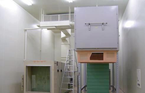
Air Volume Measurement Room
Measures air volumes of the air conditioner from compact room air conditioner models to VRF.
Reliability Testing
Constant Temperature Room Testing product performance in cooling/heating operation under various temperature and humidity conditions.
Calorimeter
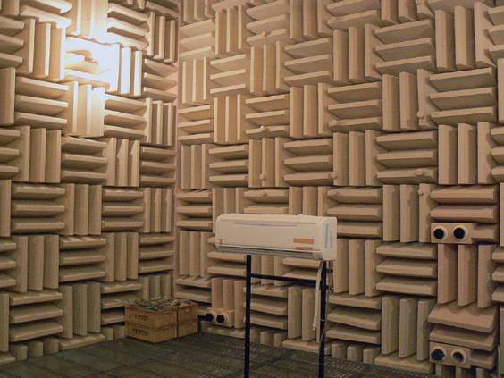
Measures cooling/heating capacity by measuring the inlet and outlet temperatures, humidity, and air volume of the air conditioner.
Silent Room Measures operating sounds of the air conditioner using sound reflection-proof walls and ceiling.
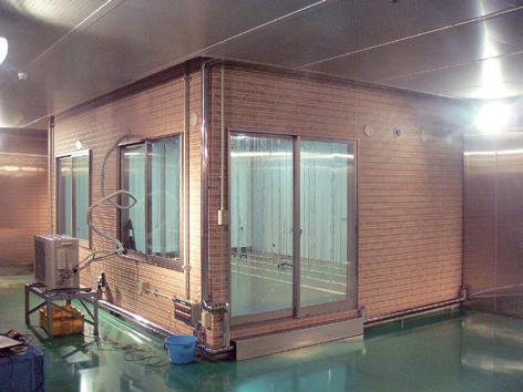
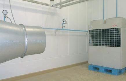
Fujitsu General is one of Japan’s leading manufacturers with an R&D Center in Japan.
We provide our customers with the highest quality and performance using these facilities.
Practical Test Room Tests air conditioner performance within actual house conditions is sustainable.
Transportation & Handling
Shower Test Room Testing electrical box of the outdoor unit is protected by rain waters with Typhoon like wind.
Compressibility testing Vibration testing
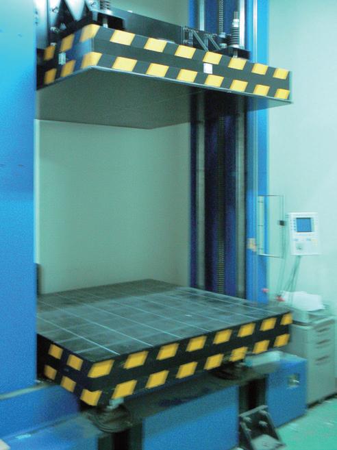
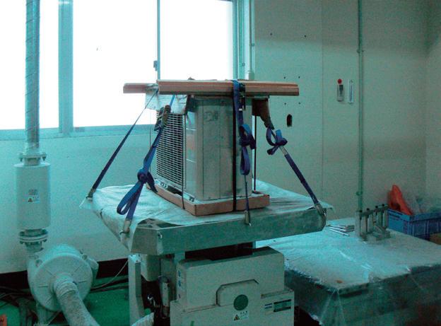
Testing Laboratory
Fujitsu General EMC Laboratory Limited
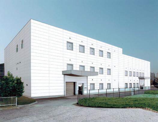
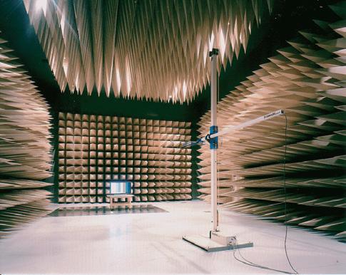

Technology Research Building in Japan’s Head Office
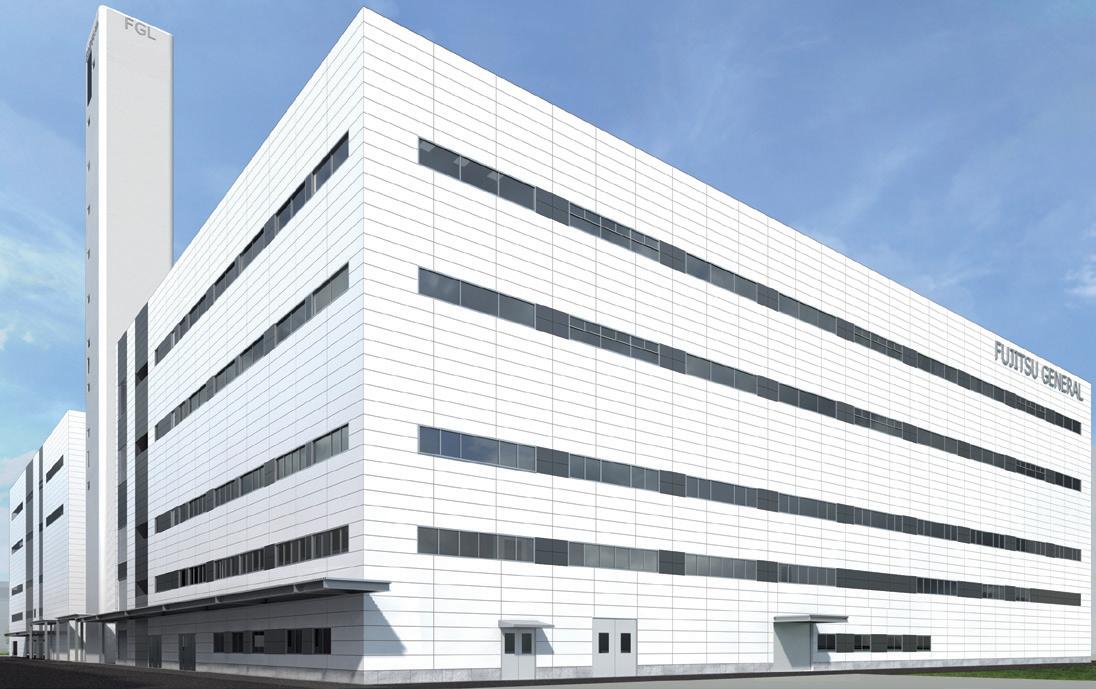
60m Height Difference Testing Tower
Objective is to confirm oil circulation of compressor for reliability
Each of overseas production bases (5 companies) completed the acquisition of ISO 9001 and ISO 14001 individually.
In 2012, overseas sales bases (11 companies) acquired the certification of ISO 14001.
All Fujitsu General factories have acquired ISO 9001, and have built a quality control system common around the world. High quality products are offered to all over the world based on stringent quality inspections.
Receiving inspection
Parts procurement requires a supplier’s test report. European regulation RoHS inspection is also performed by special test department in-house. Total number inspection is performed especially on main parts to remove defectives.

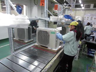
Stringent product quality inspection
Stringent quality inspection is carried out at all production processes. High quality is maintained by stringent checks by inspectors and repetitive inspection.
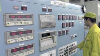
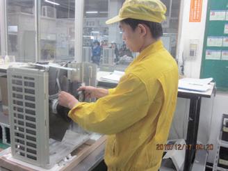
Our support offering methodology is focused on total support. From the stages of design, installation and commissioning through to after sales support.
• AIRSTAGE™ SUPPORT
• AIRSTAGE™ / RAC SUPPORT TOOL
• QUICK SERVICE AND MAINTENANCE
• SERVICE TOOL
• WEB MONITORING TOOL

Fujitsu General provides a variety of product and technical information to engineers and consultants. We also conduct new product research and design support activities. We provide a wide range of support to maintain high quality from design to installation.

We provide information and tools that are useful for air conditioning system design, such as unit performance data and tools that make model selection and estimation easy.
Features
• Design and Technical Manual
• Model Selection and Estimation
• Certificate Data
• 2D / 3D CAD Data
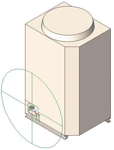
A wide range of detailed product information is available for our range. To access this information, discuss with your Fujitsu representative.
Features
• Product News
• Brochures
• Design & Technical Manuals
• Installation Manuals
• Operation Manuals
Technical support is provided at every stage from design to installation to assist in providing the most suitable air conditioning solution.
Features
• CFD Simulation
• Commissioning Support
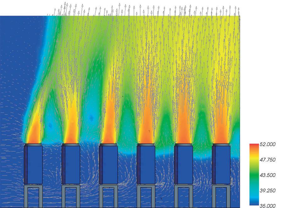
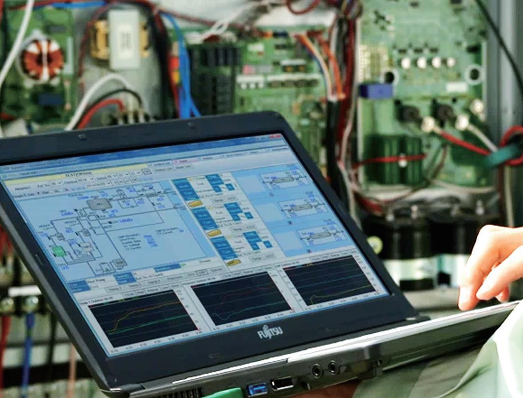

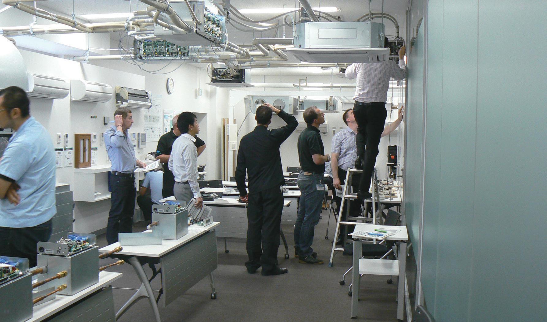
Fujitsu General has many training facilities around the world that regularly conduct specialised product, technical, and service training.
These research facilities also support the development of people to ensure high technical capability.
Features
• Designing AIRSTAGE™ Systems
• Control systems on-site training

1 Head Office Training Center: Japan
2 China Training Center: China
3 Asia Training Center: Singapore
4 Europe Training Center: U.K.
5 Europe Training Center: Germany
6 America Training Center: U.S.A.
7 Middle East Training Center: UAE
8 Oceania Training Center: Australia
Put the charts and pens away and design your projects on your computer with ease using the Design Simulator. Everything from selecting indoor and outdoor units, allocating controls and optional parts to designing the piping and wiring systems is made easier using the program’s built-in features.
Once your project is designed, take advantage of the Export functions to easily get materials lists, product specifications, refrigerant calculations and more. You can even export to Word, Excel, or Acrobat formats and group the relevant CAD data for your project.
Automatically create model selection information
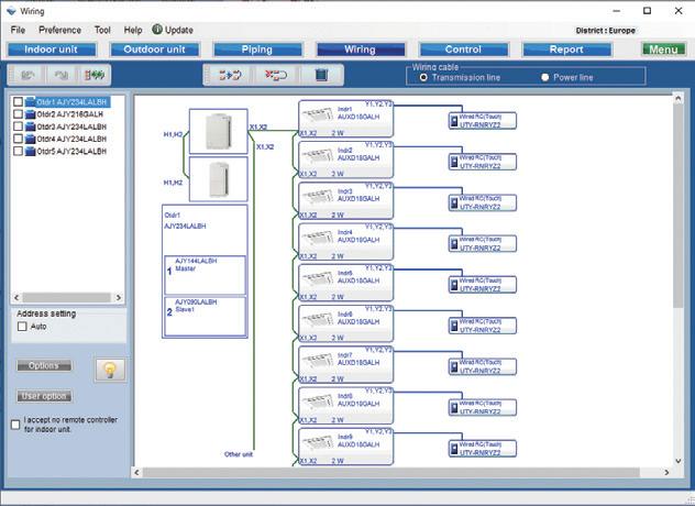
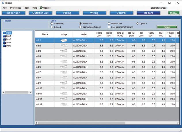
• Each unit can be automatically set by entering the required performance, type, and temperature conditions for each indoor unit, and then dragging and dropping into the outdoor unit.
• Piping and wiring diagrams can be created automatically and it is easy to set branches, grouping and options.
• Additional refrigerant charging amount is automatically calculated when pipe length is entered
• Easy to set the remote controller groups, central controller and converters.
• Equipment list including the equipment information is created automatically

Output the format that matches the application
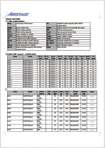
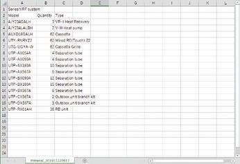
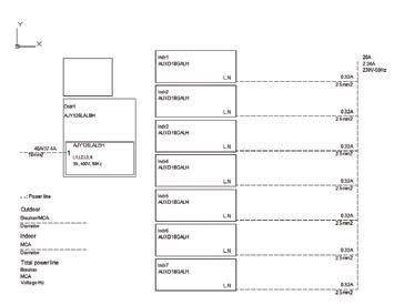
The information specific to your project can be exported in a number of industry standard file formats:
• Word format (rtf)(doc)
• Excel format (csv)
• Acrobat format (pdf)
• Auto CAD format (DXF)
• 2D Data (DXF)
• 3D Data (RFA )
The database can be easily updated online using the Auto Update function via FTP.
Information on the latest history update is demanded.


Fujitsu General has released BIM files of our products now available on BIMobject®’s website (BIMobject.com).
BIMobject® is a game changer for the construction industry, offering development, maintenance, and syndication of objects on the world’s biggest BIM platform.
• BIM files are Autodesk Revit 2018 version.
• Each of the BIM files has different refrigerant and drain piping connector location
• Each of the BIM files includes several family types.
• Revit file type catalog (Specification) is available for each product

RFA (Revit data)
Data content
• Shape (Size)
• Drain direction
• Piping direction
• Power source location
• Specifications


Using the search bar from the main homepage, key in the brand name FUJITSU GENERAL to browse the products

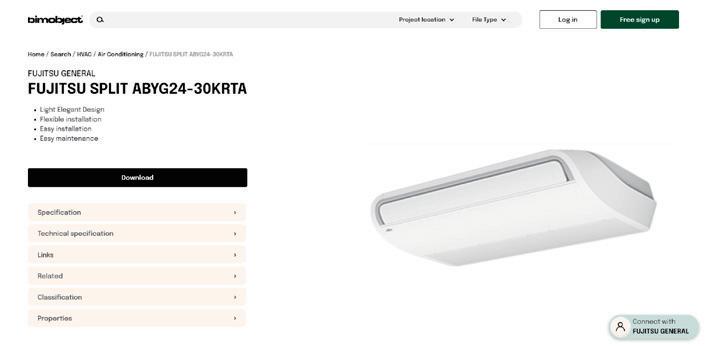

Data format available for BIM-designed projects DWG
Standard data available for Autodesk’s products
Type catalog (specifications of product) *How to use BIM files: please refer to Instructional video on each product page. youtu.be/wfL-hwFQ7dM


DXF
Intermediate data generally available for CAD products
Data content
• Shape (Size)

If an error should occur on a unit or system, there is an abundance of support tools such as trouble code display on the product.
The VRF Service Tool allows checking of the detailed status for the entire system, and a remote monitoring tool accessible via internet connection, allowing for quicker service, support and maintenance anywhere and at any time.
The air conditioner operating status and trouble status are viewable on the 7 segment display of the outdoor unit PCB or on the remote controller screen. The unit status can be checked efficiently enabling a quick response.
• Operation mode status
• Discharge temperature / Pressure status
• Compressor operation indication
• Address / Type / Number of outdoor units
• Error code

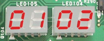
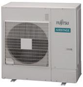
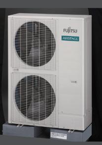
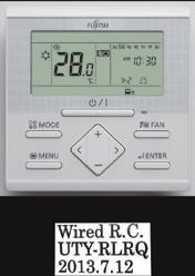
The unit status details for the VRF System can be checked on a PC screen by connecting to the Service Tool.
A quick analysis can be made. Viewable parameters include:
• Operation status / control
• Monitoring operating condition
• Monitoring sensor data
• Indication of trend graph
• Error history
• Indication of refrigerant circuit diagram
• Automatic operation check for refrigeration cycle
VRF System operating status and error status details can be constantly monitored over the Internet.
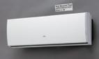


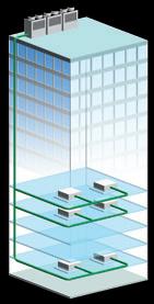
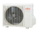
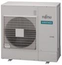

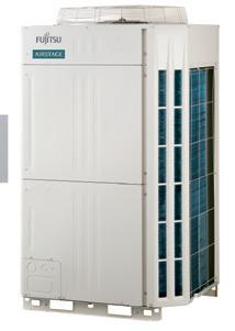
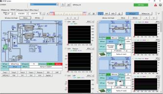

The smartphone app for troubleshooting Fujitsu General air conditioners, helps you remotely monitor the condition of your Fujitsu General system. This application is a troubleshooting tool applicable to RAC, PAC, VRF and ATW systems.
It helps you to easily check the condition of your unit. Error code check, Troubleshooting, and Sensor checks are available.
/ Apple Android/ Google


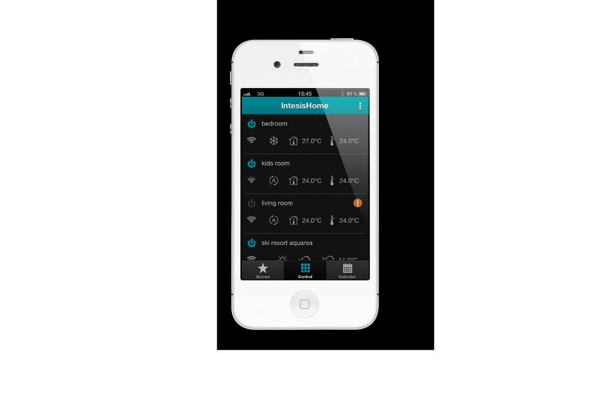
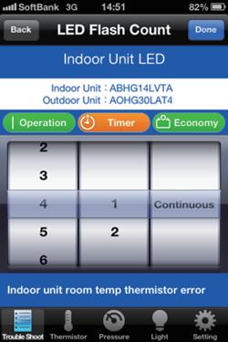
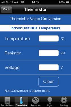
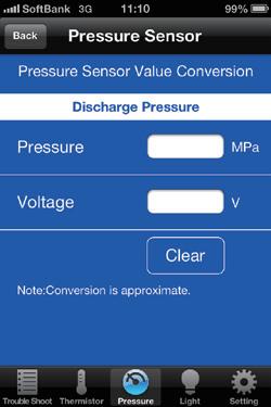
• A quick overview of the temperature sensor readings and the electronic expansion valves (EEVs), fans, compressors and other control components
• Easily read temperature sensor & status control components
• Visualizes protected operations
• Troubleshoots intermittent problems effectively
• Provides proof of normal operation to customers during periodical maintenance
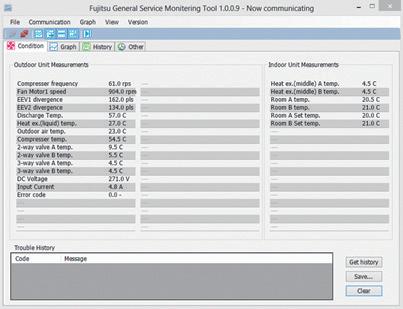
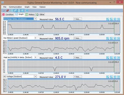
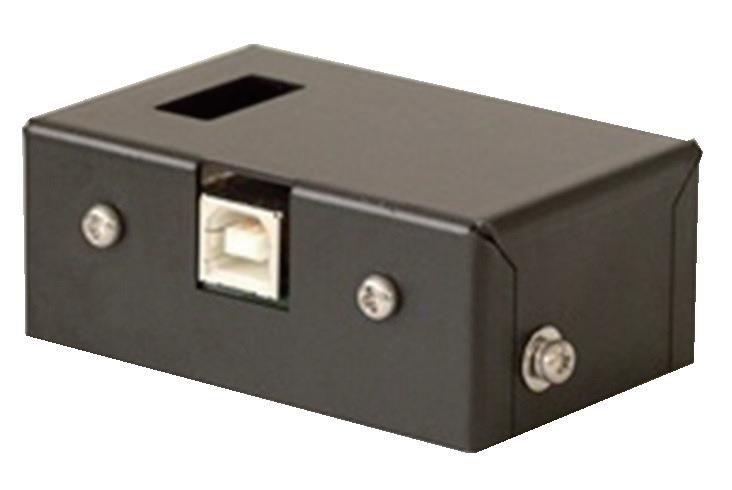
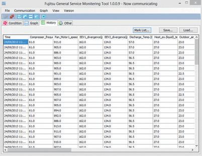
• Operation status can be checked and analysed to detect even the smallest abnormalities
• Service Tool can be used to log system operation for further analysis off-site
• Monitor up to 400 indoor units (a single VRF network system) can be controlled and monitored for large scale buildings or hotels
• Software can be connected to any point of transmission line with USB adaptor (locally purchased)
* The saved data can be displayed offline. However, the data saved by the following model cannot be displayed.
• UTR-YSTB / UTR-YSTC (Service Tool)
• UTR-YMSA (Web Monitoring Tool)
After product installation, an operation check can be performed automatically. Self diagnosis functionality automatically judges whether each sensor value is normal, saving time and workload. The diagnosis can also be output as a report.

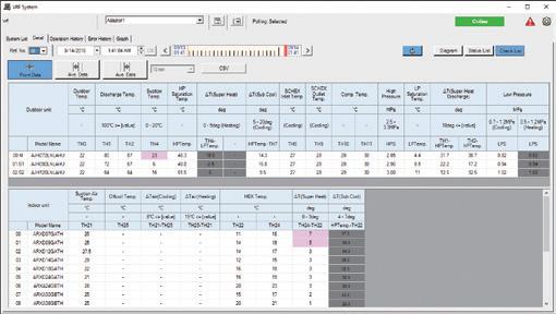
Note : Use only as a guide
On site the service tool’s screen can be shared with support personnel in a remote location. When visiting a site for troubleshooting, operation status can be shared in real-time making assistance easy. The online chat function helps to support on site staff.
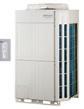

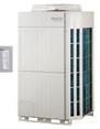
PC System Requirements
• Microsoft® Windows® 7 Professional (32-bit or 64-bit) SP1
Whether each sensor value is normal is judged automatically.
Discharge temperature normal value
Super heat volume normal value OK
High pressure pipe normal value OK
Low pressure pipe normal value OK etc.
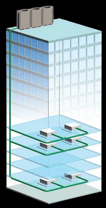

Previously, only 3 graphs could be viewed simultaneously, now multiple graphs can be displayed on the new Service Tool depending on the requirements.
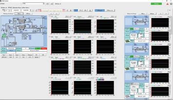
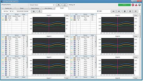
Operating system
• Microsoft® Windows® 8.1 Pro (32-bit or 64-bit)
• Microsoft® Windows® 10 Pro (32-bit or 64-bit)
CPU 1 GHz or higher
Memory
• 1 GB or more (for Windows® 7 [32-bit], Windows® 8.1 [32-bit], and Windows® 10 [32-bit])
• 2 GB or more (for Windows® 7 [64-bit], Windows® 8.1 [64-bit], and Windows® 10 [64-bit])
HDD 40 GB or more of free space
Display 1366 x 768 or higher resolution
Interface
• 2 USB ports
- 1 USB port is required for software protection key connection
- 1 USB port is required for Echelon® U10 USB Network Interface
Software Internet Explorer® 11 or Microsoft Edge / Adobe® Reader 9.0 or later
•Echelon® U10 USB Network Interface – TP / FT-10 Channel (Model number: 75010R) (Required for each VRF Network.) NOTE: Echelon adapter is sold separately.
<PACKING LIST>
Name and shape Quantity Application
WHITE-USB-KEY
(Software protection key)
1 Software protection key to be connected to USB port on the Service Tool-installed PC. These products run only on a PC with WibuKey.
•Personal computer that satisfies the following system requirements
• Troubleshooting is performed by monitoring each air conditioning unit remotely during periodical system checks
• Error notification can be automatically transmitted to several locations using the internet * 1
• Requires either a dedicated internet connection or public telephone line
• Identification of an error is possible via error warnings and equipment status information obtained from a remote location
• The system data can be downloaded remotely. This data can be viewed in the offline mode of the service tool
• The PC being used to monitor equipment isn’t required to install special software as access is via a general web browser *1: Use of internet mail system required.


• USB adaptor (maximum 4 adapters per PC) permitted
• Monitoring of up to 1,600 indoor units
• Suitable for large scale buildings or hotels
Network System Side


Monitoring Tool
adapter (Locally purchased)
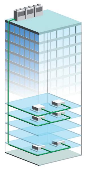
PC System Requirements UTY-AMGXZ1
Operating system
• Microsoft® Windows® 7 Professional (32-bit or 64-bit) SP1
• Microsoft® Windows® 8.1 Pro (32-bit or 64-bit)
• Microsoft® Windows® 10 Pro (32-bit or 64-bit)
CPU 1 GHz or higher
Memory
• 1 GB or more (for Windows® 7 [32-bit], Windows® 8.1 [32-bit], and Windows® 10 [32-bit])
• 2 GB or more (for Windows® 7 [64-bit], Windows® 8.1 [64-bit], and Windows® 10 [64-bit])
HDD 40 GB or more of free space
Display 1366 x 768 or higher resolution
Interface
• 2 USB ports - 1 USB port is required for software protection key connection - 1 USB port is required for Echelon® U10 USB Network Interface per
Up to 4 Echelon adapters may be required if there are multiple VRF Wiring networks on site. 1 x Echelon adapter per wiring network,
4 x wiring networks.
Software Internet Explorer® 11 or Microsoft Edge / Adobe® Reader 9.0 or later
•Echelon® U10 USB Network Interface – TP / FT-10 Channel (Model number: 75010R) (Required for each VRF Network.) NOTE: Echelon adapters are sold separately.
<PACKING LIST>
Name and shape Quantity Application
WHITE-USB-KEY
(Software protection key)
1 Software protection key to be connected to USB port on the Service Tool-installed PC. These products run only on a PC with WibuKey.
•Personal computer that satisfies the following system requirements
FUJITSU GENERAL NEW ZEALAND LIMITED
A Subsidiary of FUJITSU GENERAL LIMITED www.fujitsugeneral.co.nz
HEAD OFFICE WELLINGTON
109 Port Road, Seaview, Wellington 5010
TEl: 04 5688 761
Email contact@fujitsugeneral.co.nz


• Specifications and design are subject to change without notice for future improvement.
• The products or equipments in this catalogue contain fluorinated greenhouse gases.
• “ ” is a worldwide trademark of FUJITSU GENERAL LIMITED and is a registered trademark in Japan and other countries or areas.
• Other company and product names mentioned herein may be registered trademarks, trademarks or trade names of their respective owners.
• Actual products’ colors may be different from the colors shown in this printed material.
• iPhone and iPod touch are trademarks of Apple Inc., registered in the United States and other countries.
• “Microsoft,” “Windows,” and “Direct X” are trademarks of Microsoft Corporation in the United States and other countries.
• “Android” is a trademark of Google LLC.


Variable Refrigerant Flow System
HEAT PUMP & HEAT RECOVERY