
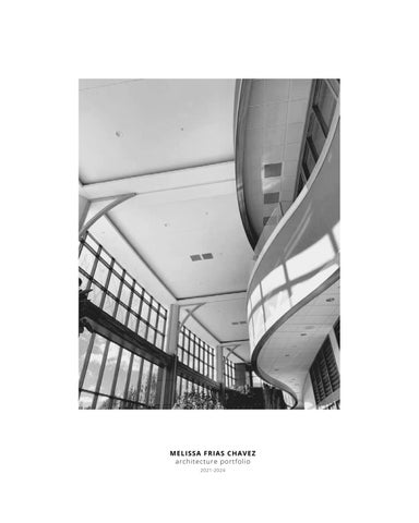
architecture portfolio 2021-2024
MELISSA FRIAS CHAVEZ


“COASTAL
architecture portfolio 2021-2024
“COASTAL
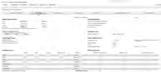
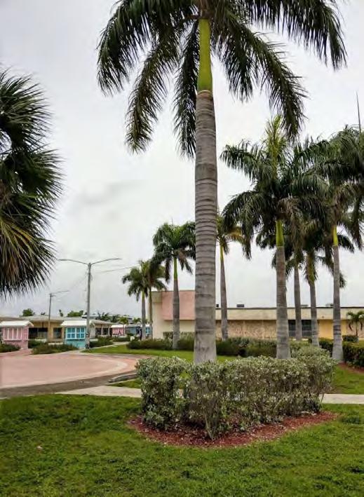
SITE: #5 Jireh Plaza Freeport Grand Bahama, Bahamas
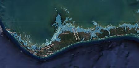
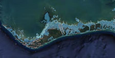
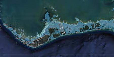
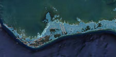
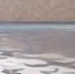
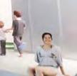
The Bahamas is increasingly vulnerable to environmental challenges like sea-level rise and natural disasters, exemplified by Hurricane Dorian in 2019. These threats underscore the urgent need for resilient infrastructure to safeguard public health and community well-being.
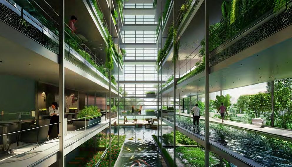
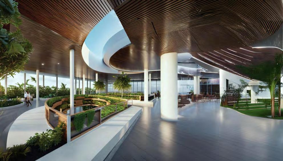
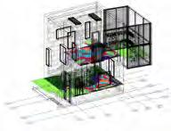
In response, a stilt-based clinic has been designed to withstand flooding and provide essential healthcare services. Elevated 9.5 meters above ground, it includes private patient rooms with natural ventilation, smart glass for energy efficiency, and wooden louvers for passive cooling. Solar-powered algae tubes ensure sustainability, while the rooftop fosters education and community engagement with sustainable food practices. A vertiport facilitates emergency rescues with rapid response capabilities. By combining advanced technology, sustainable design, and resilience, this clinic serves as a model for addressing climate challenges. It showcases how thoughtful design can protect vulnerable communities, ensuring health, safety, and sustainability in the face of escalating environmental threats.
2060
Studio
ARC 6970- Masters Project
Professors
Thomas Spiegelhalter
Semester
Spring 2024
Software
Autodesk Revit
Rhinoceros 7
Adobe Illustrator
Adobe Photoshop
Midjourney
Autodesk Veras
Green Building Studio
Microsoft Excel
Images
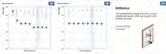
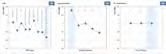
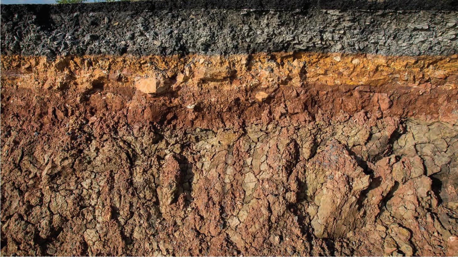
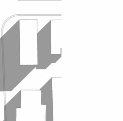
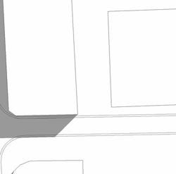
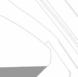
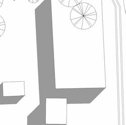
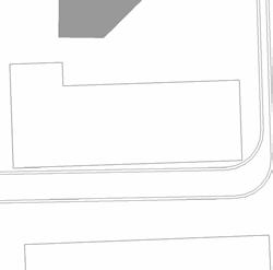
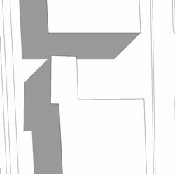
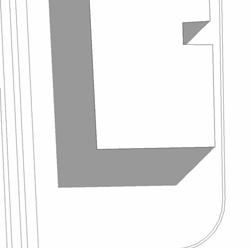
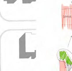
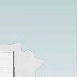
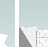
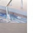
a.1-a.4 : The Bahamas sea level rise + major flood scenarios in the years: 2030, 2060, 2080, 2100
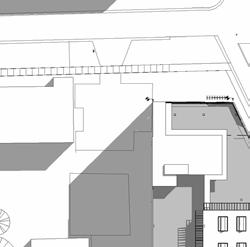
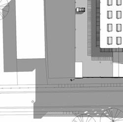
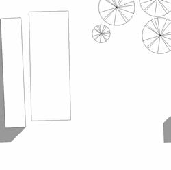
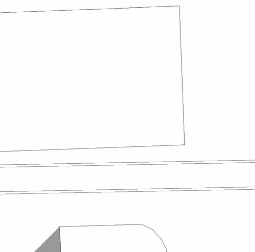
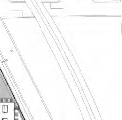
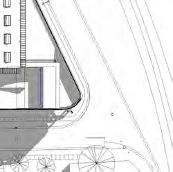
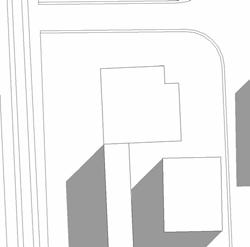
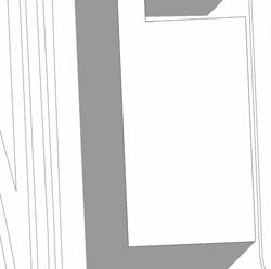
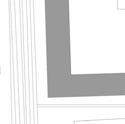
a.5 : site plan
Year 2100 Site Scenario AmphibiousTransportation
Site Elevation: 4 MASL


‘Great Miami’ CAT 4 1926
Pharmacy
Doctor’s Office
Pharmacy’s Storage
Treatment Room
X-ray/CT Room
Supply Room
Dress Room
Recovery Room
Operating Room
Medical Records Room
Laboratory
Nurse’s Area
Storage
MEP
Reception
Specialty Room


Cafeteria
Doctor’s Office
Examination Room
Nurse’s Area
X-ray/CT Room
Procedure Room
Isolation Room
ER Treatment Room
Medical Records Room
Reception
Triage Room
Laboratory
Lab Waiting Room
MEP
Consultation Room


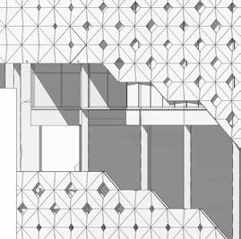
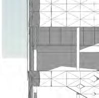
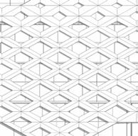
a.6-a.7 : axonometric clinic floor plans
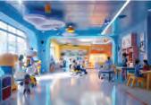
a.8-a.9 : axonometric daycare floor plan + axonometric administrative floor plan
Locker
Weight
Parents
Assembly
Medical
Nurse’s
Infant’s
Consultation


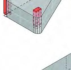
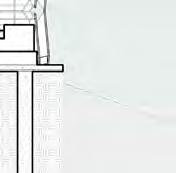
1. 14X102 CARBON-NEUTRAL STEEL IBEAM
2. ANCHOR BOLTS
3. STEEL ANGLE
4. 14X102 CARBON-NEUTRAL STEEL IBEAM- WELDED TO COLUMN
5. 14X0.500 ANGLED CARBON NEUTRAL HSS ROUND HOLLOW STRUCTURAL
SECTION COLUMN
1. DOUBLE GLAZED PANEL
2. VERTICAL MULLION
3. HORIZONTAL MULLION
4. GRAVEL BUFFER
5. FILTER LAYER
6. DRAINAGE LAYER
7. MOISTURE RETENTION MATT
8. WATERPROOF MEMBRANE
9. 150MM CONCRETE FLOOR
10. 200MM CONCRETE WALL
11. 14X102 CARBON-NEUTRAL STEEL I-BEAM
12. STEEL ANGLE
13. ANCHOR BOLTS
14. FLASHING
15. WOOD STUDS (STRUCTURAL)
16. SCUPPER
17. GUTTER
18. STEEL ANGLE SCREWED TO STRUCTURE
19. 80MM RIGID INSULATION
20. AIR GAP-STRUCTURE
21. EXTERIOR CLADDING
1. VERTICAL MULLION
2. DOUBLE GLAZED PANEL
3. 40.7CMX40.7CMX5.5.1CM MYCELIUM INTERIOR PANELS
4. RIGID INSULATION
5. WATERPROOF MEMBRANE
6. 200MM CONCRETE WALL
7. WALL SEALANT
8. 50MM ACOUSTIC INSULATION
9. WATERPROOF MEMBRANE
10. 80MM SCREED (CONCRETE+SAND)
11. THERMOACTIVE FLOORING FLOOR FOR HEATING AND COOLING
12. SCHOCK ISOCORB FOR THERMAL BREAK
13. 200MM CONCRETE WALL
14. SANITARY SEALANT
15. 2.5MM X 7.5M ALTRO WHITEROCK CLADDING PANELS
1. 120MM EARTH LAYER
2. GRAVEL BUFFER
3. DRAINAGE LAYER
4. MOISTURE RETENTION MATT
5. 80MM RIGID INSULATION
6. 200MM CYANOBACTERIA CONCRETE WALL
7. 2540MMX 2540MM ALUCOBOND PANELS
8. SEALANT
9. 50MM ACOUSTIC INSULATION
10. 80MM SCREED (CONCRETE+ SAND)
11. THERMOACTIVE FLOORING FLOOR FOR HEATING AND COOLING
12. 25.4MM CERAMIC FLOORING TILES
13. 150MM CONCRETE FLOOR SLAB
Images
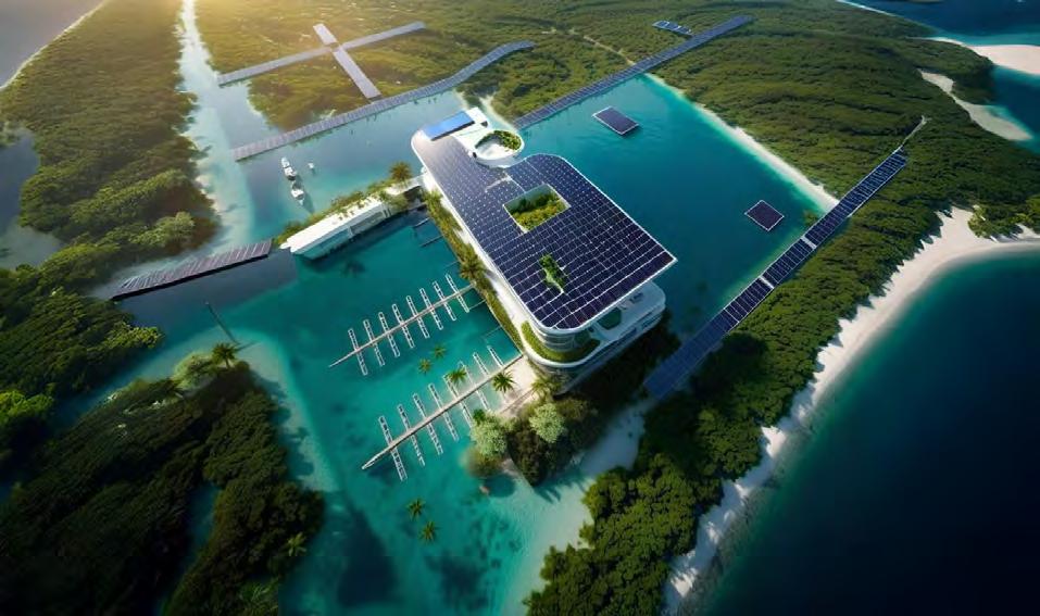
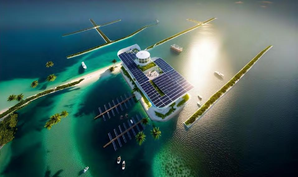
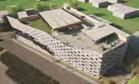
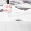
a.10-a.11 : render drone view of site in the year 2080 & 2100
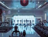
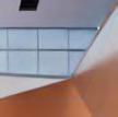
a.12-a.13 : vertical garden interior view & rooftop view
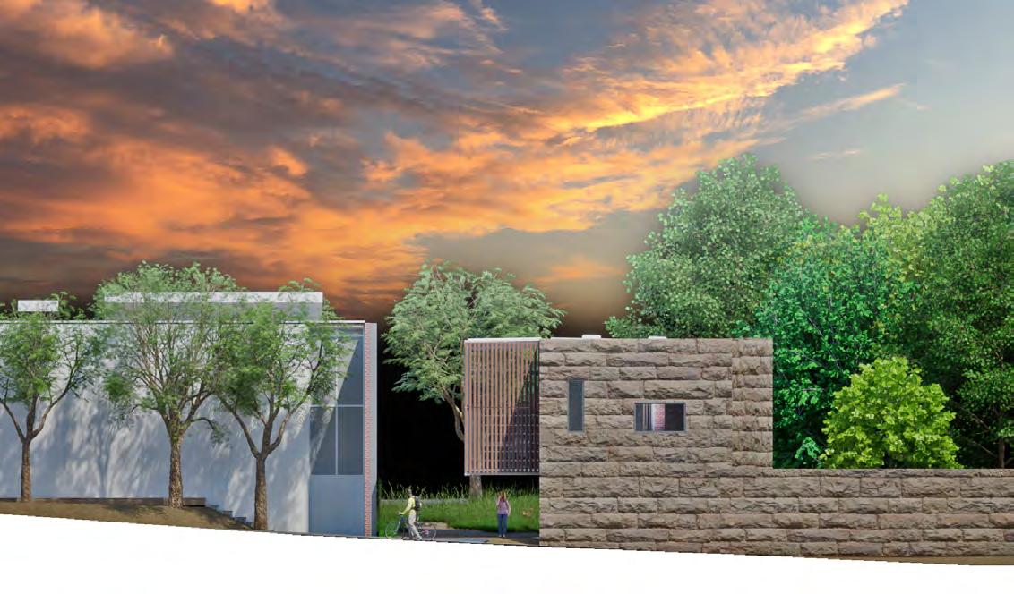
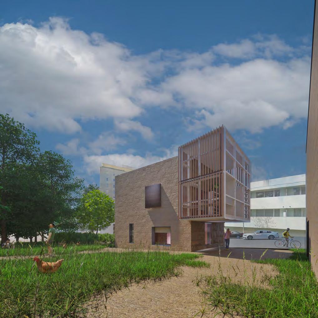
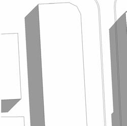
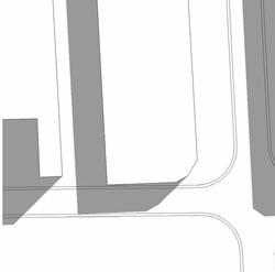
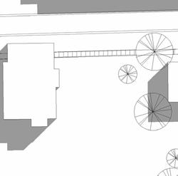
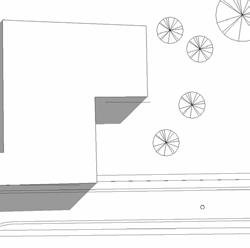
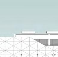
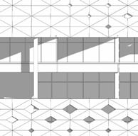
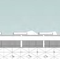
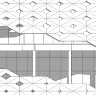
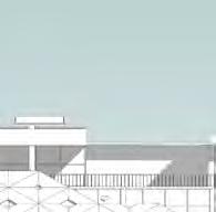
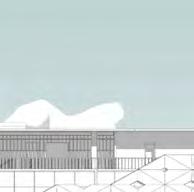
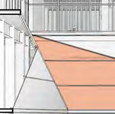
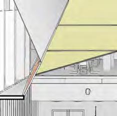
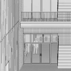
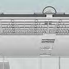
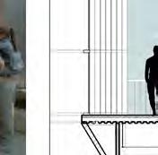
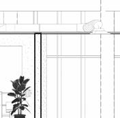
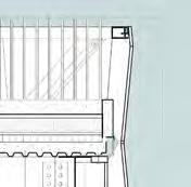
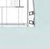
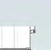
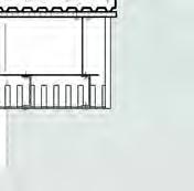
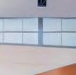
The fundamental idea behind the project was to design a single-family residence for a museum guard located adjacent to the prominent “Casa das Artes” museum in Portugal. Limestone was selected as the primary building material, mirroring the architectural materials of the surrounding structures. The limestone walls delineate the private areas, comprising the kitchen, bathroom, and bedroom.
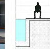
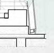
Elevating the design, a second-floor glass box is affixed to the wall, creating a cantilever that serves as both an office space and an overlook point for the guard within the residence. This glass enclosure strategically aligns with the existing walls, mimicking their angles to minimize disruption to the site. In addition, the glass box is intentionally shifted to the right, optimizing the guard’s view of the garden from within.
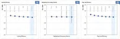
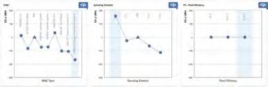
The architectural configuration incorporates passive systems to mitigate the impact of harsh sunlight, demonstrating a commitment to both functional comfort and aesthetic cohesion. Overall, the residence harmoniously integrates with its surroundings, paying heed to the site’s existing geometry while providing the museum guard with a purposeful and aesthetically pleasing living space.


Studio
ARC 6356- Design 10
Professors
Jason Chandler & Thomas
Spiegelhalter
Semester
Summer 2023
Software
Autodesk Revit
Rhinoceros 7
Twinmotion
Adobe Illustrator
Adobe Photoshop
Green Building Studio
ARCGIS
Insight 360
Images
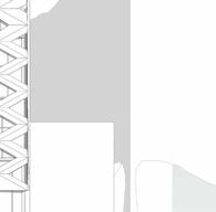
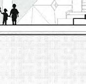
a.1-a.3 : east, south, north
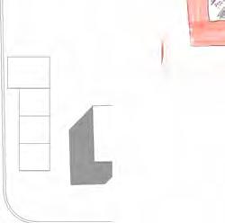
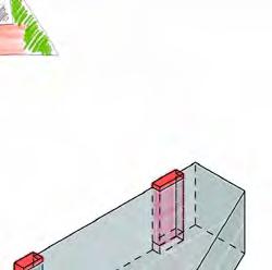
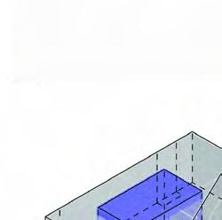
a.4 : worm’s eye axonometry


4.
5. 3MM SARNAFIL ROOFING WATERPROOF
6. 50MM ROOFING CLAY TILE
7. 100MM RIGID INSULATION U Value= 0.80 W(m2k)
LEGEND:
LEGEND:
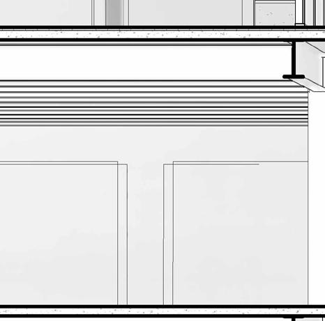
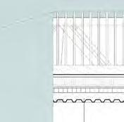
ROOF:
ROOF:
1. GUTTER
1. GUTTER
2. PHOTOVOLTAIC HYBRID THERMAL SOLAR PANELS
2. PHOTOVOLTAIC HYBRID THERMAL SOLAR
PANELS
3. PV ANCHOR BOLT
3. PV ANCHOR BOLT
4. AIR GAP
4. AIR GAP
5. 3MM SARNAFIL ROOFING WATERPROOF MEMBRANE
5. 3MM SARNAFIL ROOFING WATERPROOF MEMBRANE
6. 50MM ROOFING CLAY TILE
6. 50MM ROOFING CLAY TILE
7. 100MM RIGID INSULATION U Value= 0.80 W(m2k)
7. 100MM RIGID INSULATION
U Value= 0.80 W(m2k)
8. WATERPROOF MEMBRANE
8. WATERPROOF MEMBRANE
9. 205MM CONCRETE SLAB
9. 205MM CONCRETE SLAB
10. 13MM THICK GYPSUM BOARD
10. 13MM THICK GYPSUM BOARD
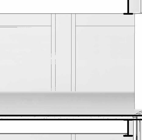
UPPER WALL:
UPPER WALL:
11. 30MM THICK WOOD DOOR
11. 30MM THICK WOOD DOOR
12. INTERIOR WALL
12. INTERIOR WALL
13. WINDOW MULLION
13. WINDOW MULLION
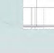
FLOOR:
FLOOR:
14. 12.5 MM THICK WOOD FLOORING
14. 12.5 MM THICK WOOD FLOORING
15.THERMOACTIVE FLOORING FLOOR FOR COOLING AND HEATING
15.THERMOACTIVE FLOORING FLOOR FOR COOLING AND HEATING
16. 80MM SCREED (SAND+CEMENT FIBERS)
16. 80MM SCREED (SAND+CEMENT FIBERS)
17. WATERPROOF MEMBRANE
17. WATERPROOF MEMBRANE
18. 50MM ACOUSTIC INSULATION
18. 50MM ACOUSTIC INSULATION
19.150 MM CONCRETE SLAB
19.150 MM CONCRETE SLAB
20. 80MM RIGID INSULATION
20. 80MM RIGID INSULATION
21. 12.5MM STUCCO LAYER
21. 12.5MM STUCCO LAYER
22. 8MM FOAM EDGE INSULATION
22. 8MM FOAM EDGE INSULATION
CURTAIN WALL:
CURTAIN WALL:
23. DOUBLE GLAZING - 6MM THICKCLEAR/LOW-E (e=0.05) CLEAR GLASS
23. DOUBLE GLAZING - 6MM THICK -
CLEAR/LOW-E (e=0.05) CLEAR GLASS
24. 1OMM AIR GAP
24. 1OMM AIR GAP
25. MULLION
25. MULLION
26. BATT INSULATION LAYER
26. BATT INSULATION LAYER
27. STEEL PLATE
27. STEEL PLATE
28. ANCHOR BOLT
28. ANCHOR BOLT
29. STEEL PLATE EMBEDDED IN CONCRETE
SLAB
29. STEEL PLATE EMBEDDED IN CONCRETE
SLAB
30. FLASHING
WALL:
30. FLASHING
WALL:
31. 215X102.5X6MM BRICK LAYER
31. 215X102.5X6MM BRICK LAYER
32. 205MM CONCRETE WALL
32. 205MM CONCRETE WALL
33. 90MM RIGID INSULATION
33. 90MM RIGID INSULATION
34. WATERPROOF MEMBRANE
34. WATERPROOF MEMBRANE
35. 12.5MM AIR GAP
35. 12.5MM AIR GAP
36. 50 MM EXTERIOR NATURAL STONE LAYER
36. 50 MM EXTERIOR NATURAL STONE LAYER
37. FLASHING
37. FLASHING
U VALUES:
i- ROOF: 0.30
ii- FLOOR: 0.23
iii- WALL: 0.35


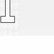
38. MOSQUITO MESH FOUNDATION
38. MOSQUITO MESH
FOUNDATION
39. WOOD STUD
39. WOOD STUD
40. WATERPROOF MEMBRANE
40. WATERPROOF MEMBRANE
41. FOUNDATION WALL
41. FOUNDATION WALL
42. 100MM DIAMETER DRAINAGE PIPE
42. 100MM DIAMETER DRAINAGE PIPE
43. GRAVEL LAYER 44. STRIP FOOTING
43. GRAVEL LAYER
44. STRIP FOOTING 2 3
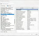
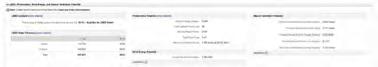
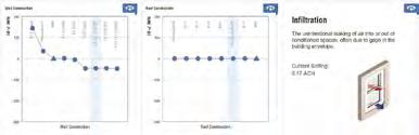
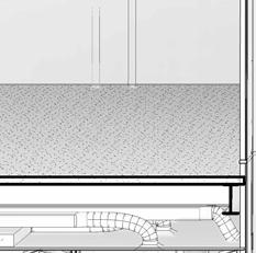
MEP SETTINGS
MEP SETTINGS
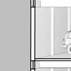
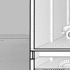
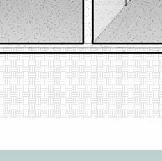
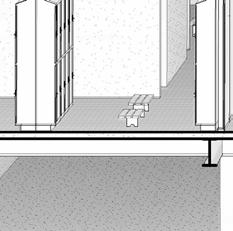
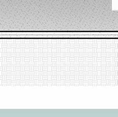
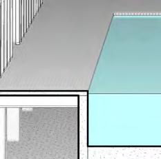
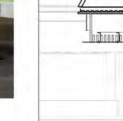
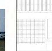
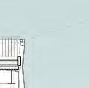
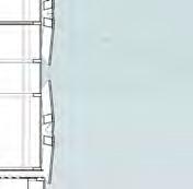
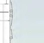
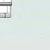
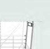
Images : roof + floor detail
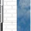
a.10 : wall + foundation detail
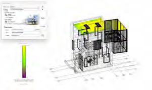


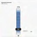
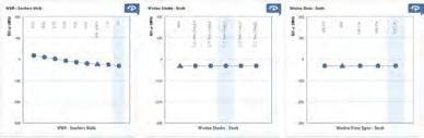
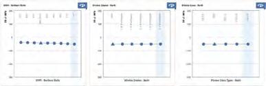
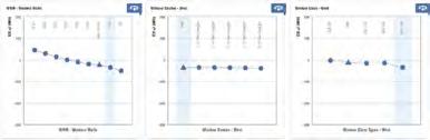
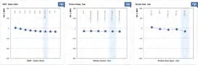
SOLAR ANALYSIS


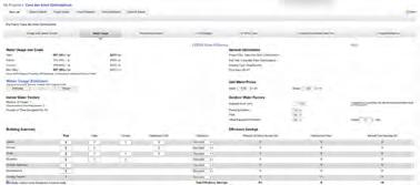
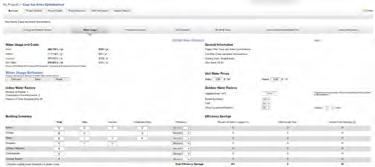


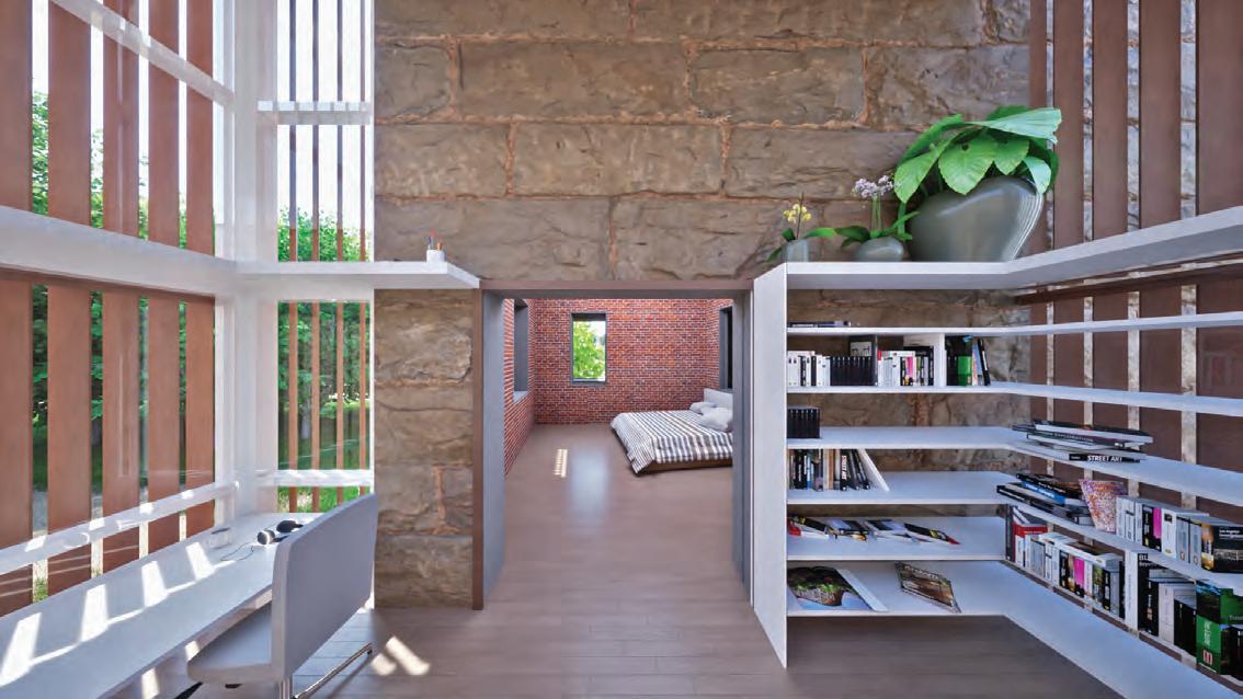
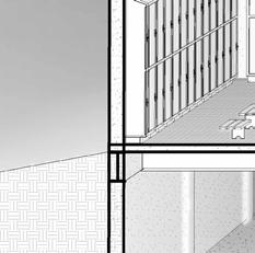
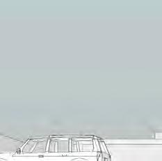
a11 : office rendering
: east elevation rendering
: exterior rendering
SITE: 390 NE 71ST ST., MIAMI, FL, 33174
D2 DISTRICT ZONE
-LEAST REGULATED BUILDING
-ACCOMMODATES COMMERCIAL AND INDUSTRIAL USES OF CERTAIN SCALE
-FLAT ROOFS SHALL BE ENCLOSED BY PARAPETS
-MAXIMUM BUILDING HEIGHT: 8 STORIES
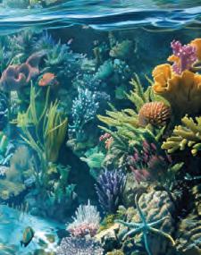
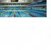
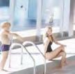
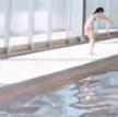
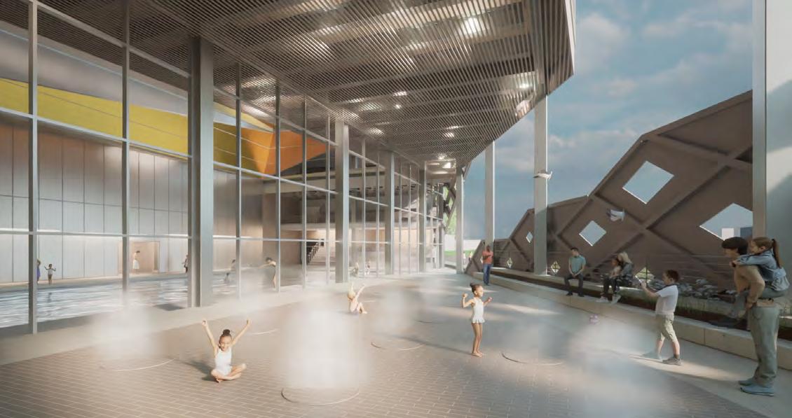
The genesis of the natatorium concept stemmed from the combination of two primary influences: a precedent case study exemplified by the Water Cube Natatorium and the Bassin Blue Waterfalls in Haiti. The focal point of this archi tectural project is a 60-foot atrium, encompassed by diverse wall compositions, emulating the immersive ambiance of a waterfall basin enclosed within a natural grotto landscape.
-OFF STREET BICYCLE PARKING SHALL BE PROVIDED -BASEMENTS MAY HAVE 1 LEVEL UNDERGROUND PARKING SPACES.
SKETCHES
Sheet 1 2 10/04/22 BUILDING
DIAGRAMS
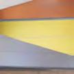
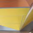
In order to instill dynamism and evoke a vibrant atmosphere within the central courtyard, walls were decorated with yellow and orange aluminum panels. These jagged formations serve the dual purpose of introducing movement and disrupting the inherent rigidity of the pool area.
AND INDUSTRIAL USES OF CERTAIN SCALE
BY PARAPETS
8 STORIES PARKING SHALL BE PROVIDED LEVEL UNDERGROUND PARKING SPACES.
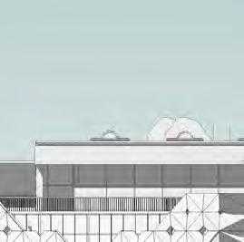
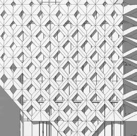
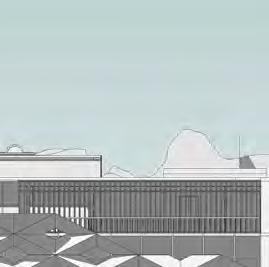
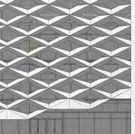
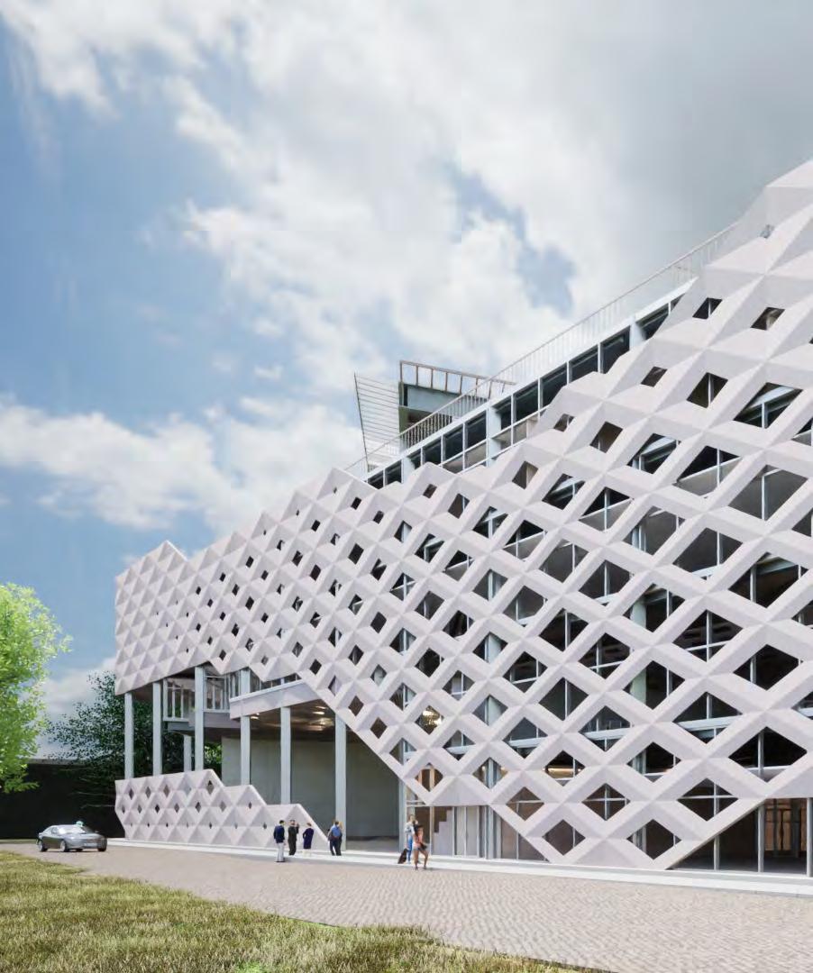
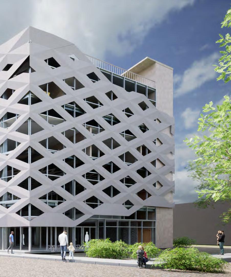
The parametric facade is constructed using glass-fiber reinforced concrete panels, affording the flexibility to be perforated in accordance with interior privacy considerations. This design choice ensures a harmonious blend of aesthetics and functionality, reflecting a meticulous approach to the creation of a compelling and engaging natatorium space.
DIAGRAMS
Studio
ARC 5361- Comprehensive
Studio
Professors
Marcelo Ertorteguy
Semester Fall 2022
Software
Autodesk Revit
Rhinoceros 7
Twinmotion
Adobe Illustrator
Adobe Photoshop
Images
a.1-a.4 : egress, void/solid, wet/dry, BOH diagram
a.5 : site plan
PRECEDENT PICTURES- INSPIRATIONAL BOARD
PRECEDENT PICTURES- INSPIRATIONAL BOARD
PRECEDENT PICTURES- INSPIRATIONAL BOARD


= 1' -0"


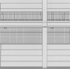
: north elevation, east elevation a.8-a.11 : ground floor plan, second floor plan, third floor plan, fourth floor plan


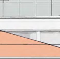
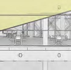
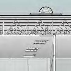
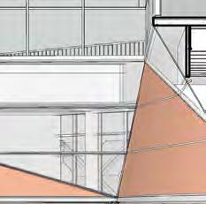

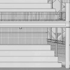
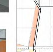
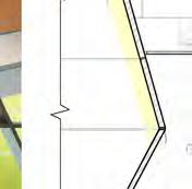
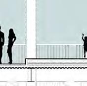
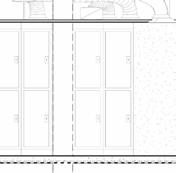
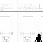
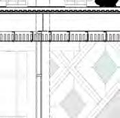
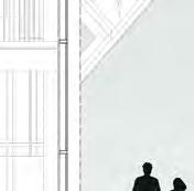
a.12 : perspective section a.13 : wall section + callouts


Images
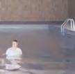
a.14-a.15 : outdoor render + interior pool render
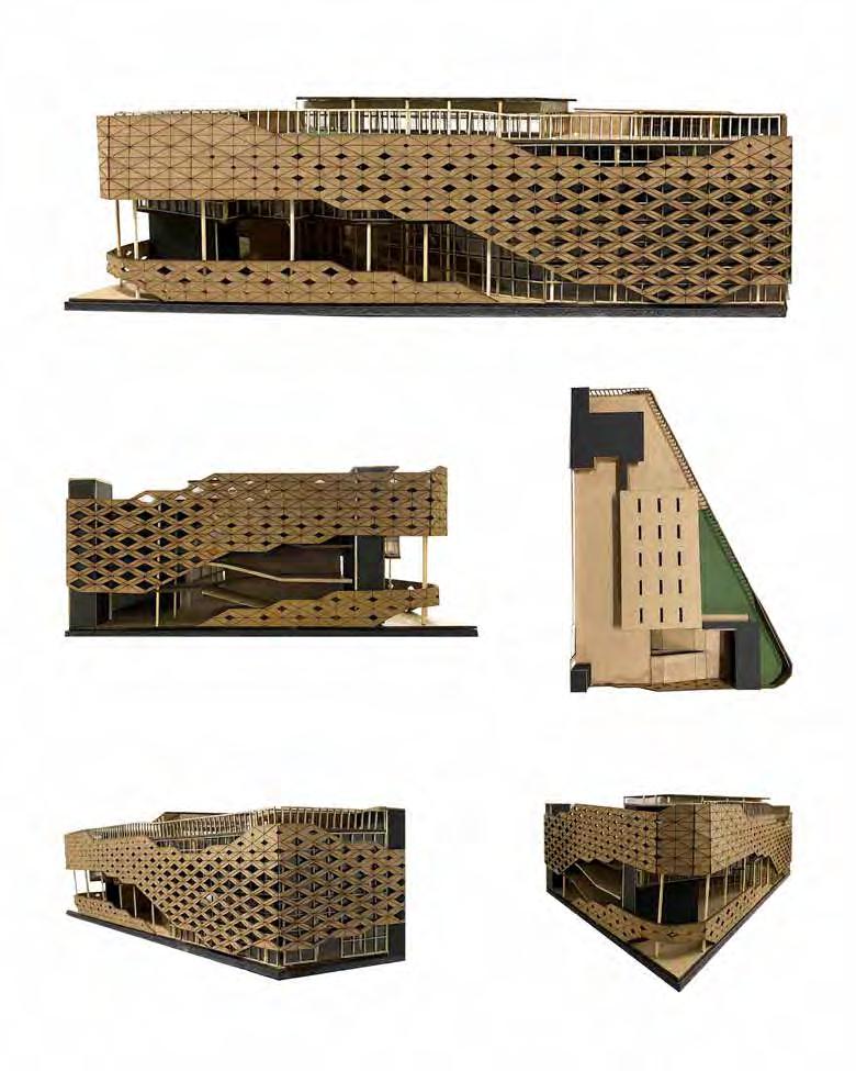
a.16-a.20 : 1/4” scale physical model
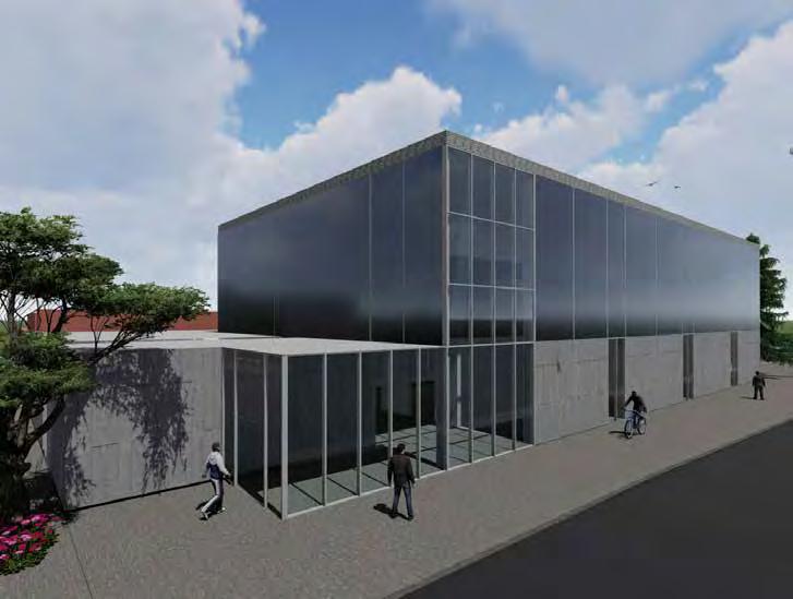
Site: 600 S. Phillips Ave. Sioux Falls, SD 57104
The over arching concept behind the architectural project was to transform a library into a gymnasium in Downtown Sioux Falls. The resultant development is characterized by a seamless fusion of contemporary design principles with the permanent features of the original structure. It is remarkable the intentional incorporation of a glass facade at the primary entrance, facilitating the penetration of natural light into the hallways and support desk areas. This strategic utilization of glass serves not only an illuminative purpose but also contributes to a nuanced spatial transition from well-lit public zones to more seclude and private areas.
The preservation of the outer shell encapsulating the inner structure reflects a discerning approach that harmonizes historical preservation with contemporary design sensibilities. The conversion of the former basketball court and mezzanine level into a designated private space further augments the multifunctional aspect of the facility.
Material selection plays a pivotal role in the architectural narrative, with concrete and steel walls comprising the predominant facade elements, ensuring structural integrity and durability.
Studio
ARCH 455- Vertical Building
Studio
Professors
Jessica Garcia-Fritz
Federico Garcia-Lammers
Brian Lee
Robert Arlt
Nesrine Mansour
Semester
Spring 2021
Software
Rhinoceros 7
Lumion
Adobe Illustrator
Adobe Photoshop
Images
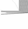
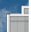
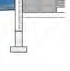
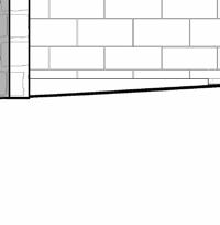
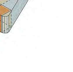
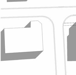
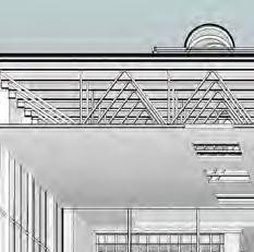
a.1-a.3 : roof, wall, foundation technical drawings
a.4 : exterior rendering


a.5-a.7 : section, elevation and ground floor plan ( library )
a.8-a.10 : section, mezzanine level and ground floor plan ( gym )


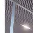
MEZZANINE JOIST
SUSPENDED CEILING TILES
Thank you