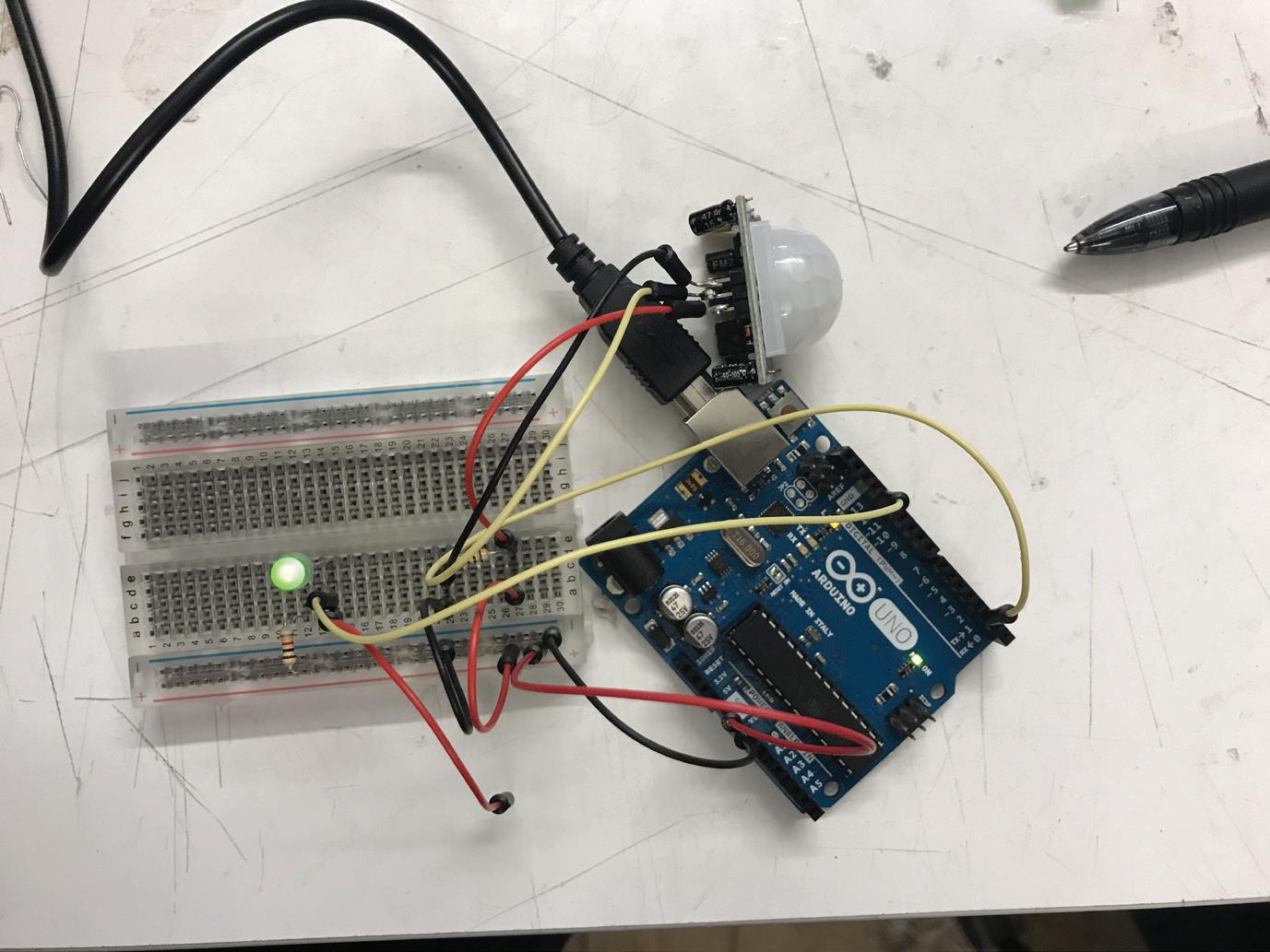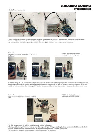
STEP1: TESTING THE PIR SENSOR
ARDUINO CODING PROCESS
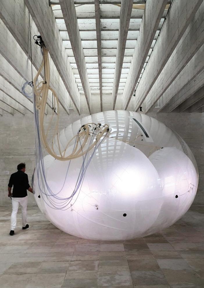
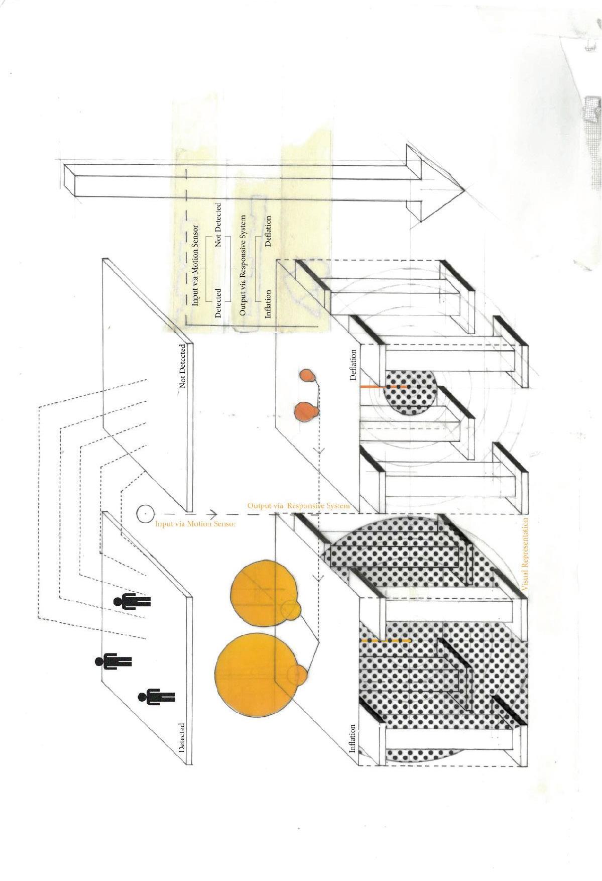
To test whether the PIR sensor worked, we created a code that would light up an LED every time movement was detected by the PIR sensor. We then coded in a time delay of 6 seconds which the light would remain turned on for. We would then aim to swap in a relay module component instead of the LED, which would control the air compressor.
STEP2: BRIDGING PIR SENSOR AND RELAY MODULE (inflation)
VIDEO : https://media.giphy.com/media/QuyqL3xh9a2xH9kpyY/giphy.gif
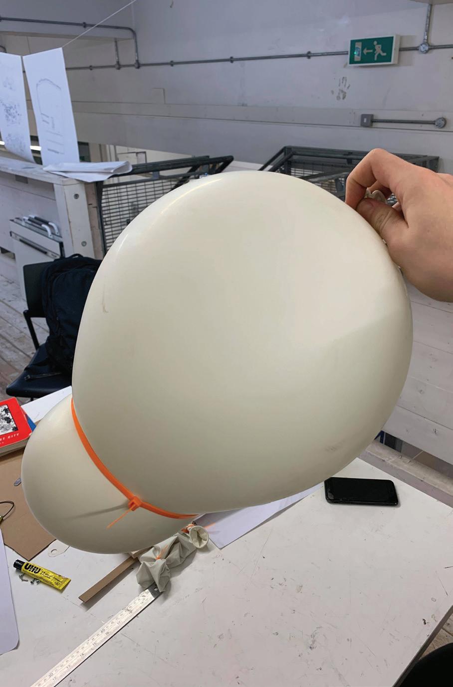
In order to change the LED component to a relay module, we had to alter the code slightly to specify the link between the PIR and relay componets. We used the same Digital pin and time delay of 6 seconds, however now when motion was detected by the PIR sensor the green light on the relay would turn on for 6 seconds before switching off. When the relay is connected to the air compressor, this would inflate the balloon for 6 seconds.
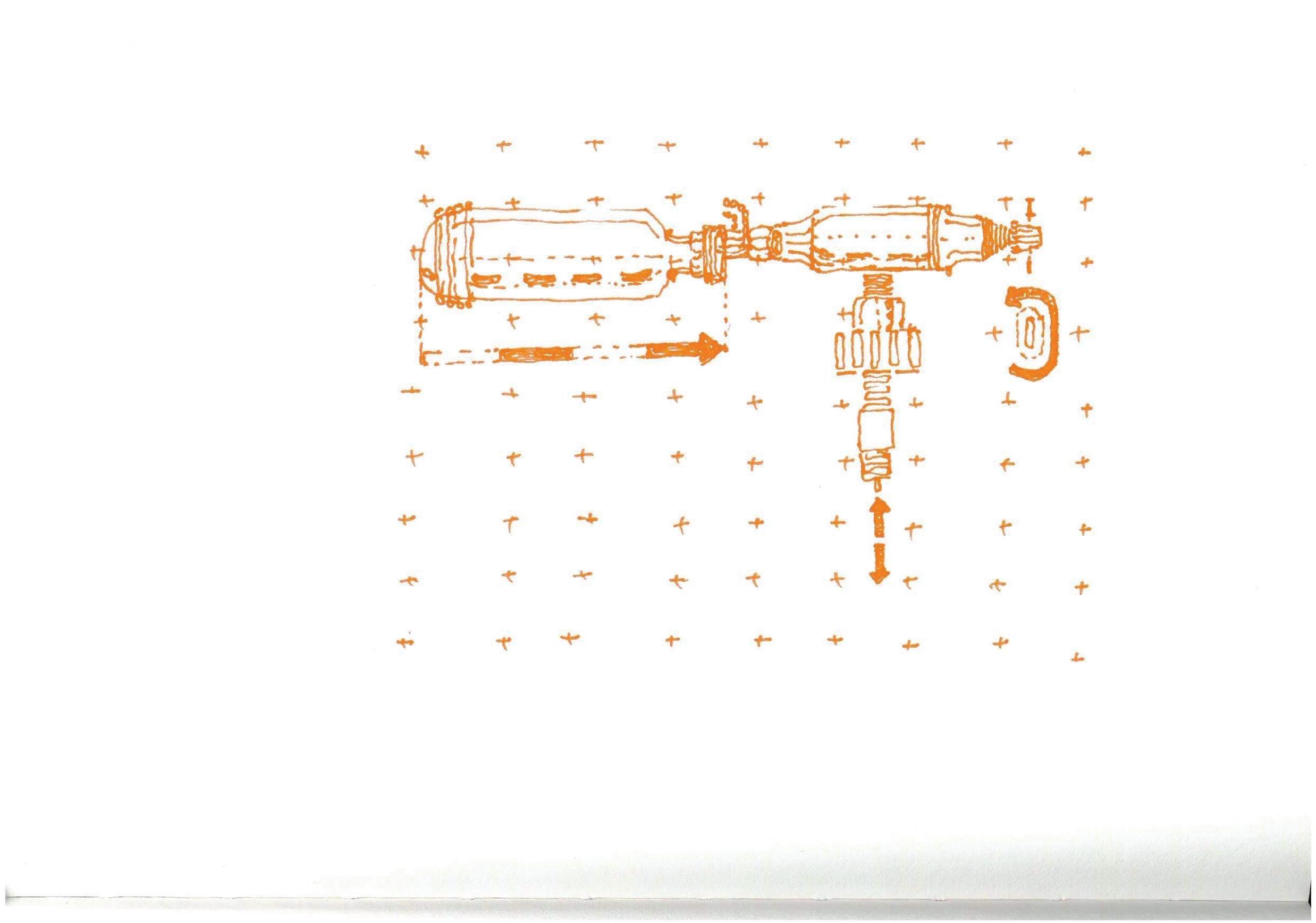
S T E P 3: BRIDGING PIR SENSOR AND SERVO-MOTOR (deflation)
VIDEO : https://media.giphy.com/media/cl7l2DquWwI5QHKqvS/giphy.gif
The final step was to code for deflation immediately after inflation had stopped. This required the coding of a linear servo component that’s cog would spin 180 degrees, pushing the linear actuator into the deflation valve for 6 seconds. Afterwhich, the cog would spin another 180 degrees, returning the linear actuator to its initial state. The entire process is ready to be repeated again if motion is detected by the PIR sensor.