
PORTFOLIO

ARCHITECTURAL TECHNOLOGIST
ABOUT ME


To be a meaningful Architect one must have a purpose behind every concept and designs. I aspire to be an Architect with great impact to the society. As a city’s economy arises, architecture must also evolve to meet the society’s need. Innova tive and creativity is what I define myself, knowing the importance of each design is a key value. I am working to be an efficient designer/ Technologist that mainly focuses on sustainable and accessible designs.
TABLE OF CONTENTS
CONCEPTUAL DESIGN: WHIRLPOOL
- Project based on concept as a proposal for University of Toronto public garden.

PROJECT # 1 RESIDENTIAL
- Floor plan blowout
- Elevations
- Construction Details
- Assembly Details/ Sectional Elevations
PROJECT # 2 INDUSTRIAL
- Floor plan blowout
- Elevations
- Construction Details
- Assembly Details/ Sectional Elevations
PROJECT # 3 COMMERCIAL PLAZA
- Floor plan blowout
- Elevations
- Construction Details
- Assembly Details/ Sectional Elevations
PROJECT # SENIOR’S HOUSING
- Floor plan blowout
- Elevations
- Construction Details
- Assembly Details/ Sectional Elevations


1
2 3 4 5
DESIGN

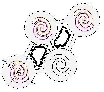
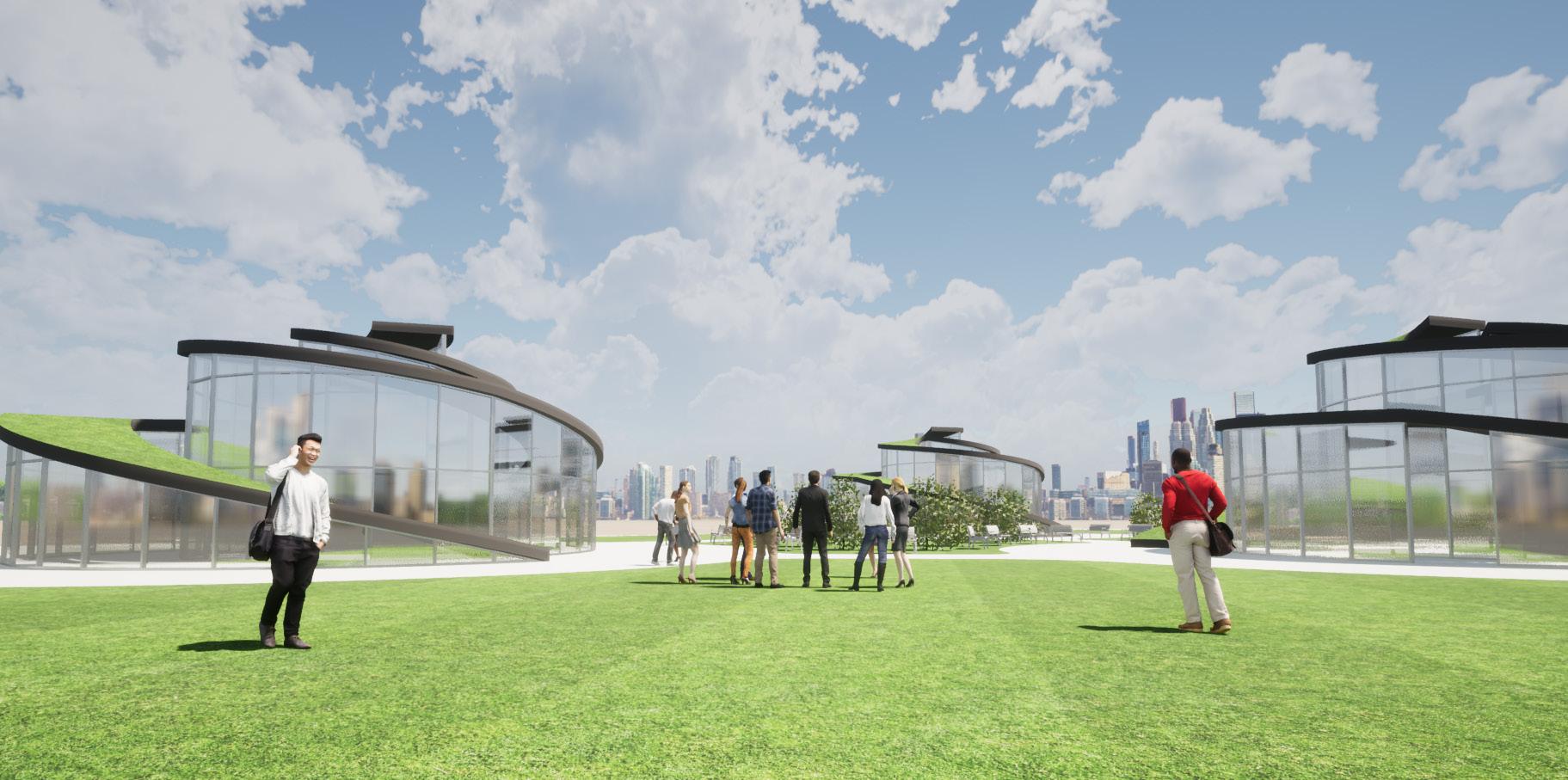
A design concept I created during my Architectural Graphics course. We are tasked to make a concept that can be use by the students and passerby at a Local area near University of toronto.
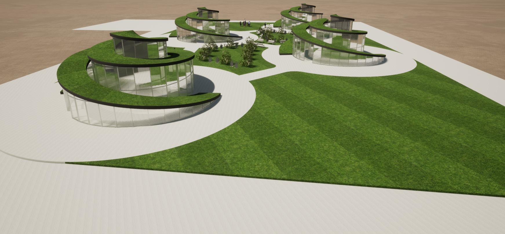
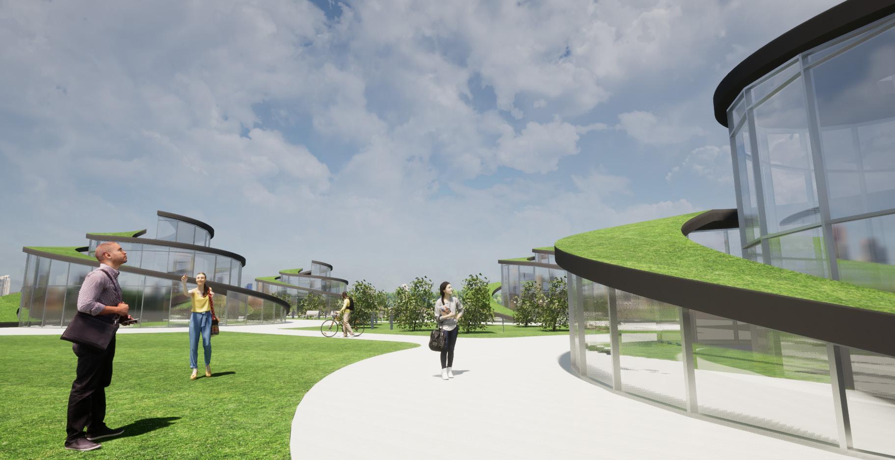
I came up with an idea of using a whirlpool concept that is composed of moslty curtain walls and a intensive roofing design. This concept idealy focused on the air ven tilation, focusing on natural airflow that comes in the struc ture.
 PLAN LAYOUT
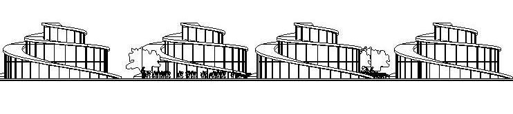
ELEVATION CONCEPT
PLAN LAYOUT
ELEVATION CONCEPT
PROJECT: 1 WHIRLPOOL
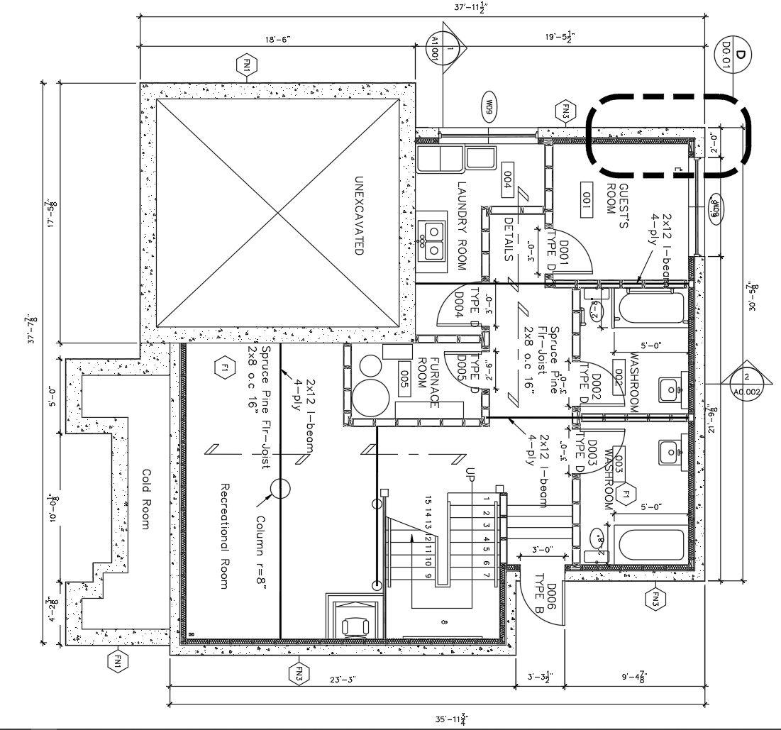
A Residential Housing project that is mainly based on sustainable and accessibility design. This project consists of one (1) ground level accessible bedroom. (2) two Second floor bedrooms, and (1) guest bedroom on the basement level. Each floor is designed to have designated washrooms.
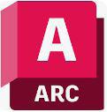
To make the project more accessible for the elderly or people with disabilites. I designed the house to have an accessible elements such as, ver tical ramps and a wheelchair lift that goes to the basement and to the second floor level.
The second feature about this project is the sustainability factor , which is the solar panels, that is capable of gathering natural sunlight and convert it into usable electricity for the house’s dai ly electrical consumption by doing so this house will have natural resources of electricity.
SECOND FLOOR PLAN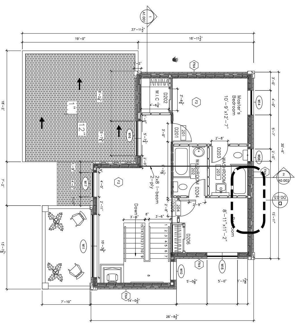

GROUND LEVEL FLOOR PLAN
SoftWare Used AutoCad PROJECT: 1 RESIDENTIAL
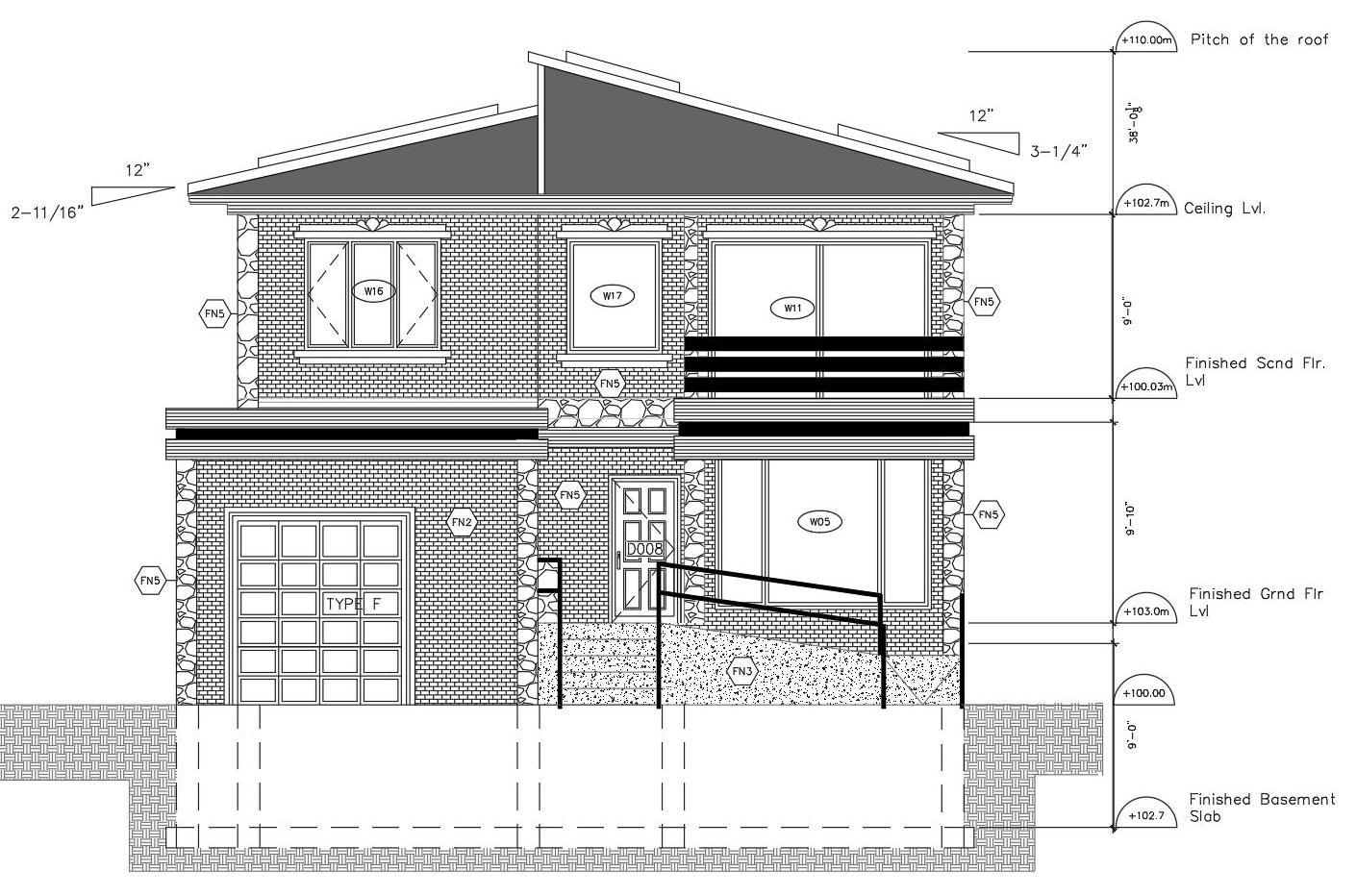
NORTH ELEVATION
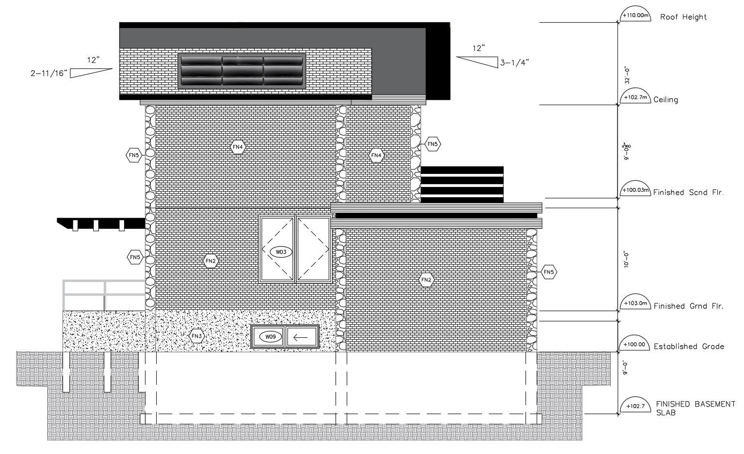
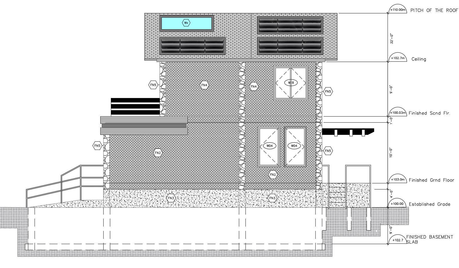
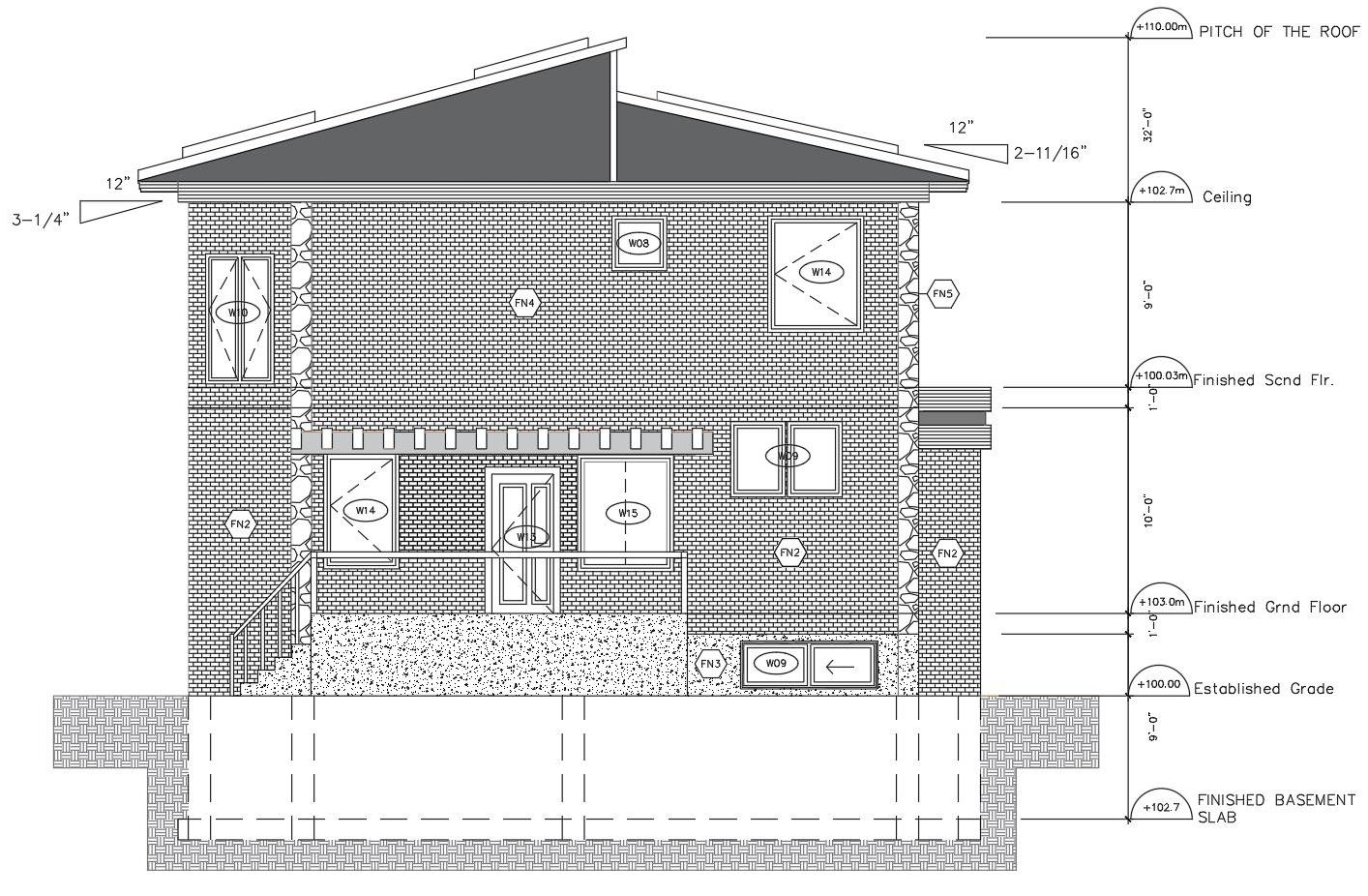
 WEST ELEVATION
WEST ELEVATION
WEST ELEVATION
SOUTH ELEVATION EAST ELEVATION
ELEVATIONS
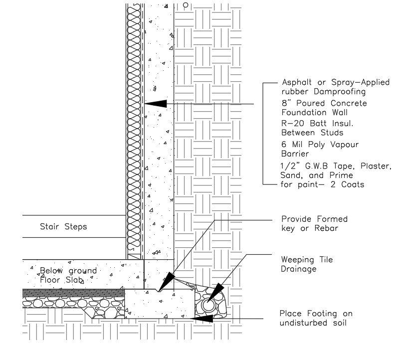
 Foundation wall
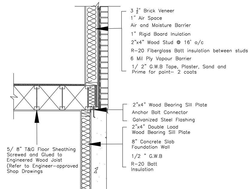
Floor/Exterior Wall connection
Foundation wall
Floor/Exterior Wall connection
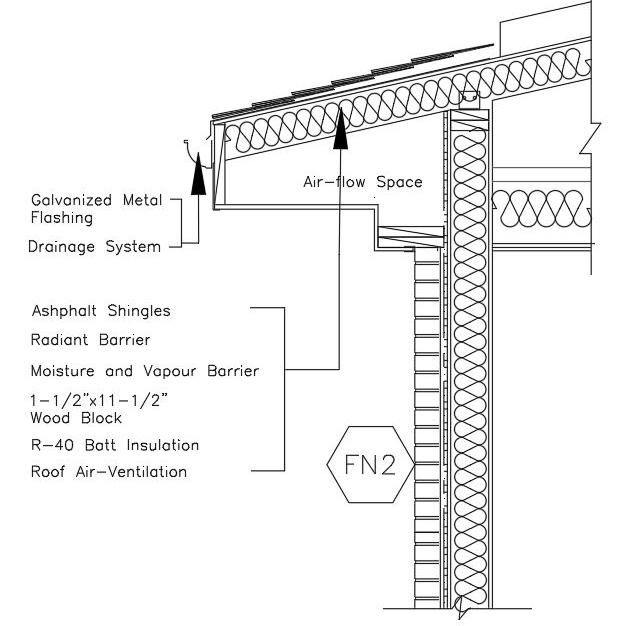
BASEMENT LEVEL FLOOR PLAN Roof/ Exterior Wall
Construction Details Plans
DETAILS
FN1 - Poured Conc. Foundation wall
POURED CONC. FOUNDATION WALL, MIN. 4’-0” BELOW FINISHED GRADE. BACKFILLED ON BOTH SIDES ON POURED CONCRETE FOOTING ON UN DISTURBED SOIL.
FN2 - Typical Below-grade Foundation

DRAINAGE MEMBERANE, ASPHALTIC OR SPRAY-APPLIED DAMPROOFING. 8” POURED CONC. FOUNDATION WALL, 2x3-1/2” WOOD STUDS @ 16” o/c. R20 BATT INSULATION BE TWEEN STUDS. 6 MIL POLY VAPOUR BARRIER
1/2” G.W.B. TAPE, PLASTER, SAND, AND PRIME FOR PAINT. 2 COATINGS
F1- Typical Slab-On-Grade Construc-

POURED CONC. FOUNDATION WALL 4’-0” BELOW GRADE, BACKFILLED ON BOTH SIDES. POURED CONC. FOOTING ON UNDISTURBED SOIL
F2- Typical Floor Consturction
FLOOR FINISH ON 5/8” T&G FLOOR SHEATHING, SCREWED AND GLUED TO ENGINEERED WOOD JOISTS.
F3- Typical Floor Cons. Stair Landing
FLOOR FINISH ON 5/8” T&G FLOOR SHEATHING SCREWED AND GLUED TO WOOD JOIST. 1/2” GYPSUM CEILING BOARD, TAPE, PLASTER, SAND AND PRIME FOR PAINT (2 COATINGS)
W1 - Typ. Above-grade Foundation
3-1/2” BRICK STONE VENEER, 1” AIR SPACE, AIR BARRIER/ MOISTURE BARRIER, 1” RIGID BOARD INSU. 1/2” EXTERIOR GRADE OSB.
2X8 WOOD, R20 BATT INSUL. 6 MIL POLY VAPOUR BARRIER, 1/2” G.W.B.
W2 - Interior Partition Wall
1/2”
GYPSUM WALL SHEATHING BOTH SIDES (USE W/R DRYWALL IN WASHROOMS) TAPE, PLASTER, SAND AND PRIME FOR PAINT -2 COATS. 2”x5-1/2” WOOD STUDS @ 16” O/C R20 BATT INSULATION. (6-1/2” THICK WALL)
W3 - Interior Partition Wall
1/2” GYPSUM WALL SHEATHING BOTH SIDES (USE W/R DRYWALL IN WASHROOMS) TAPE, PLASTER, SAND AND PRIME FOR PAINT -2 COATS. 2”x5-1/2” WOOD STUDS @ 16” O/C
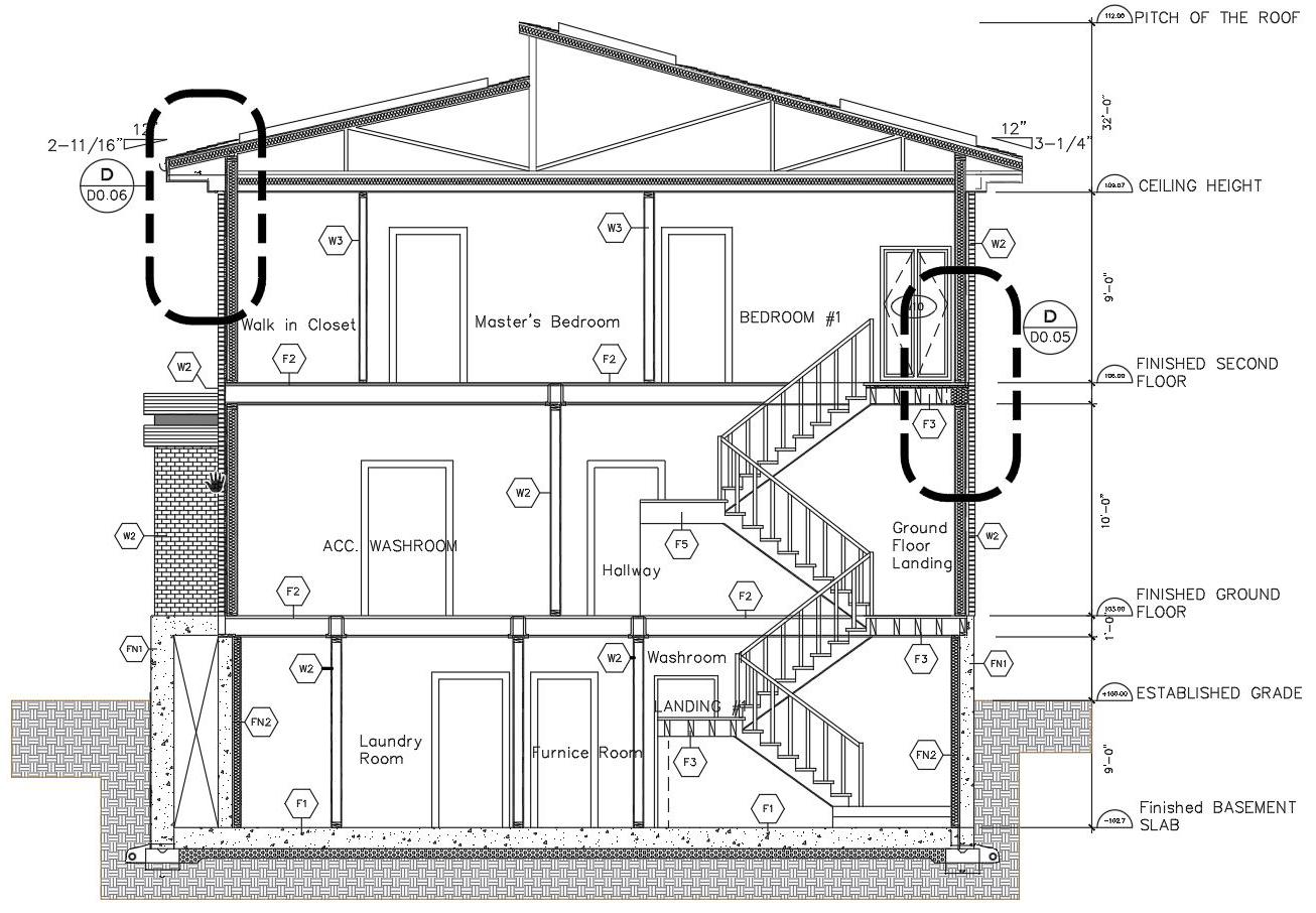
CROSS-SECTION ELEVATION
ASSEMBLY
A proposed Industrial project that is mainly focused on a Warehouse and an Office main type of Occupancy.

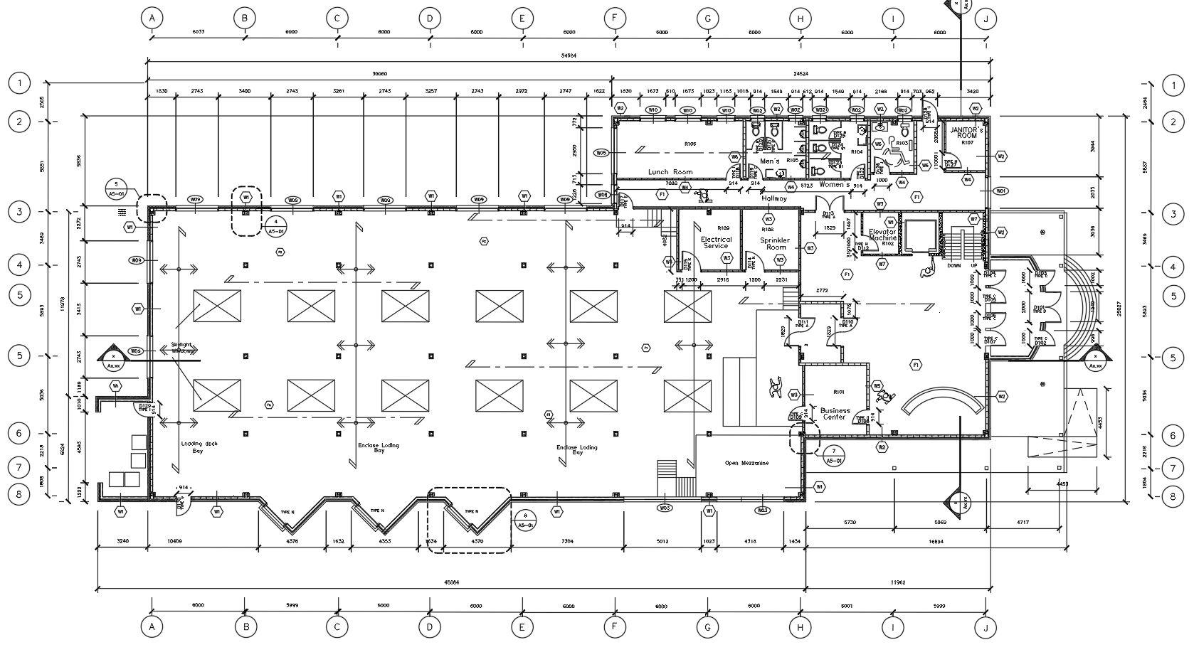

Orienting the warehouse at the ground floor gives the building an efficient and effic tive area for a workplace. By also adding an Office on the ground and second floor level gives the workspace to be more productive for the workers who will occupy the space. This project also provides good air ventilation and light accessibility.
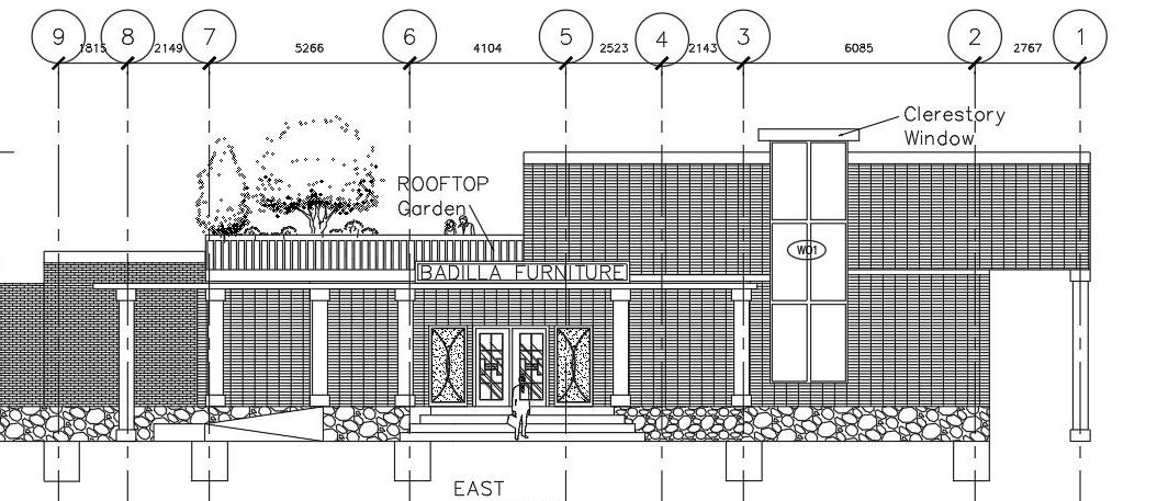
This design also highlitghts a green roof top garden where all the workers can relax while taking a break from work. As part of a sustainable strategy
GROUND LEVEL
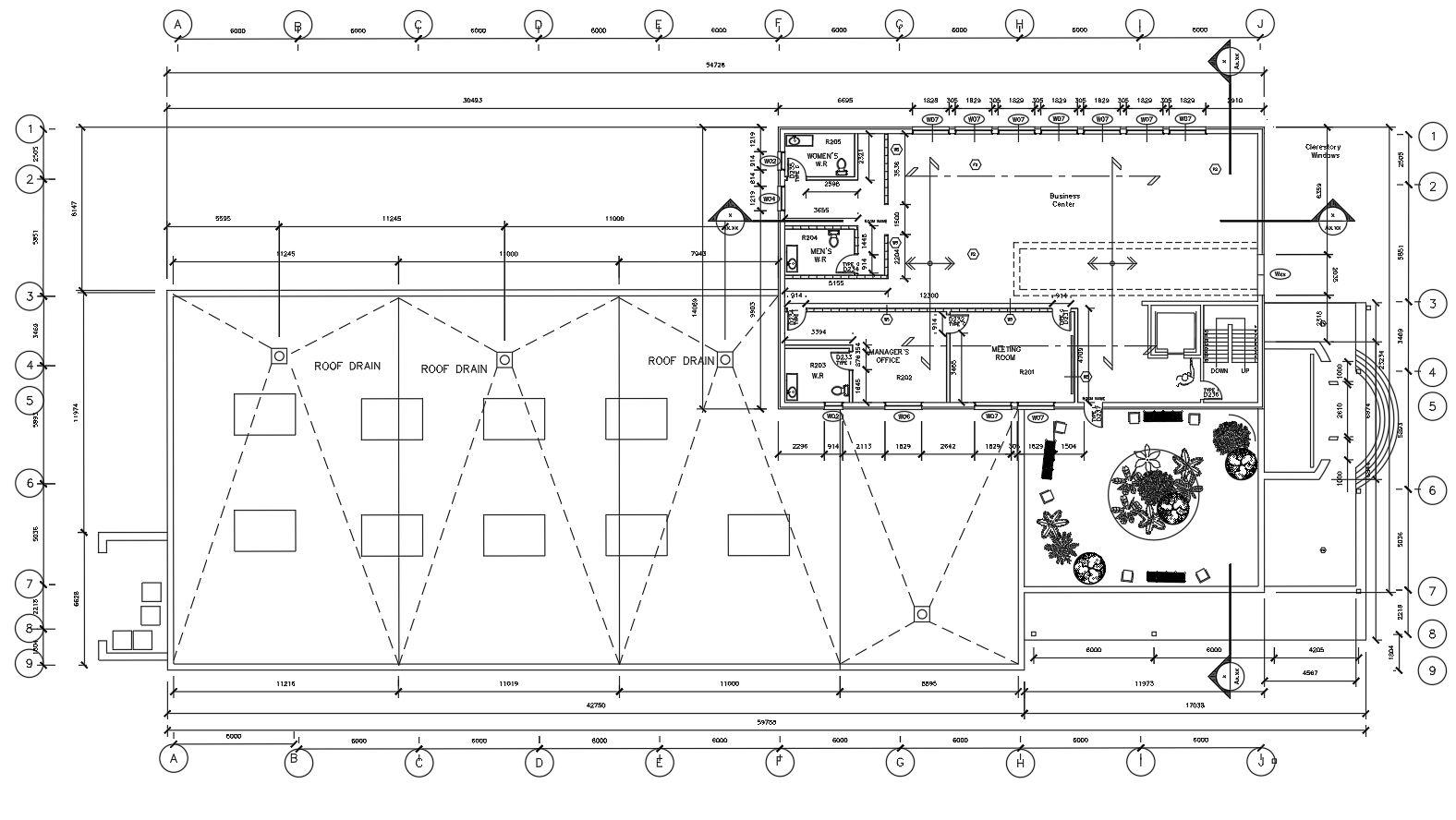
SECOND FLOOR SoftWare Used AutoCad PROJECT: 2 INDUSTRIALBUILDING
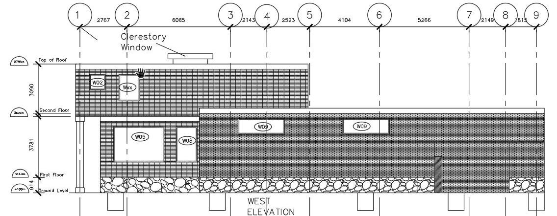
ELEVATIONS
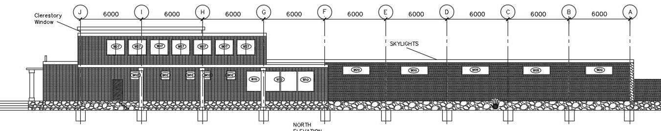
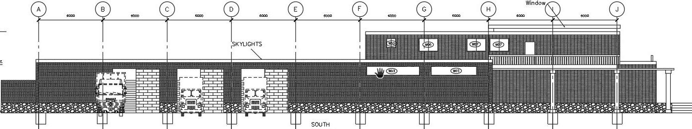
NORTH ELEVATION
WEST ELEVATION
EAST ELEVATION
SOUTH ELEVATION
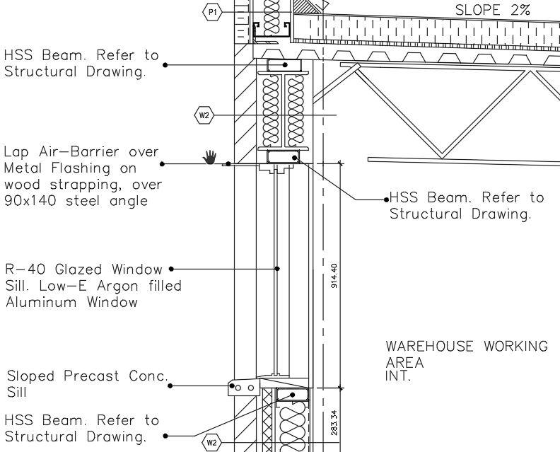
TYPICAL WINDOW TO WALL CONNECTION
Garbage collection area
General Area (Warehouse)
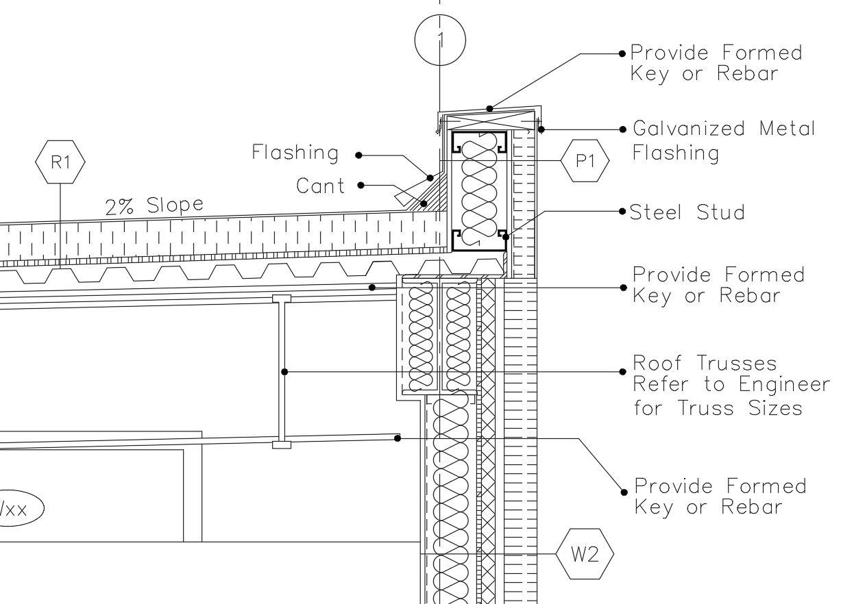
TYPICAL PARAPHET ASSEMBLY DETAIL
FOUNDATION WALL PLAN DETAIL

PARAPHET PLAN DETAIL
Ventillation/Clere story window Second-Floor Office Area
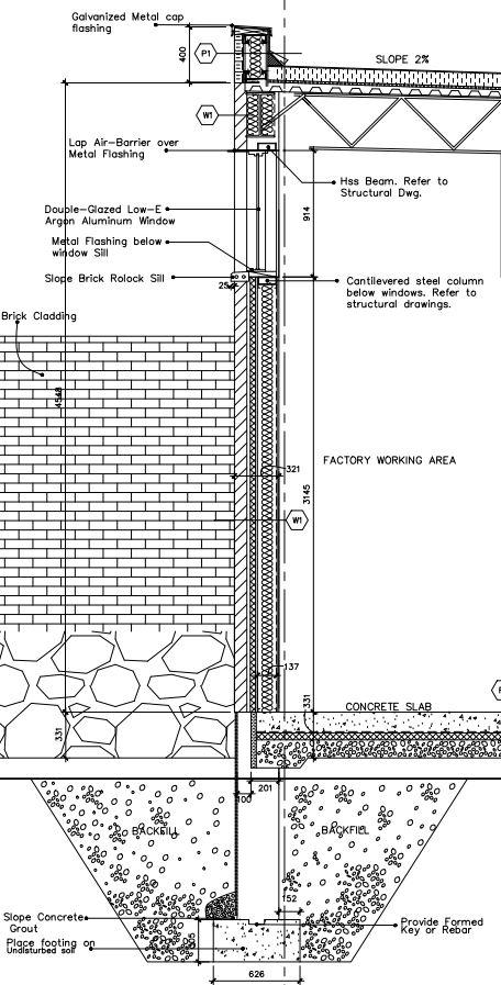
WALL DETAIL
Ground-floor Warehouse Office Second-floor Clerestory Window Building Main Entrance
CROSS-SECTION
TYPICAL WALL SECTION DETAIL
A proposed commercial project that serves as a Mercantile and Office building type of occupancy. The unit is composed of 4 Retail space area where people can shop and relax while also having a dining area (restaurant)
By having two (2) buildings separat ed we can segregate people who wants to shop in a retail store or eat at a Restaurant. This design will also cater the people who works in the office area and provide their needs.

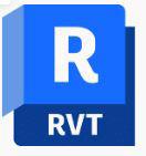
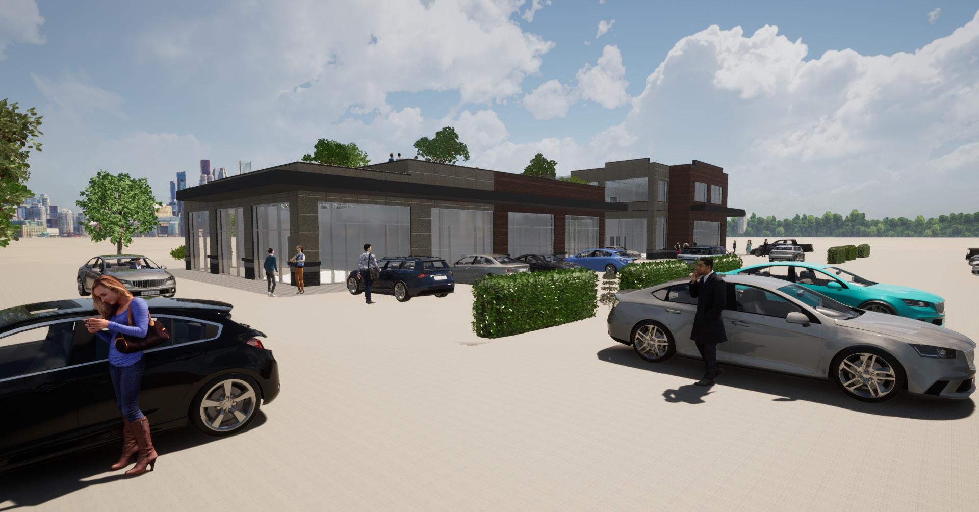

SoftWare Used Revit Twinmotion PROJECT: Commercial Plaza
GROUND FLOOR LEVEL
SECOND FLOOR LEVEL
FIRST FLOOR
Retail Spaces (4) 90 sqm each
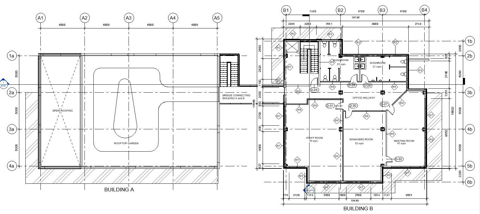
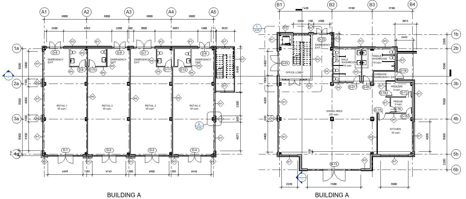
Dining Area (restaurant) with fully func tioning kitchen area. (220 sqm)
SECOND FLOOR
Rooftop garden accessible for office work ers.
Office unit occupancy with fully function ing
Staff room Manager’s room Meeting room
NORTH ELEVATION
EAST ELEVATION
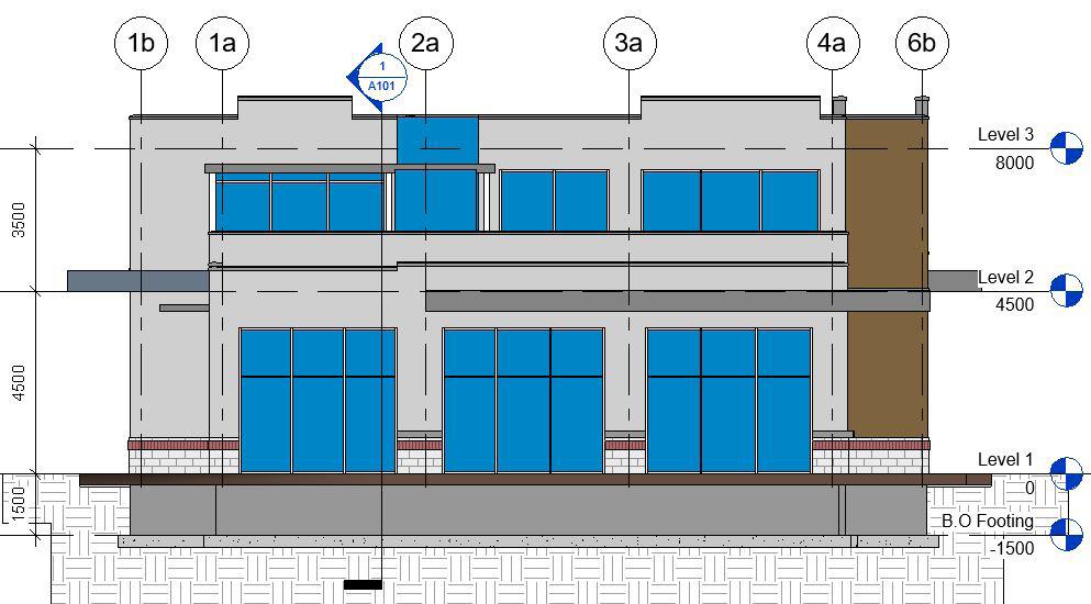
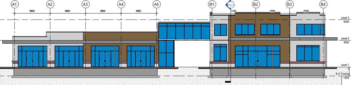
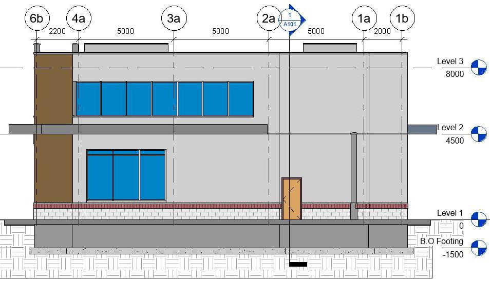
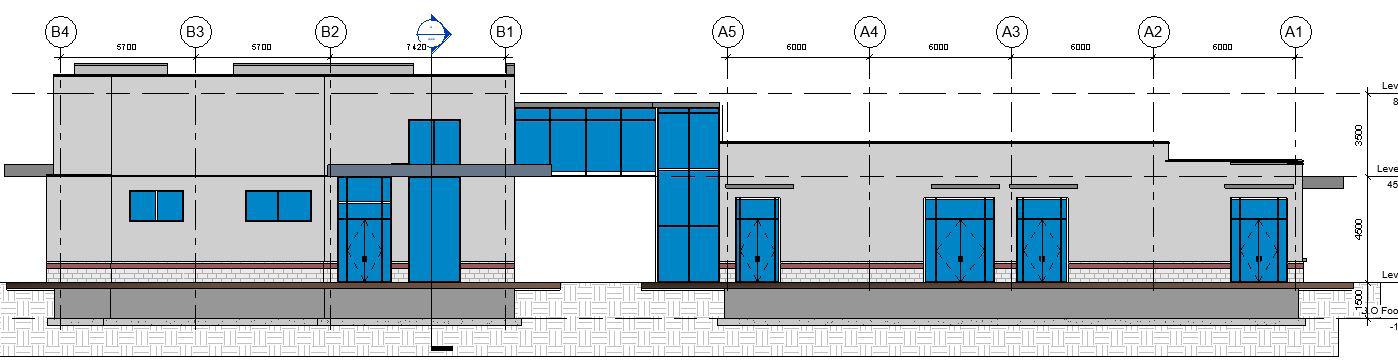
SOUTH
WEST
ELEVATION
ELEVATION
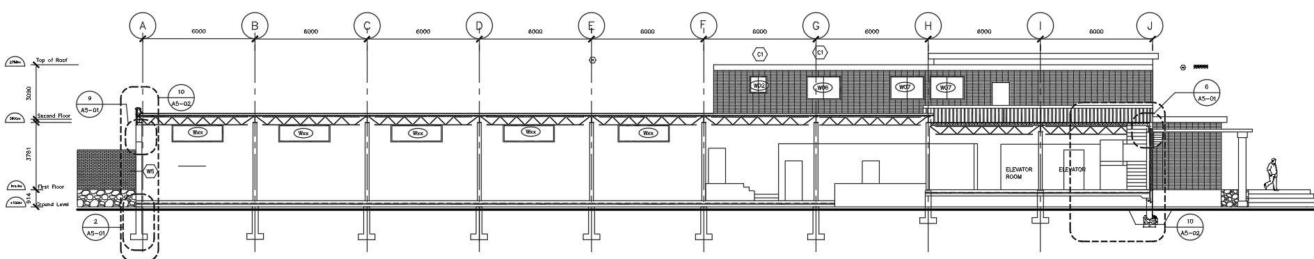
CROSS SECTION ELEVATION
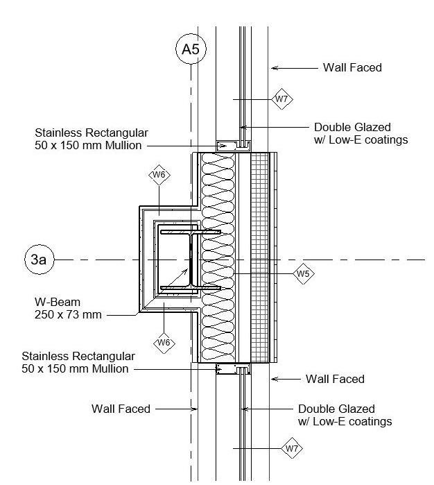

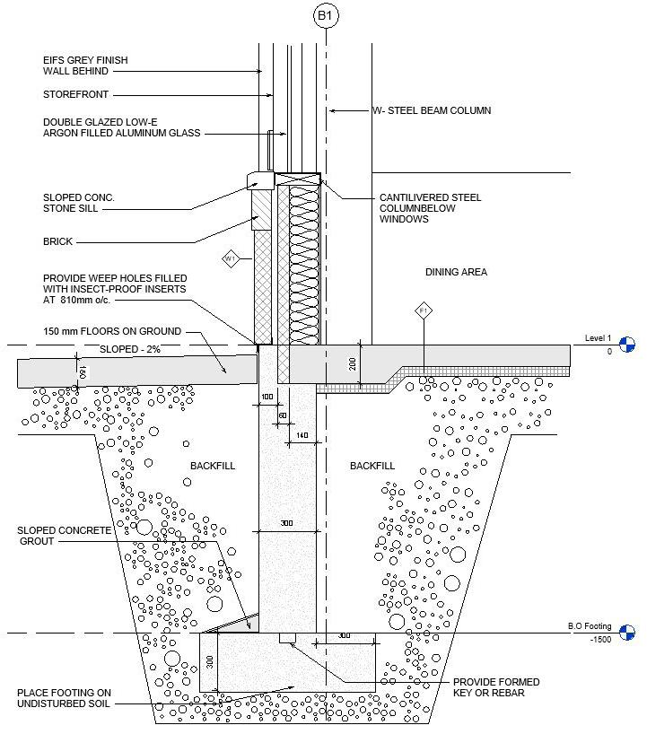


Level Level 1 0 Level 4500 Level 2 4500 Level 8000 Level 3 8000 A1 A2 A3 A4 A5 B1 B2 B3 B4 6000 6000 6000 6000 7420 5700 5700 B.O Footing 1500 B.O Footing 1500 A103 A102 RETAIL 1 RETAIL 2 RETAIL 3 RETAIL 4 BRIDGE OFFICE HALLWAY OFFICE LOBBY RESTAURANT KITCHEN W2 W7 W1 W6 W6 W6 W2 W1 W2 ELEVATOR SHAFT 3819 1500 4500 3500 1 50 Section 3 1 Level 2 4500 A1 W2 404 W7 SLOPE 2% W BEAM 250 x 73 mm SUSPENDED CEILING GALVALUME MTL CAP FLASHING AND FASCIA PROVIDE DRIPS AS SHOWN BELOW Cant Flashing Fully adhered roof membrane Wall Faced (EIFS) O.W.S.J Double Glazed window w/ Low E Coatings 50 mm x 150 mm Rectangular Mullion STEEL STUD A2 GALVALUME MTL CAP FLASHING AND FASCIA PROVIDE DRIPS AS SHOWN PARAPHET www.autodesk.com/revit Consultant Address Address Phone Fax e mail Consultant Address Address Phone Fax e mail Consultant Address Address Phone Fax e mail Consultant Address Address Phone Fax e mail Consultant Address Address Phone Fax e mail No.DescriptionDate typ. parapet construction detail A1 Faced (EIFS) Level 2 4500 A2 W2 P1 R1 R2400 1099 COLUMN GALVALUME MTL CAP FLASHING AND FASCIA PROVIDE DRIPS AS SHOWN PARAPHET PARAPHET SLOPE 2% O.W.S.J W 310x38 BEAM Fully adhered membrane Flashing Cant Green Roof Seed mix Drainage Layer Paver With Shim Cant Concrete Pavement STEEL STUD CONSTRUCTION AND ASSEMBLY DETAILS typical foundation wall assembly typ. parapet connecting two (2)typ. wall and window wall assembly RETAIL UNITS ROOFTOP GARDEN SKYE BRIDGE RESTAURANT OFFICE AREA
A proposed Senior’s Housing that is considered to be a complex project. This proposal cater’s Seniors who need constant care and seniors who are retired.
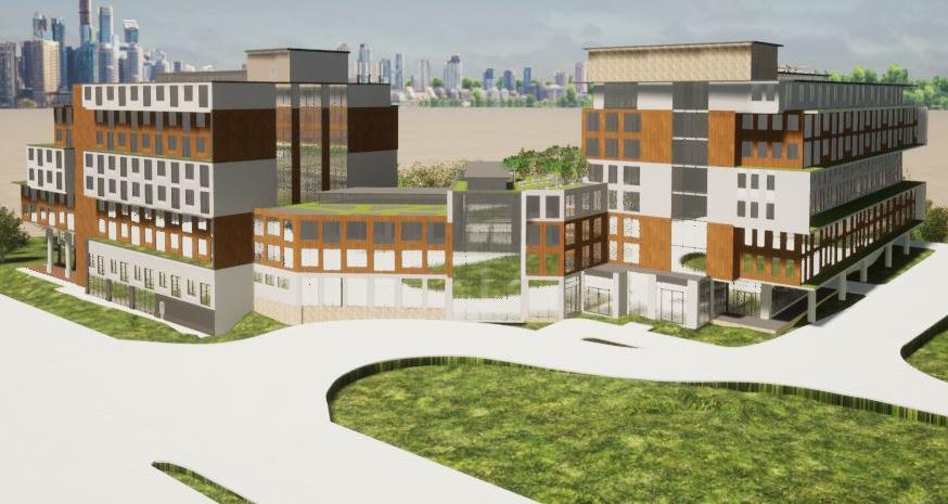
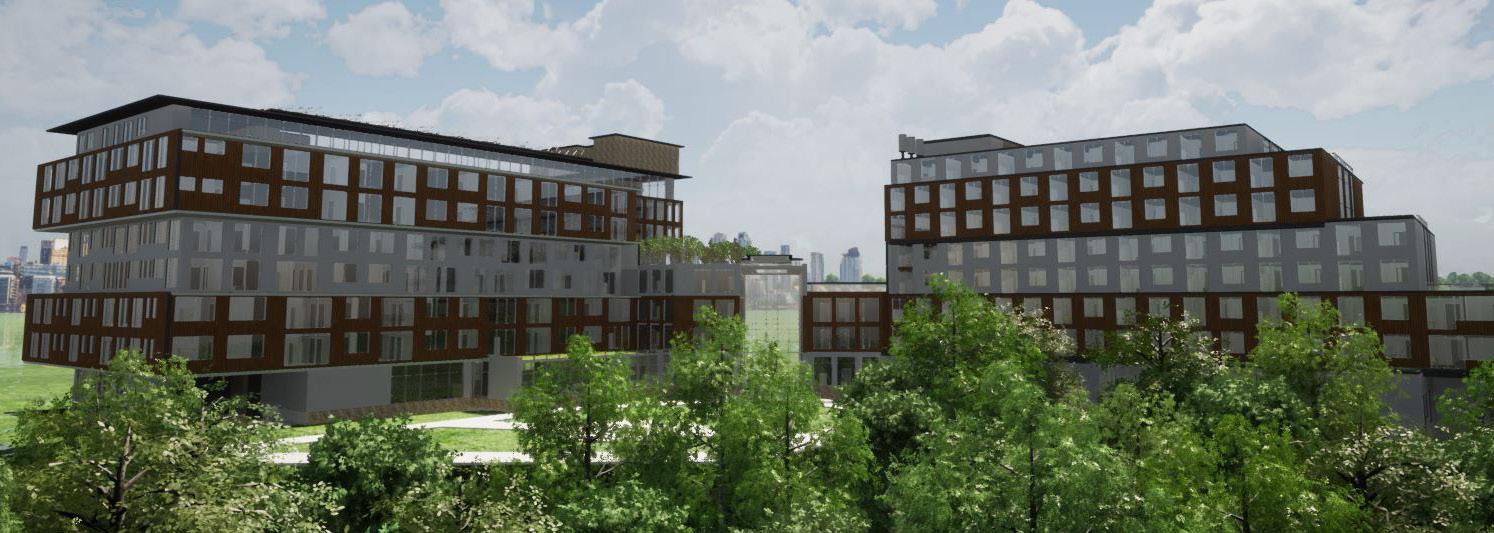
This design implements a three-way sys tem buildings that separate a portion of each category of Seniors (Couples, Singles, and a Senior who needs constant attention by the care giver.
By having a Center building that sepa rates Building A to Building B we can maxi mize the space of the area while adding vol ume to the site at the same time.

COMPLEX PROJECT: SENIORS HOUSING SoftWare Used Revit Twinmotion
BUILDING A
OFFICE UNITS
DAY-CARE CENTER LIBRARY
DINING HALL
CENTER BUILDING
ARTRIUM

RECEPTION AREA
GREEN WALL AREA
BUILDING B
BACHELOR UNITS
1- BEDROOM UNIT
POOL AREA
GAME ROOM
UPUP DN UP UP UP UP UP UP 2f 3f 4f 5f 7000 7000 7000 Bf Cf Df Ef Ff Gf Hf If Jf Kf Lf Mf Garbage Collection 19 m² Care Room 15 m² Care Room 15 m² Care Room 34 m² Entrance Air Lock 15 m² Office 11 m² Office 10 11 m² Office 11 m² W.R 12 3 m² W.R 13 86 m² Library 14 68 m² Loading Dock 15 58 m² Kitchen 16 18 m² Storage 17 Ac Bc Cc Dc Ec Fc 6000 6000 6000 6000 30000 6000 399 m² Dining Hall 5 37 m² Bachelor 7 39 m² Bachelor 39 m² Bachelor 23 38 m² Bachelor 24 Reception Area Center Building Atrium Green Wall Reception Area For Care Room 21 m² Room 177 47 m² Entrance Air Lock 178 Redundant Room Vestibule 179 0 5m 10m 20m 50m 462 m² Open Space 180 A3.01 A3.01 W1 W4 W4 W1 W4 W5 W5 W5 W5 W5 W5 W4 W4 W1 W1 W1 W4 W4 W4 1 A1.14 1 A1.16 BACHELOR BACHELOR BACHELOR BACHELOR BACHELOR BACHELOR BACHELOR BACHELOR BACHELOR BACHELOR BACHELOR BACHELOR ONE BEDROOM ONE BEDROOM W4 W5 W5 W5 W5 W5 W5 W5 W5 W5 W5 W5 W5 W5 W5 W1 W4 W4 W4 W5 W5 W5 W5 W5 W5 W5 W5 W4 W1 W5 W7 W7 W7 W7 W5 W5 W5 W5 W5 W5 W5 W5 W5 W5 W1 W4 W1 W4 W1 W1 W1 W5 W5 W5 W5 W5 W5 W1 W2 W9 1s 2s 3s 4s 5s 6s 7s 8s 9s CsBsAs FsEsDs 10s Gs Hs 1f 7000 28000 Af 6000 6000 6000 6000 6000 6000 6000 6000 6000 6000 8644 6000 74644 1 : 200 Ground Level 1
HALLWAY
OPEN TO BELOW ATRIUM SPACE HALLWAY
GREEN

2f 3f 4f 5f Bf Cf Df Ef Ff Gf Hf If Jf Kf 1 A3.01 1 A1.12 6000 6000 6000 6000 6000 6000 6000 6000 6000 7000 7000 7000 1f Af 6000 7000 28000 60000 D06 D02 D01 D12 D12 D08 W4 W4 W2 W4 W2 W2 W4W2W4W2W2W2 W2W2W2W2W2W2W2W2W2W2
ROOF W2W2W2W2W2W2W2W2W2W2W2 D01 D01 D01 D08 D12 D12 D08 D12 D12 D08 D01 D01 D08 D12 D12 D08 D12 D12 D12 D12 D08 D08 D12 D12 D12 D12 D08 D08 D12 D12 D01 D01D01D01D01 D12 D12 D12 D12 D01 D01 D12 D12 D08D08 D12 D12 D12 D12 D01D01 D08 D11 D08 D01 W5 W5 W5 W5 W5 W5 W5 W6 W5 W6 W5 W6 W5 D04 D04 D04 D04 W6 W5 W6 W6 W6 W6 W5 W6 W6 W6W5 W5 W6 W6 W6 W6 W5 W6 W6 W6 W6 D04D04 D04 D04 D04 D04 D04 D04 D04 D04 D08 D04 D04 D04 D04 D04 D04 D04 D04 D04 D04 D04 W2 W2 W2 W2 W2 W2 W2
D08 W6 W6 D08 D04 D08 D12 900 900 2100 2100 2500 1400 1400 2300 1200 1300 2300 2229 D01 W6 W5 D04 D04 W6 W6 W5 W5 W5 W5 W5 W5 W5 W5 W5 W5 W5 W5 D02 D01 D08 D01 D04 D04 W6 W5 2 BEDROOM SUITE B.R 2 B.R 1 2 BEDROOM SUITE 2 BEDROOM SUITE 2 BEDROOM SUITE 2 BEDROOM SUITE W6 D12 2 BEDROOM SUITE 2 BEDROOM SUITE 1 BEDROOM SUITE 1 BEDROOM SUITE D02 2 BEDROOM SUITE 2 BEDROOM SUITE 2 BEDROOM SUITE 2 BEDROOM SUITE 2 BEDROOM SUITE 2 BEDROOM SUITE 2 BEDROOM SUITE BACHELOR BACHELOR B.R 2 B.R 1 B.R 2 B.R 1 B.R 2 B.R 1 B.R 2 B.R 1 B.R 2 B.R 2 B.R 2 B.R 1 B.R 1 B.R 1 B.R 2 B.R 1 B.R 2 B.R 1 B.R 2 B.R 1 B.R 2 B.R 1 B.R 2 B.R 1 B.R 2 B.R 1 B.R 2 B.R 1 2847 2800 3800 2300 3300 2300 2200 3300 3300 2300 2600 3300 W2W4W4 W4 W4 W4 W4 W4 W4 W4 W4WN12WN9WN9WN10WN12WN9WN11WN10 2300 2600 2800 2800 2300 2800 2300 2300 1700 1100 1150 1680 2300 2300 1600 1300 1300 2420 1200 1235 W4 D02 D02 Checked Drawn Date Project Francis ARCHITECTURE Unit No.DescriptionDate TYPICAL FLOOR PLAN BLOW- OUT DETAIL 2- BEDROOM Units
NORTH ELEVATION
EAST ELEVATION
SOUTH ELEVATION
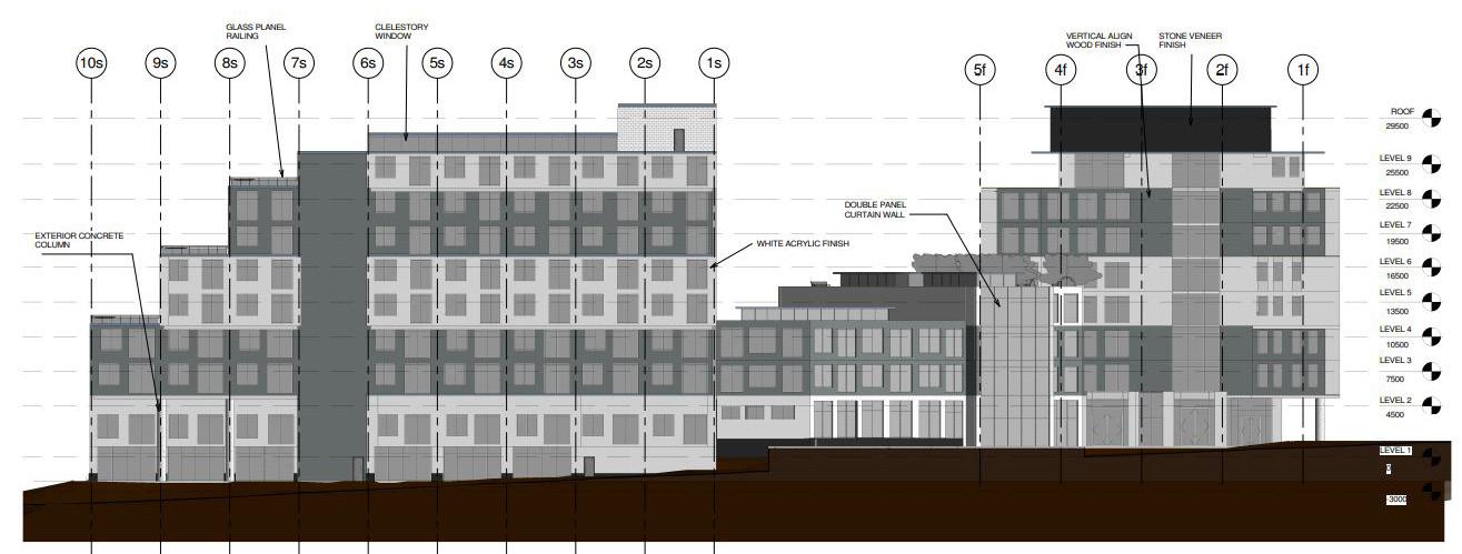
WEST ELEVATION
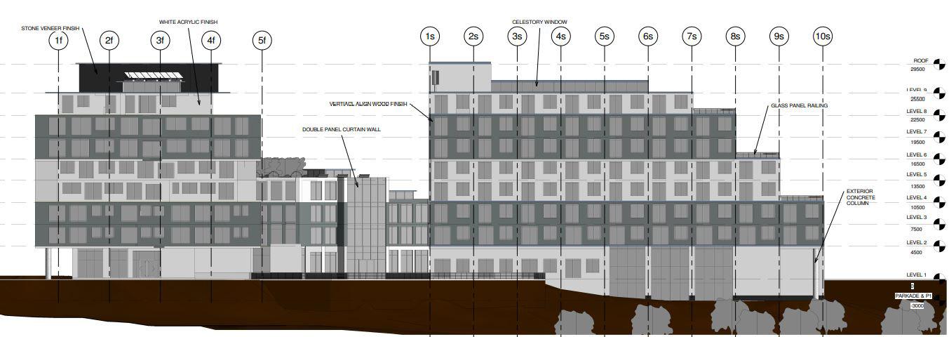
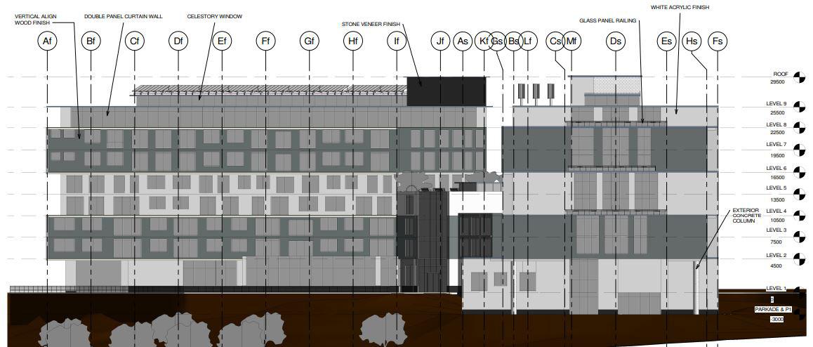
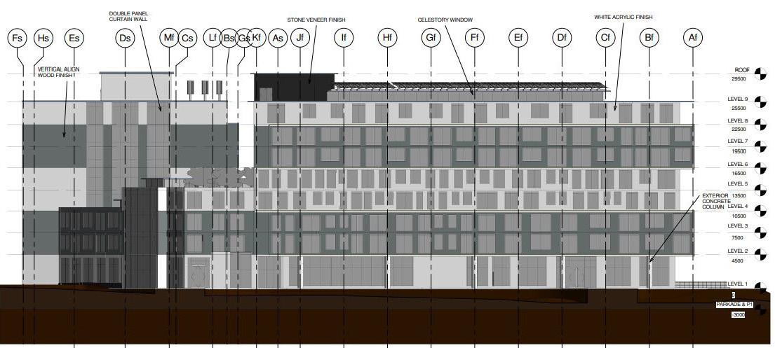
ELEVATIONS


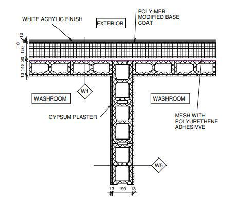
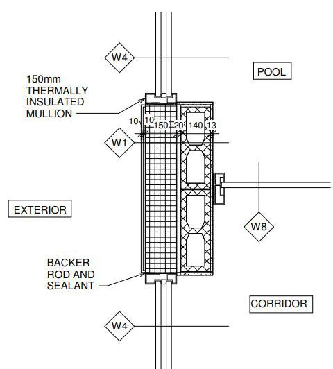

Typ. Exterior Wall/ Window Wall con nection Typ. Exterior Wall/ Interior wall connection Typ. Wall to Door Assembly con nection Ground Level 0 Level 2 4500 Level 3 7500 Level 4 10500 Level 5 13500 Level 6 16500 Level 7 19500 Level 8 22500 Bf Cf Df Ef Ff Gf Hf If Jf Kf Lf Mf Level 9 25500 3000 3000 3000 3000 3000 3000 3000 4500 3 A4.01 Level 1 Underground 3000 Roof Skylight Roof 27000 Basement 4 6000 Basement 5 29500 Af 1500 2500 W1 W2 W2 W1 W2 W2 W5 W1 W2 W2 W1 W1 W2 W2 W4 FN1 W4 R3 F2 F2 F2 F2 F2 F2 F2 F1 F2 R1 SOLAR PANELS R3 F2 F2 F2 F2 F2 F2 F2 F2 UNDERGROUND PARKING GROUND LEVEL COMMON AREA ATRIUM CLERESTORY WINDOW Suite Level 2 Suite Level 3 Suite Level 4 Suite Level 5 Suite Level 6 Suite Level 7 Suite Level 8 Construction North 1 : 130 Left Wing Building Section1
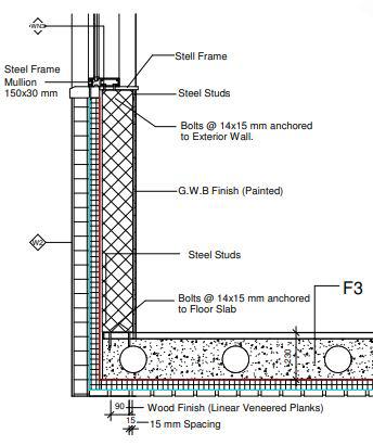
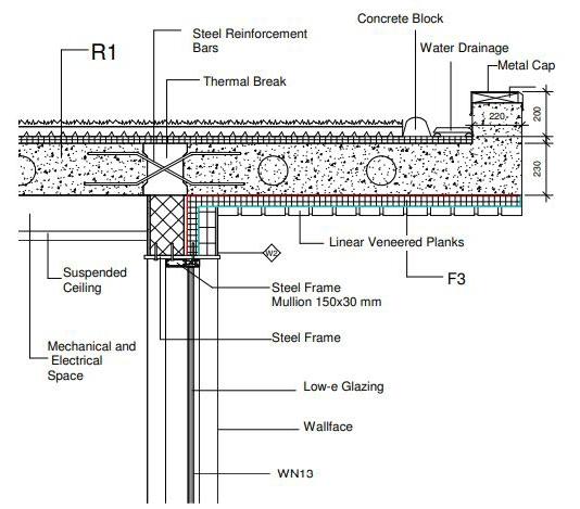


TYP. CROSS SECTION ELEVATION TYP. FOUNDATION WALL ASSEMBLY DETAILS TYP. CANTILEVERED SLAB/ EXT. WALL CONNECTION TYP. INTENSIVE ROOFING PARAPET ASSEMBLY Cross-sectional Elevation 300 300 DAMPPROOFING BOND BREAK 250 mm CONCRETE SLAB CONCRETE FOUNDATION WALL DRAINAGE PIPE GEO FABRIC WRAP GRAVEL SURROUNDING THE PIPE RIGID INSULATION CONCRETE FOOTING 6 mm POLY VAPOR BARRIER UNDER FLOOR GRAVEL RIGID INSULATION W2 R1 Mechanical and Electrical Space Suspended Ceiling Wallface WN13 Thermal Break Low Steel Frame Mullion 150x30 mm Steel Frame Steel Reinforcement Bars Francis & Wei ARCHITECTURE 2770 230 230 2770 1 BEDROOM SUITE 2 BEDROOM SUITE F2 F2 F2 R3 W4 R3 CANTILEVERED ROOF 2418 2926 SUSPENDED CEILING SUSPENDED CEILING Ground Level 0 Level 2 4500 Level 3 7500 Level 4 10500 Underground Parking/ Basement Level 2500 3 A5.01 Level 10 3000 3000 3000 4500 2500 1 A5.01 2270 230 CARE FACILITIES 2 BEDROOM SUITE 2 BEDROOM SUITE W4 W1 W2 W4 W2 W4 W2 W4 2 BEDROOM SUITE 230 F2 F2 W4 F2 F1 2600 2600 F3 F1 4001 Suspended Ceiling Suspended Ceiling Suspended Ceiling Thermal Break 300 GRADE LEVEL Af R1 Conrete Block Water Drainage WN13 WN13
SOCIAL MEDIA ACCOUNTS


Insta: Archi.tistics
Linedin: Francis Badilla