
AssemblyInstructions
WelcomeToForesightSports
ThankyouforchoosingaForesightSportsEuropeSim-in-a-Box package,andwelcometotherapidlyexpandingglobalfamilyof ForesightSportsusers!
ClientsaroundtheworldrelyonForesightSportstechnologyfor themostaccurateandexcitingsimulatedgolfexperienceever developed,andatanytimeofthedayornighttherewillalways behundredsofpeopleutilisingthisincrediblecutting-edge technologyfortheirgolfingpleasureandgameimprovement.
Thisdocumenthasbeenputtogethertogiveyouthe informationyouneedtohelpyouinstallandthengetthebest outofyourSim-in-a-Box.
Pleasefamiliariseyourselfwiththedifferentsections-andthe contentthatfollows-tomaximiseyourenjoymentofthe system,andsoyouknowhowtoaccesstheadditionalservices andsupportthatyoumayrequire.
Wereallydovaluethefeedbackwereceivefromourcustomers. Ifyouhaveanysuggestionsorcommentsaboutus-orour service-wewouldlovetohearfromyou.
Onceagain,wethankyouforyourcustomandlookforwardto servingandsupportingyou.
Bestwishesfromusallandplaywell!
YourForesightSportsEuropeTeam

BeforeYouBegin
Measure and confirm you have enough space to safely install and play.
The final setup size of your simulator will be approximately 2.8m tall x 5.8m deep x 3.8m wide. Make sure you have extra space for the assembly process.
ImportantInformation
Please make sure you have an assistant during the assembly process. The frame assembly requires TWOPEOPLE to safely complete.
Make sure you have all the required and recommended tools before you start. It will make the build smoother and, more importantly, safer.
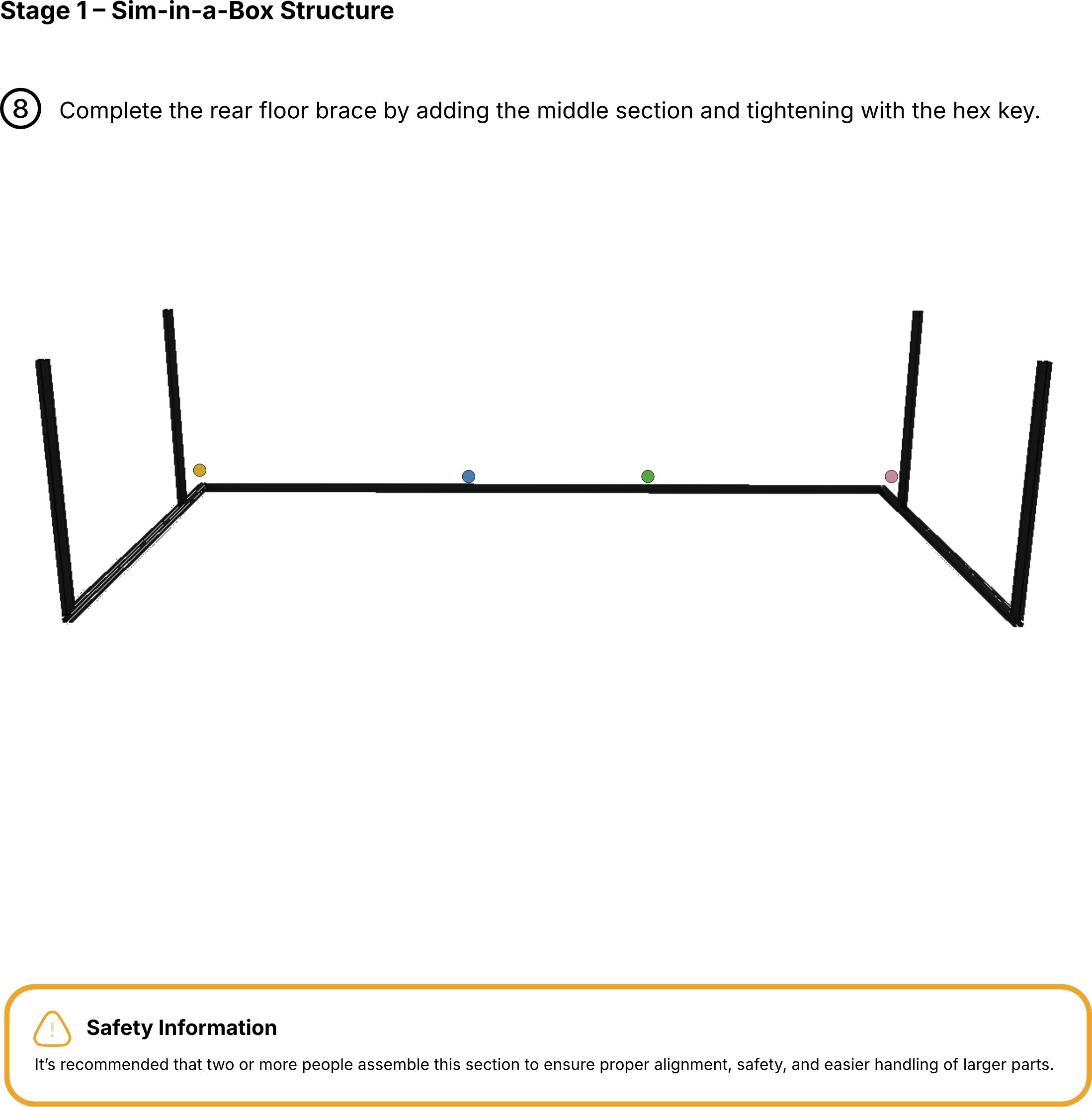
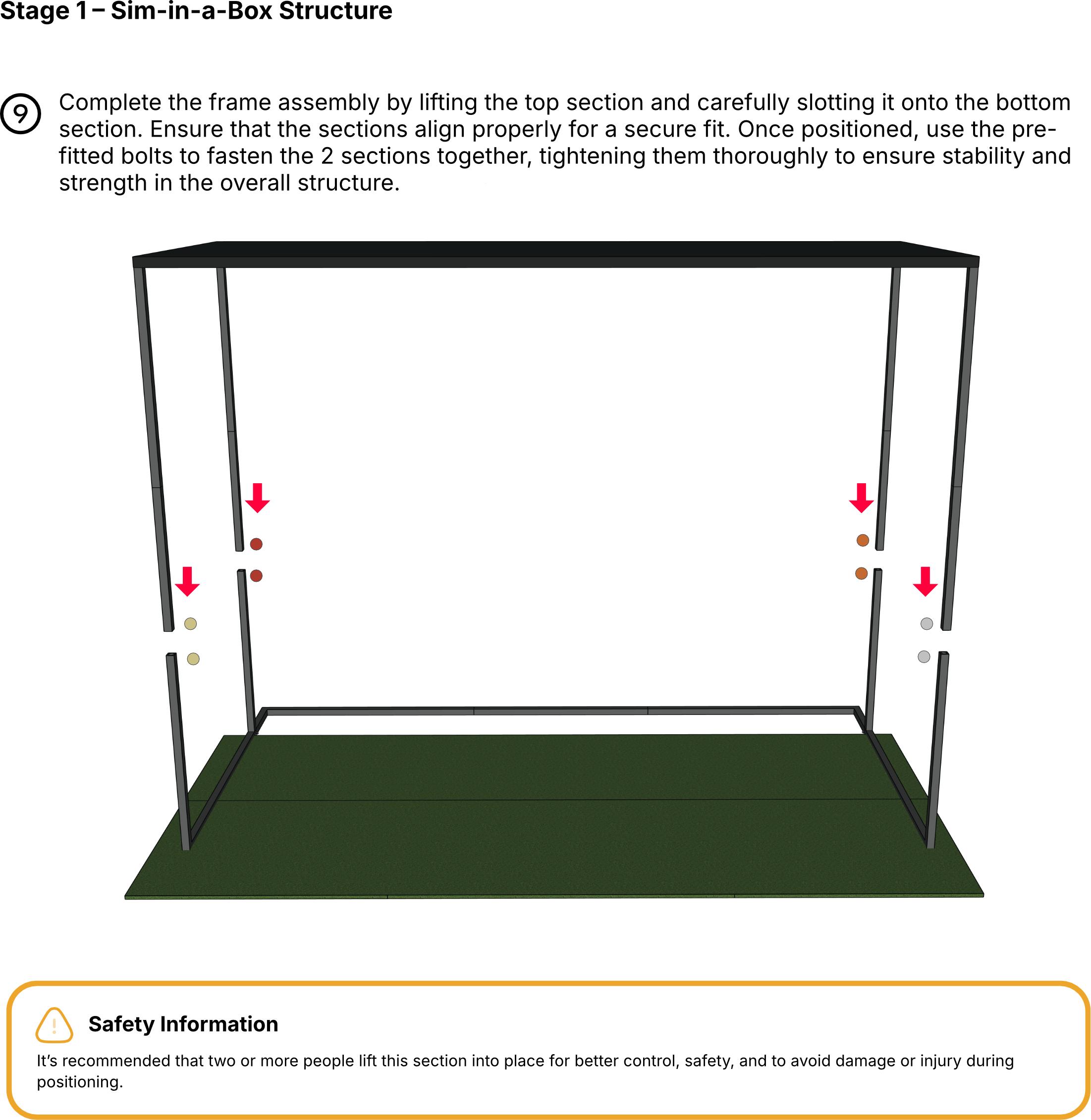
Work carefully so you donʼt injure yourself or damage the simulator. When connecting the frame sections, keep your fingers clear to avoid getting them trapped. Each connectable section is marked with coloured stickers. Match the corresponding colours to assemble everything correctly.
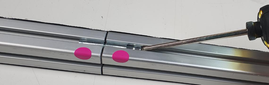
Please note: The hex key should be inserted at a slight angle when tightening or loosening the frame joining fixings.
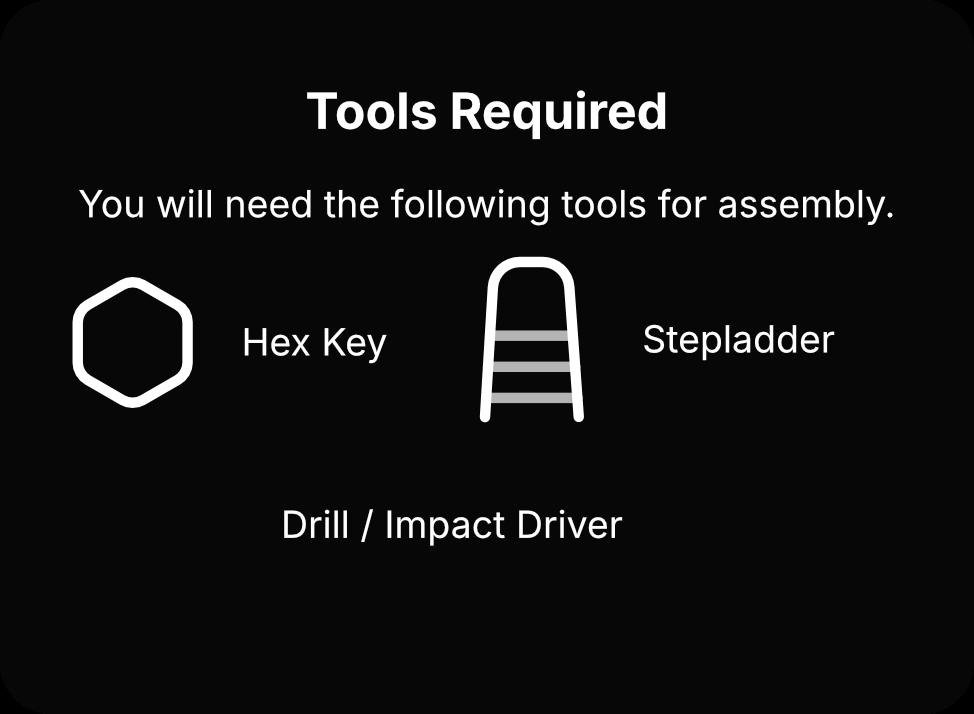
RecommendedTools
We recommend following tools for assembly.
Eye Protection Glasses
Work Gloves
Cutter (for cutting Zip ties)
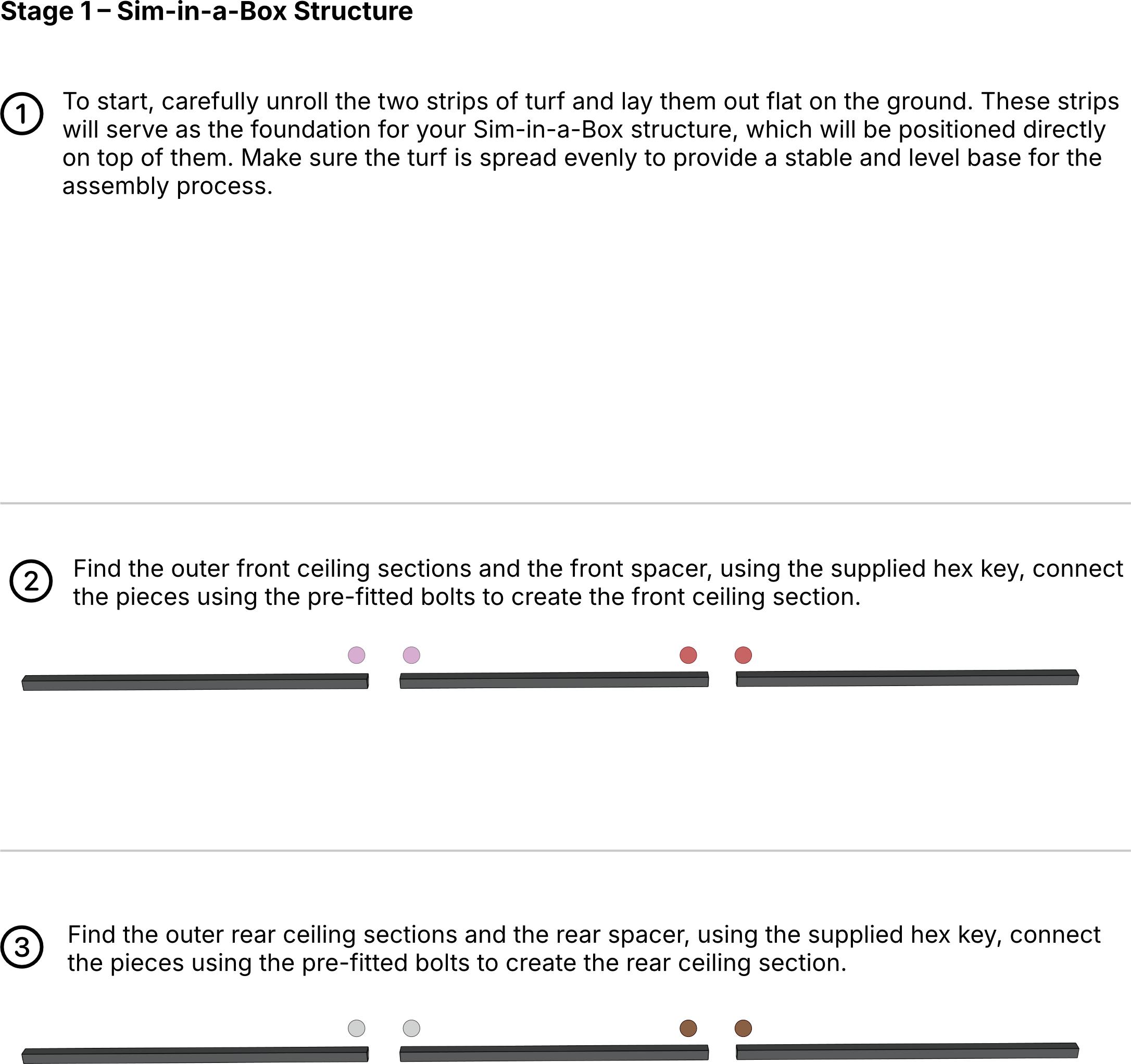
Stage1–
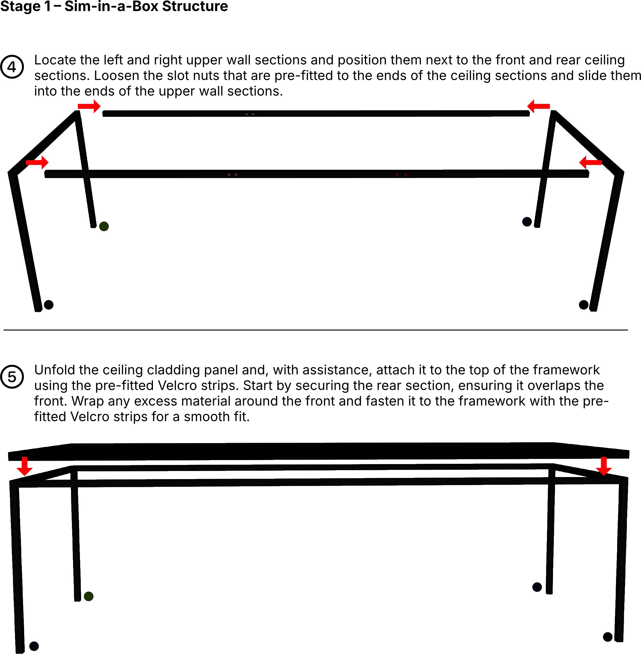
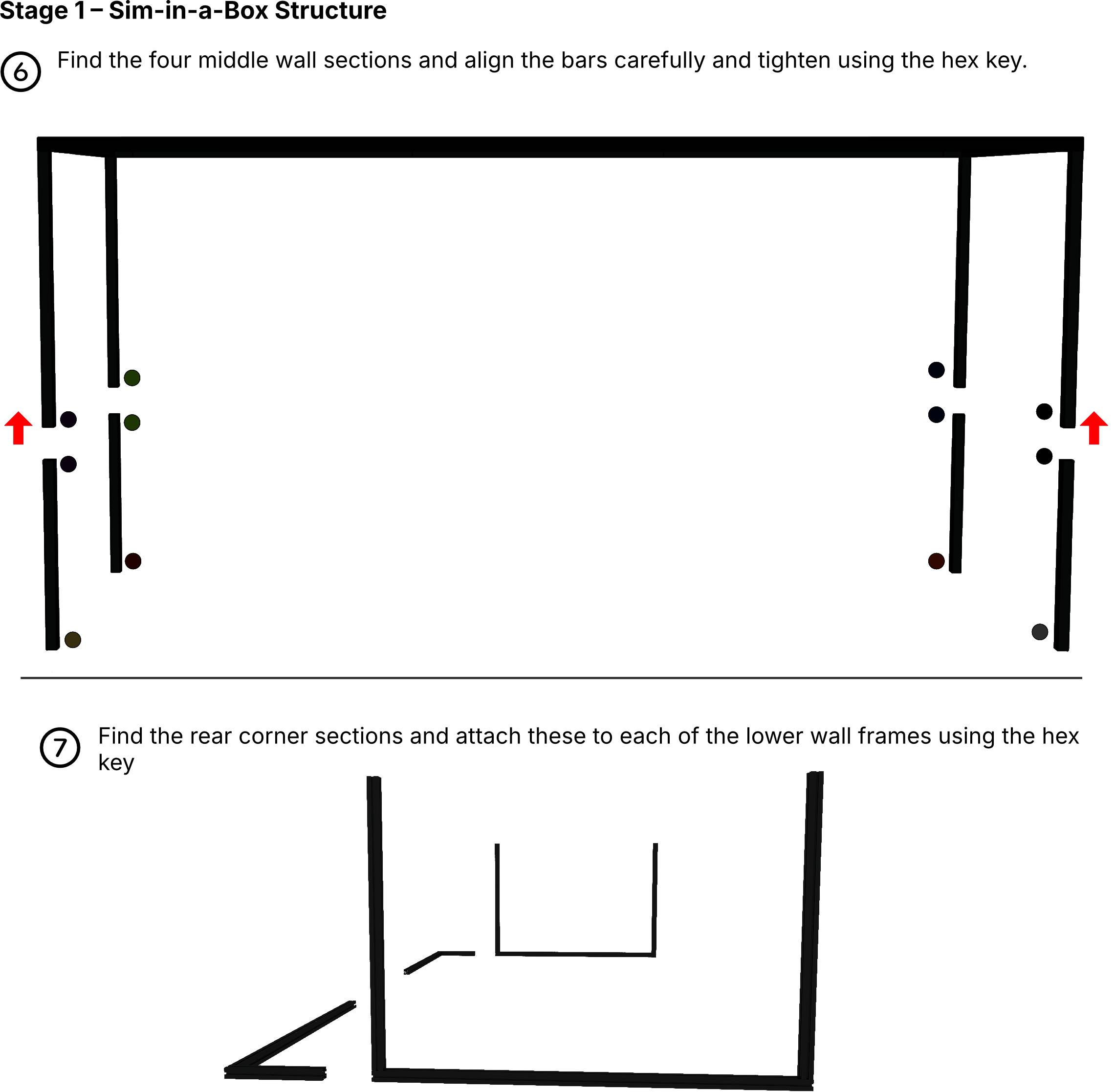
Find the 2 wall cladding panels and unfold them. Begin at the rear upright of the structure, attaching the panels in the same manner as the ceiling panel. The excess material at the front is intended to be wrapped around the upright and secured with the pre-fitted Velcro.
ScreenHangingInstructions
Please read and understand all of the instructions before commencing installation.
Before handling the screens, it is essential to ensure that your hands are clean. This will help prevent any dirt, grease, or moisture from transferring onto the screens, which could affect their appearance or functionality
Place the mesh impact screen on a clean surface, ensuring that the rod pockets are easily accessible.
Assemble the longest bungee-corded fibre rod set and then insert the resulting long rod into the top pocket of the mesh impact screen. Ensure that both ends of the rod fit securely into the internal fold of the pocket.
SafetyInformation
Do not run fingers along the surface of these rods as you may end up with small fibre splinters in your fingers, which are almost invisible but can be very irritating.
Assemble the remaining rod sets, then refer to instruction 3 above to insert the two shorter rods into the side rod pockets.
Stage2–ImpactScreen
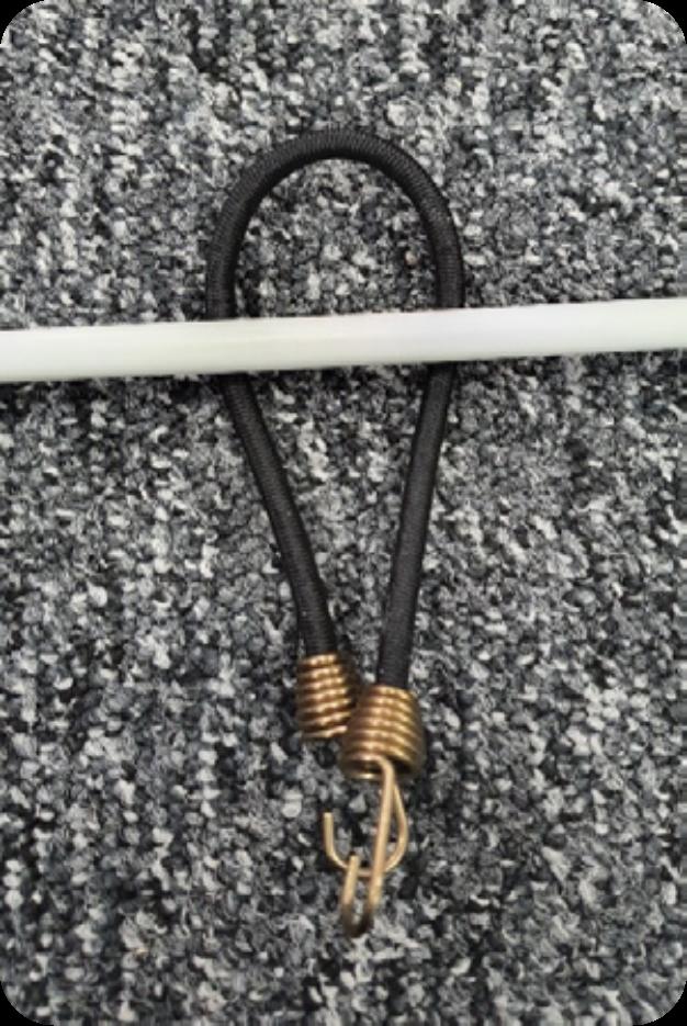
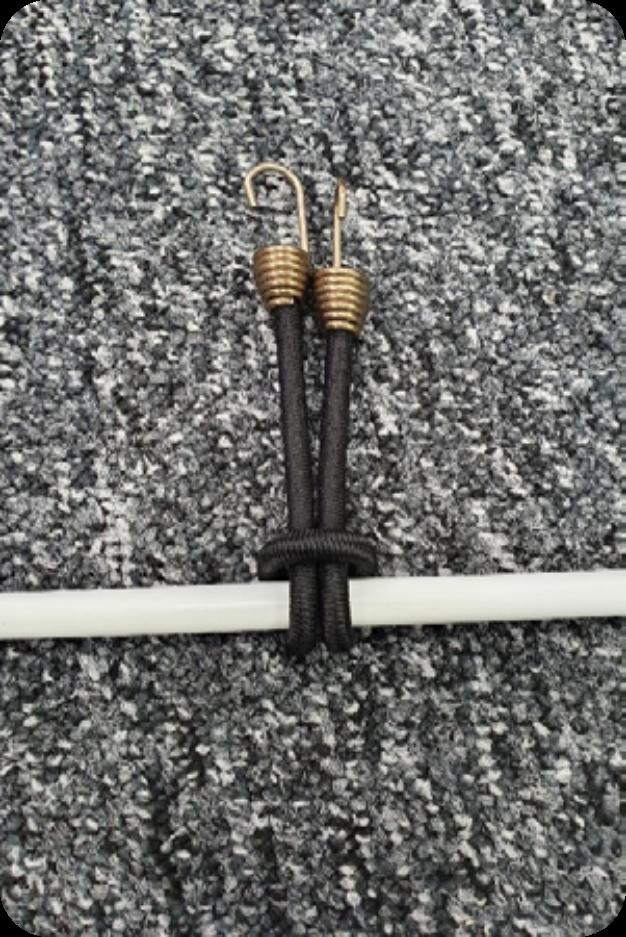
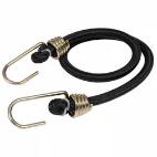
Fit a bungee into each cut-out by folding it in half. Pass the looped end underneath the screen rod, then thread the hooked ends through the loop and pull tight to secure the bungee in place.
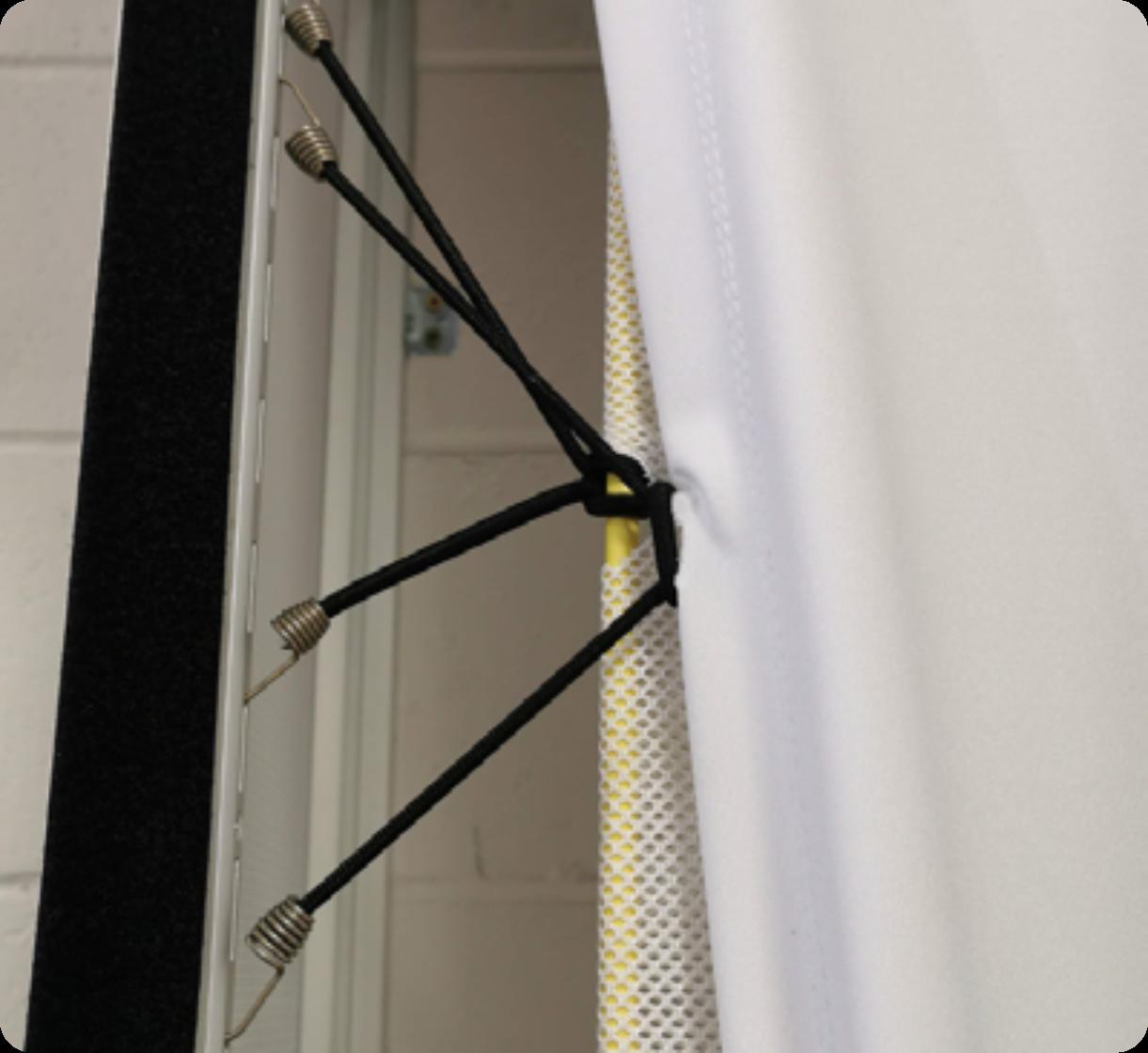
With the front of the screen facing the inside of the simulator, carefully push the screen into the space at the back, ensuring it doesnʼt catch on anything. Place a ladder in front of the screen, then locate the centre by counting the bungees. Lift this point and attach the bungee to the centre of the slotted steels. Next, secure the two top corners by attaching the hooks to the slots closest to the corners.
Step back from the screen and ensure it is positioned approximately in the centre of the opening. If it is not aligned properly, adjust the position of the centre bungee to shift the screen into the correct position.
Stage2–ImpactScreen
Once all the side bungees are attached, begin attaching the ones at the top. These should be secured with minimal tension.
A properly fitted screen should have its bottom weighted pocket positioned no higher than the turf but not touching the floor below. This allows the bottom of the screen to move freely when struck by a ball and return to its original position under gravity. Take the time to adjust the bungee tension to achieve this, as proper manipulation will ensure the screen looks great and functions correctly.
Once you are satisfied with the position and appearance of the screen, fit the top sheet using the same procedure as for the mesh screen.
EPSHD TopSheet
Impact Screen
Stage2–ImpactScreen
After completing the simulator, conduct a thorough test by hitting balls at different areas of the screen, starting gently and gradually increasing the force of your shots. This will help ensure that the ball reflections from the screen are well controlled. If any balls bounce back quickly, slightly loosen the bungees to reduce the tension on the screen.
Before using the simulator, conduct routine checks on the position of the screen and top sheet to ensure they are properly hung and in good condition. After a visual inspection, it is advisable to push the screen back by hand to confirm that the weighted pocket can swing freely without touching the ground.
SafetyInformation
Please also read the safety instructions later on in this document for further advice on ensuring the screen is at the correct tension and is always checked before play.
Stage3–Sim-in-a-BoxCladding
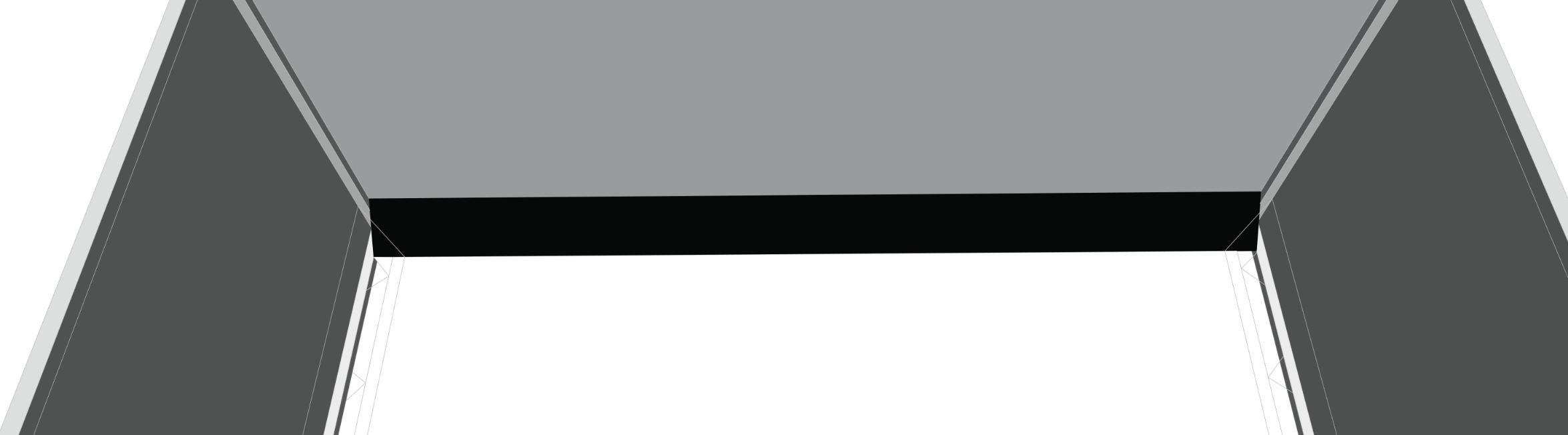
Find the Upper Protection Flap and unfold it. Measure approximately 150mm from the rear ceiling section and press the Velcro edge of the protection flap against the ceiling cladding panel. Ensure that the flap is oriented so the black fabric is facing the screen, covering the stitched pocket that holds the flexible rod.
Sim-in-a-BoxwithoutUpholsteredPanels
Find the Side Protection Flaps and apply them to the fabric of the left and right wall panels. Measure approximately 150mm from the metal upright that the screen is attached to and apply the Velcro of the side protection flap to the left and right wall panels. The flaps should sit at a 45° angle.
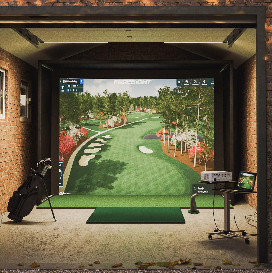
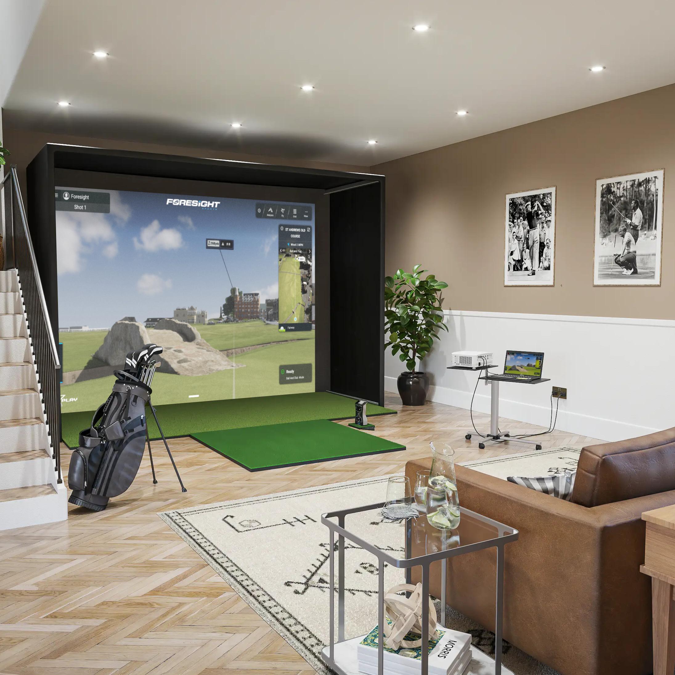
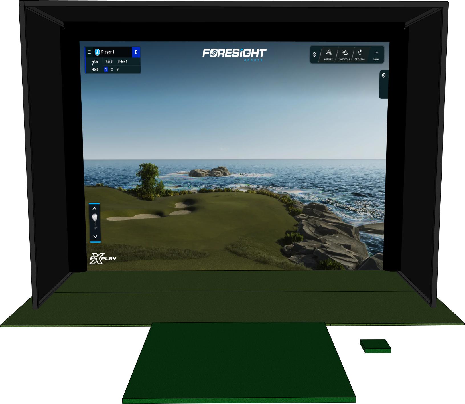
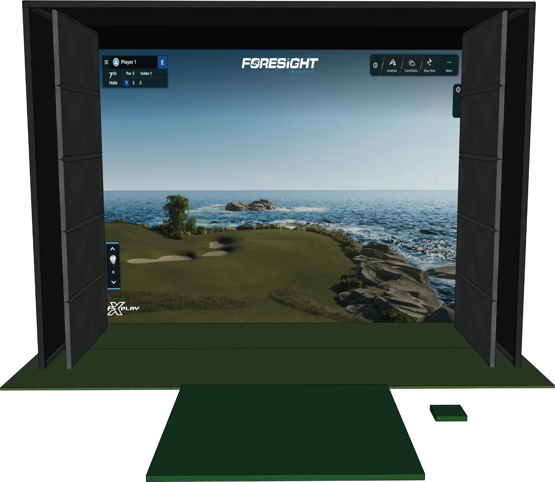
Next, unroll the hitting mat and position it along the edge of the turf, ensuring it is centred with the simulator screen. Additionally, you can roughly position the launch monitor mat as illustrated below.
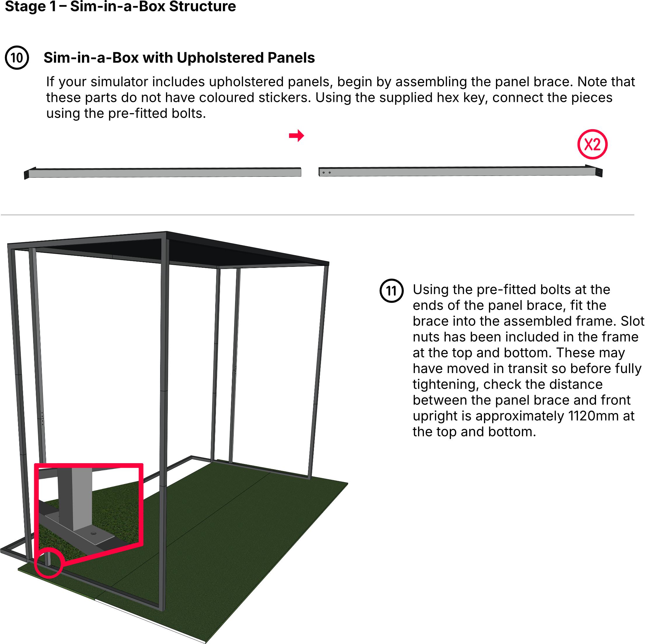
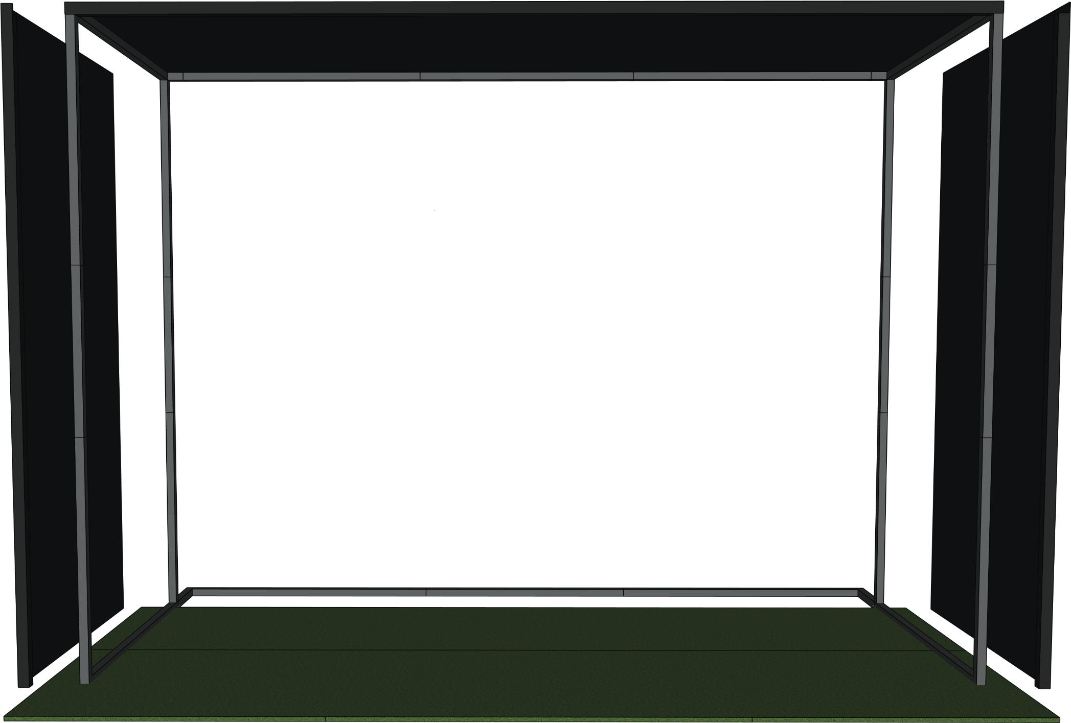
Sim-in-a-BoxwithUpholsteredPanels
For Sim-in-a-Box structures with the optional upholstered panels, you can now attach them securely using the pre-attached Velcro strips.
Stage4–LaunchMonitor
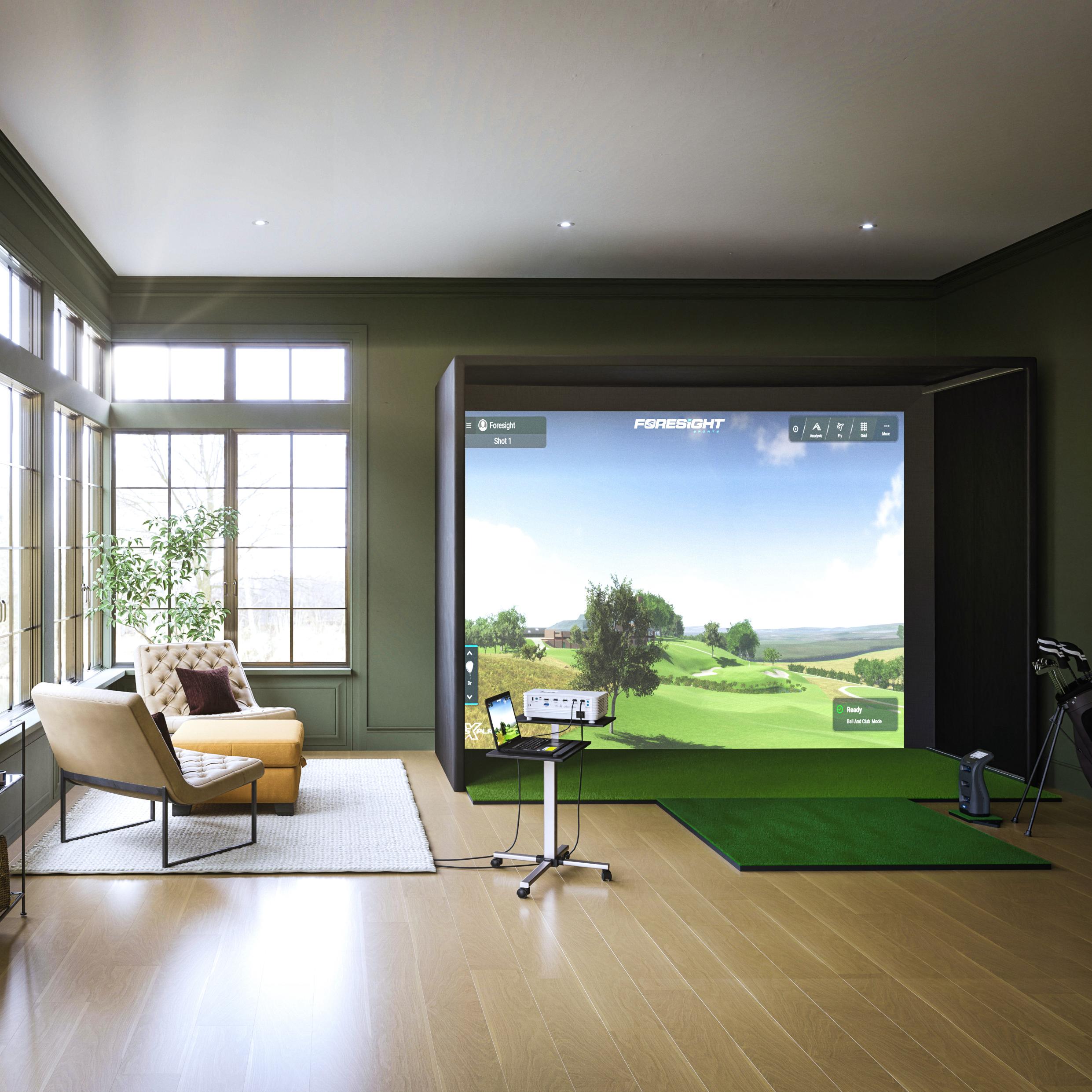
There are three main components to the Sim-in-a-Box apart from the structure itself. These are the launch monitor, the simulation laptop and the HD projector. This section will advise how these components should be installed for optimal performance.
SafetyInformation
The surge protector provided should be used to plug in all electronic components.
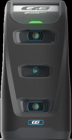
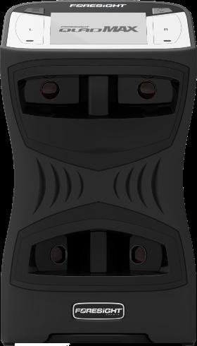
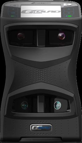
LaunchMonitor
ADDITIONALCONNECTION OPTIONS
if your package comes with the GC3, you may also connect to the computer via Ethernet or WiFi. Please see the user manual for more details.
differ from that shown)
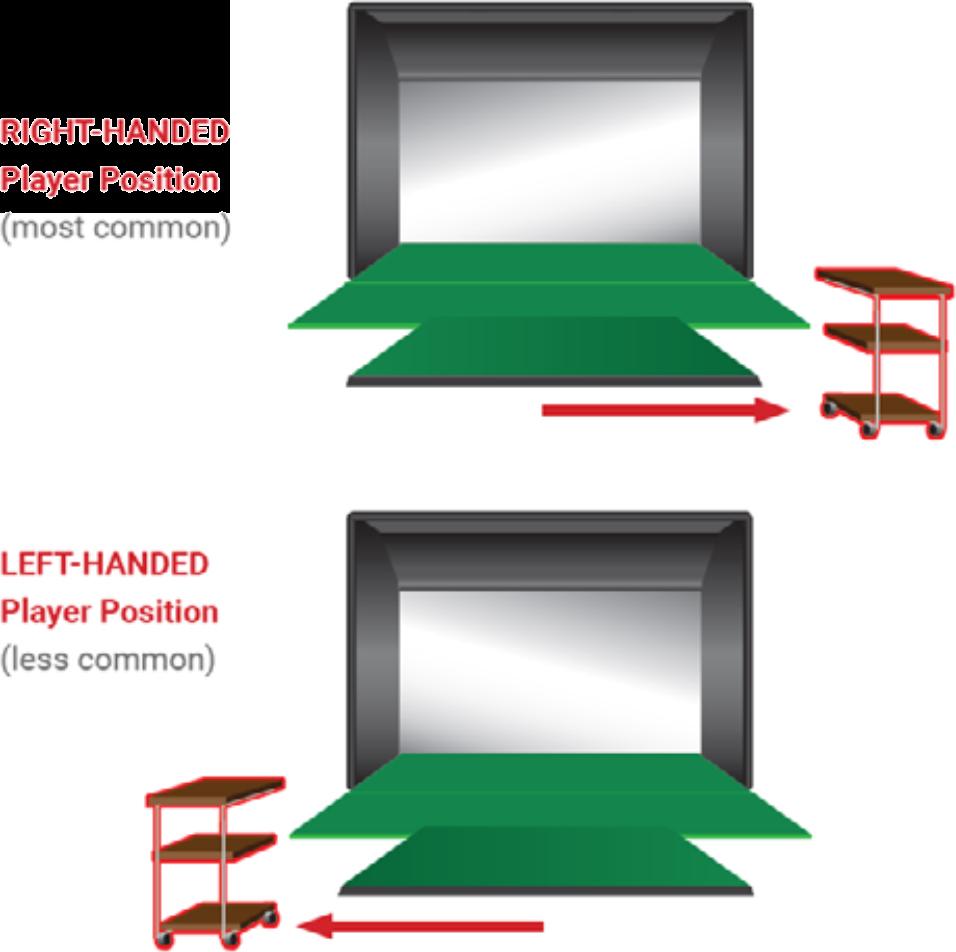
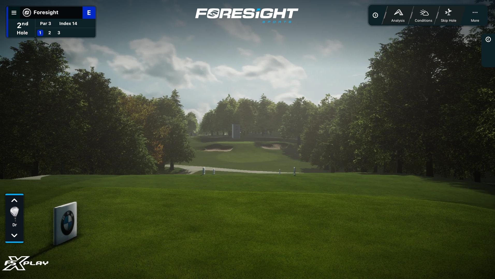
Fig. 1: Right Handed Launch Monitor Placement
Fig. 2: Launch Monitor Connection Overview (trolley may
Stage4–LaunchMonitorPlacement&Connection
Follow the instructions in the box to open your launch monitor and set it up in the desired location next to the hitting area (see Fig 1).
Our ground based launch monitors have an in-built battery which will last for approximately 4 hours of play. To operate for longer periods, it will need to be plugged into power via the power supply provided. To ensure the longevity of the unitʼs battery, it is advised not to leave it plugged in for extender periods of time i.e. overnight.
The launch monitor has three forms of connection, two wired and one wireless.
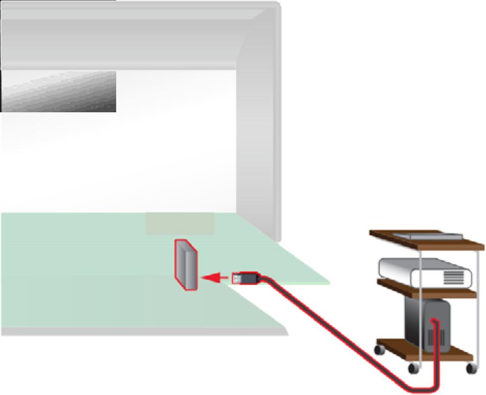
• Wired – USB – connect the launch monitor to the simulation laptop using the USB-C cable provided (see Fig 2).
• Wired – Ethernet – To enable this connection connect the female side of the adapter to the laptop ethernet port as well as the PSU. Connect the ethernet cable into the adapter and lay it to the launch monitor position. Connect the male adapter to the ethernet cable and insert the power cable and data cable into the launch monitor.
• Wireless – the launch monitor has its own Wi-Fi network which the simulation laptop can be connected to (please note that if connecting via this method you will not be able to connect the laptop to your internet Wi-Fi at the same time, and will instead need to use an ethernet cable). On the laptop open the network settings (bottom right corner of the task bar) and select your launch monitor. Enter the Security Key FSSPORTS.
In the FSX software you will be prompted to go to the Devices page of the software; when on this page you can see all available devices that are ready to connect. If you cannot see your launch monitor press the Filter button and make sure the appropriate launch monitor and connection type is selected.
Information
The following guide is for the ground based launch monitors. For ceiling mounted launch monitor setups please contact our support team.
Position the laptop and projector stand in the appropriate place according to your preferences.
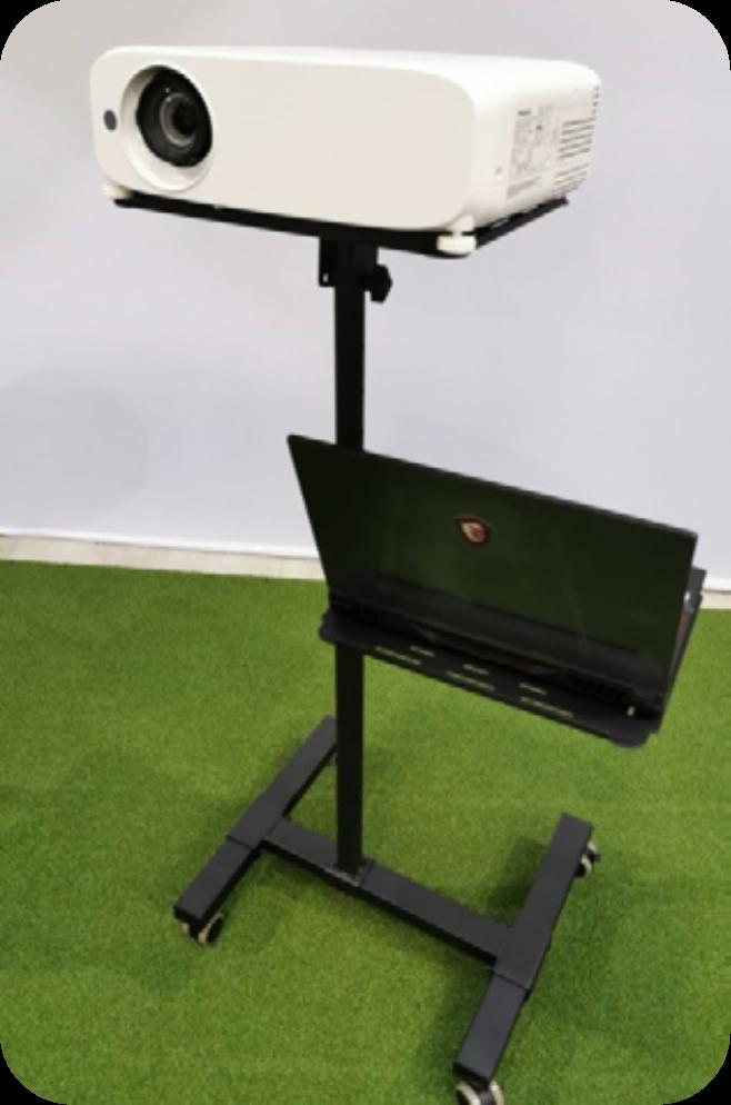
Then place the projector and laptop on the stand with the projector on the top shelf, and the laptop on the lower shelf, as shown below.
The HD projector that comes with the Performance Simulator needs to be connected to power, as well as to the laptop provided.
Always connect the projector to power via the surge protector provided.
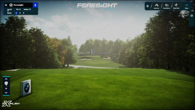
To connect the projector to the laptop simply use the HDMI cable provided. Once connected you will want to ensure the display on the laptop and the projector are the same, you can do this by pressing the windows key + P and selecting Duplicate from the list.

As the projector will be offset to one side (depending if you are a left or right-handed golfer) the image from the projector will not be straight.
Luckily our projectors come with a feature called Corner Correction which allows you to adjust each corner individually so that the image is square with the impact screen (see Fig 5).
To adjust the image via corner correction via the remote press the menu button then navigate to Screen Adjust and then Corner Correction, at which point you can adjust each corner independently to achieve the best fit.
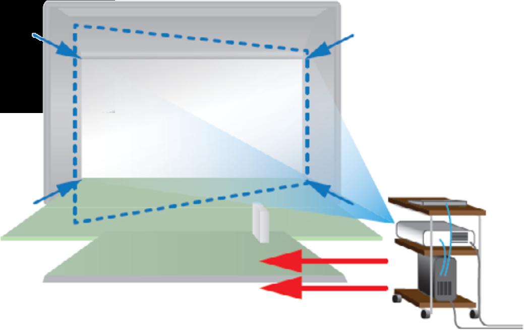
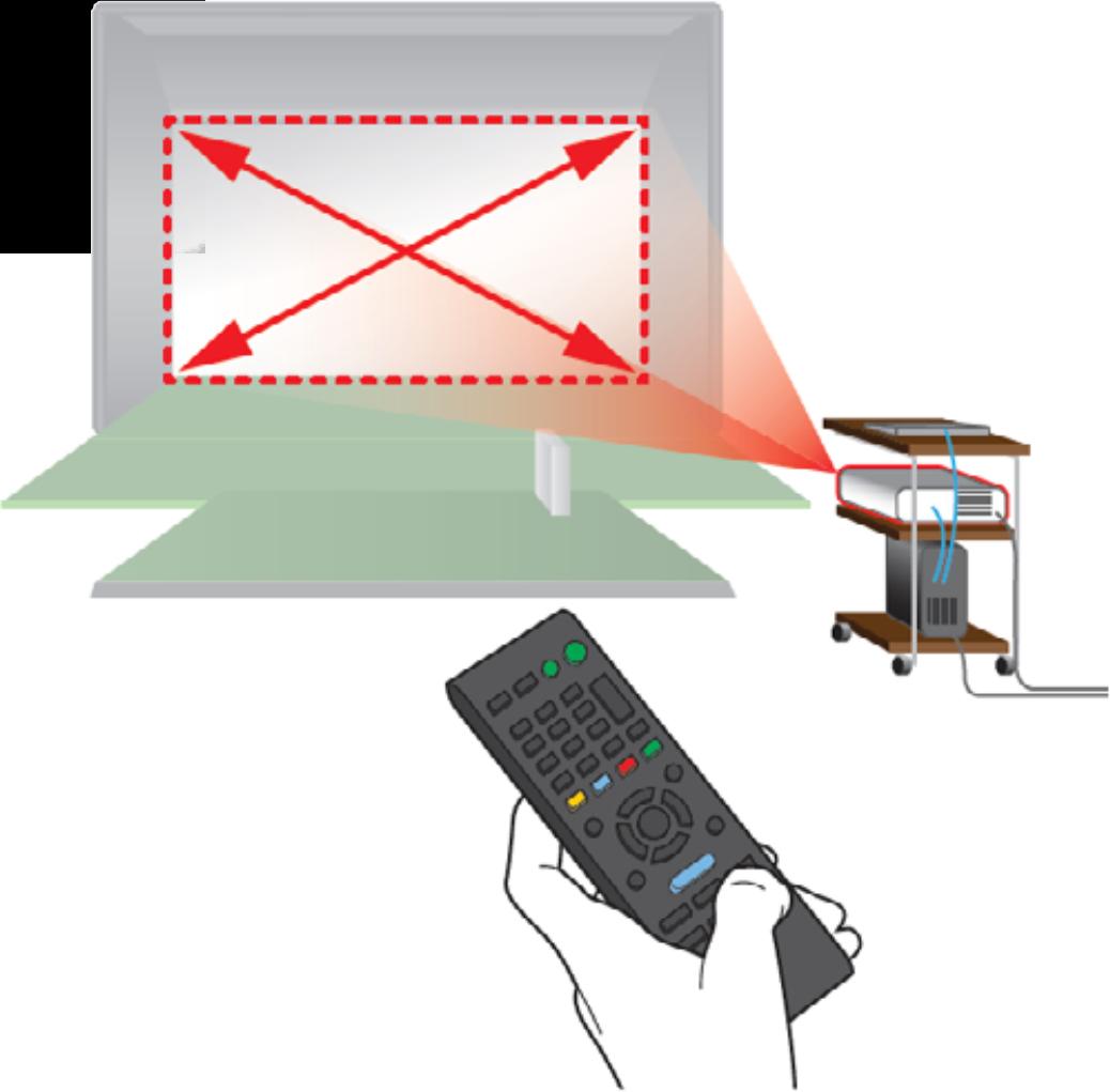

Fig. 5: Projector image upon starting (trolley may differ from that shown)
Fig. 6: Projector Image After Adjustment (trolley may differ from that shown)
Stage4–ComputerSetup
Your simulation computer comes pre-loaded with the FSX software suite, included free courses (plus any you have purchased separately), and the Fairgrounds software.
Simply turn on the laptop, plug its power supply unit into the surge protector provided, connect to your internet via Wi-Fi (or network cable) and open the FSX software. You can start enjoying a round of golf, join an online competition, or practice on the driving range.
For the optimal experience why not sign up to FSX Live? As a Foresight Sports user, you have access to a free cloud account to save all the data collected from your launch monitor. Data can be sent to the FSX Live account via the FSX software for your referral at any time. To register your account, or to access your existing account, simply visit your web portal via https://performance.foresightsports.com.
ImportantSafetyInformation
SafetyInformation
Always ensure that every player, and anyone in the golf room, is familiar with these safety guidelines BEFOREPLAY on your Foresight Sports Europe simulator.
Beforeplayinggolfalwaysensurethat:
• The simulator is installed as per the installation instructions.
• The screen is in good condition and properly fitted with the correct fixings and is correctly tensioned. The sides of the screen should ‘giveʼ when pressed and not be taut and there should be no part of the screen that is so taut that a ball would bounce back to the player with enough speed to cause any harm.
• The bottom of the screen is correctly fitted to allow proper flex, and where a weighted pocketscreen design is used that the weight hangs just off the floor of the room but is behind the turf of the simulator so that it cannot be struck.
• The screen protection strips are securely attached to the simulator cladding.
• There is nothing else within the simulator or behind the screen that golf balls could hit (the simulator should be clean and clear and have no unnecessary items in it) and that there is nothing in the playing area that the player could hit with a golf club whilst swinging.
• Golf clubs and balls are in good, clean condition with no rough spots or ‘Sharpieʼ marks (dirty or marked balls can permanently mark your hitting screen and balls that are rough or split can tear the screen).
• The hitting mat is not damaged, is in good condition, and that it is properly positioned and secured to the floor to avoid movement.
ImportantSafetyInformation
Duringplayalwaysensurethat:
• There is only one player in the simulator at any one time.
• Shots are always hit from the hitting surfaces and never further back from the hitting screen than the line of the tee, and shots are not hit so close to the front of the mat (nearest to the hitting screen) that the club could hit the turf in front of the mat.
• Shots are always hit into the simulator, as close as possible to the centre of the simulator screen, and if there is any chance of the ball not entering the simulator structure itself play should be ceased. Where situations in the software require a shot to be hit away from the centre of the screen – or where you choose to do so - ensure that the software is adjusted so that the target is central to the screen.
• Shots are not hit so high that they would miss the screen. A shot that is hit higher than the screen could bounce back and damage the room or harm the player.
• The tee is not so high as to produce a risk of ‘skyingʼ the ball.
• Always tee the ball as low as is practicable.
• Players always maintain a safe swing distance from other people in the room.
• Players and other people in the room are not intoxicated or otherwise impaired, and are fit enough and healthy enough to participate in the game.
• All people in the room pay close attention to the golf play to ensure safety.
• If players are in any doubt about the safety of play they should cease playing until it is safe to do so.
Youshouldbeawarethatplayinggolfwithrealclubsandballswithinaconfinedspaceisa controlledriskactivityandplayersdosoattheirownrisk.
Foresight Sports or Foresight Sports Europe cannot be held responsible for any issues that may occur through misuse, failure to follow the above guidance or to use reasonable common sense etc. For more detail on risk and liabilities please refer to Foresight Sports Europe Terms & Conditions of sale.
We hope you enjoy playing on your simulator, the most accurate and immersive golf simulator ever produced!
SimulatorMaintenance
Maintainingyoursimulatorisstraightforwardanddoesnotrequiremuchtime.Thiswillmaximise safetyandkeepyoursimulatorintip-topcondition.
Checkthatthepaddedframe-protectionstripsaresecurelyfixed
• Ensure that the padded frame-protection strips to the sides and above the screen are securely attached and in the correct positions.
• Ensure that secondary side-protection strips hang freely and are in good condition in order to prevent any shots hitting more than 20mm of the left hand side of the frame protection strips behind them.
Checkscreenfortearsorcuts
• Check front screen for tears or cuts and replace if necessary.
• Ensure the backing net is undamaged and replace if necessary.
Ensurethescreenishangingproperlyandthetensionisadequateforsafeplay
• The front screen and rear net are designed to be tensioned at the sides to provide a flat surface for projection. Check for any creases and/or bulges which may indicate the original fit may have changed.
• A correctly tensioned screen will have enough flex across the entire surface to prevent any shot from bouncing back towards the player at a speed that could cause any harm.
SimulatorMaintenance
Checkforcorrectmovementoftheweightedscreenpocket
• The weighted pocket at the bottom screen pocket should be very slightly raised above the floor of the room to allow it to swing unimpeded when a golf ball strikes the screen. This should be checked by gently pushing the screen at the mid-point and at each corner and confirming it returns to its original position without rubbing against the floor.
• Should the bottom of the pocket be touching the floor it will reduce the screen movement and put undue stress on the seams thereby reducing the lifespan of the screen. If the screen does need lifting, this can be achieved by detaching the top baffle to reveal the support bungees. Move the bungee hooks apart to raise the screen.
• The weighted bottom of the screen should hang just behind the floor turf.
Checkgolfballsfordamageandwear
• Check golf balls in the simulator for dirt, marks, cuts or abrasions. Damaged or marked balls WILL damage and/or mark your screen.
Checkscreen(under,tosidesandbehind)forstrayballs
• Ensure there are no balls that could cause prevent any of the safety features working properly. Carry out the check more often if required.
Inspectbungeecordsandscreenrods
• Check the bungee cords and fibreglass rods (that hold the screen in place) for fraying, damage or breakage. Replace as needed.
SimulatorMaintenance
Cleanprojectorfilterandchecklamplife
• Clean the projector filter (identify the filter vent and remove and clean filter if this is an option, or if fixed: vacuum the filter with the soft brush on a vacuum (so as not to move the projector itself).
• Check the lamp life hours to monitor lamp life and check if it might need replacing soon (although we always recommend keeping a spare handy as lamps can sometimes suddenly fail).
• Refer to the Projector Training Sheet for full details. It is vital to follow the instructions in order to ensure the image quality is maintained for as long as possible and to reduce the number of replacement lamps that you purchase – as they are not cheap.
VacuumSimulator
• Vacuum the interior of the simulator to keep it clean and tidy and also to minimise dust in the atmosphere (excessively dusty atmosphereʼs can affect the lifespan and performance of the electronic components of your simulator).
Inspectfloorturfandhittingmatfordamage
• It is important to check the floor and hitting surfaces for damage to make sure there are no trip hazards and to ensure that the hitting zone is not worn out to the extent that a player could damage themselves or their clubs.
RotateHittingMat90or180degrees
•Rotate hitting mat periodically 90 or 180 degrees to prevent excessive wear.
These pages are for reference and these images are not to scale
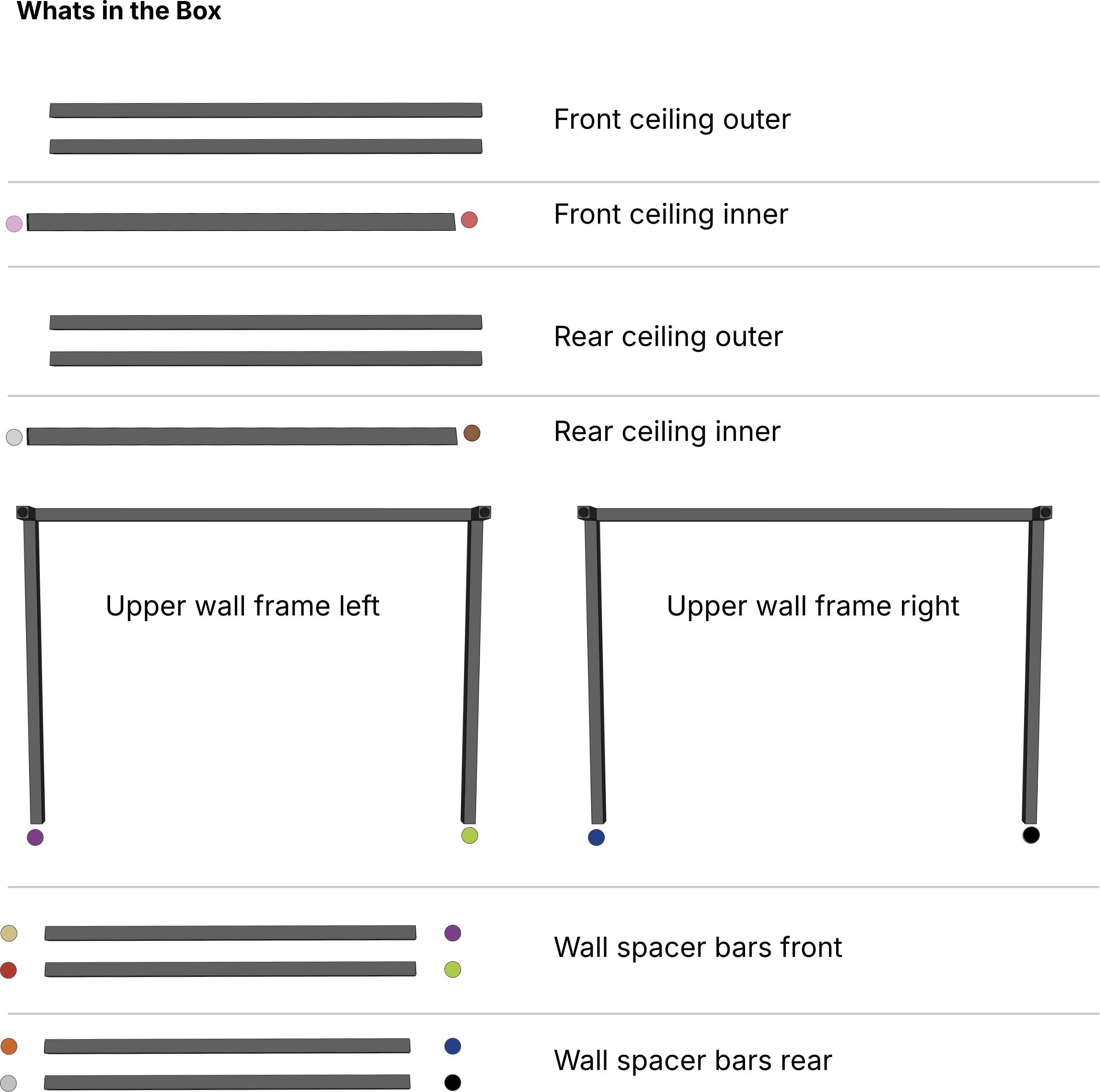
WhatsintheBox
These pages are for reference and these images are not to scale
Wall cladding panel x2
If your Sim-in-a-Box includes upholstered panels they are included
Ceiling cladding panel
WhatsintheBox
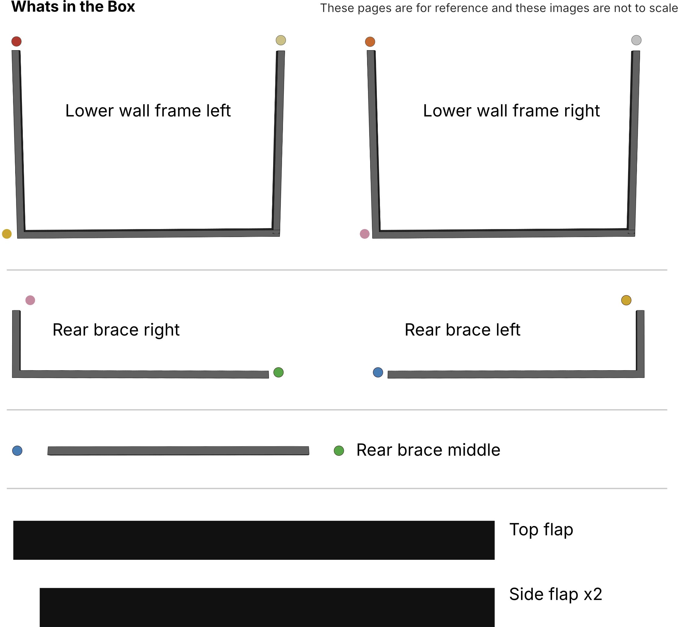
These pages are for reference and these images are not to scale
Mesh impact screen
Side screen rods
Top screen rod
Top Sheet
Bungees
WhatsintheBox
These pages are for reference and these images are not to scale
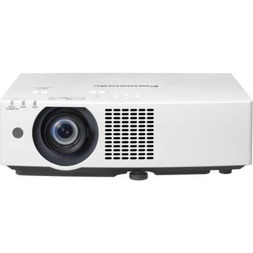
Projector

Laptop & projector stand
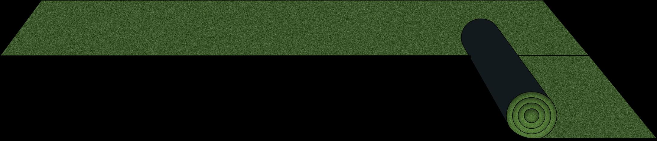
Rolls of turf x2
Hitting mat
Launch monitor mat


These pages are for reference and these images are not to scale
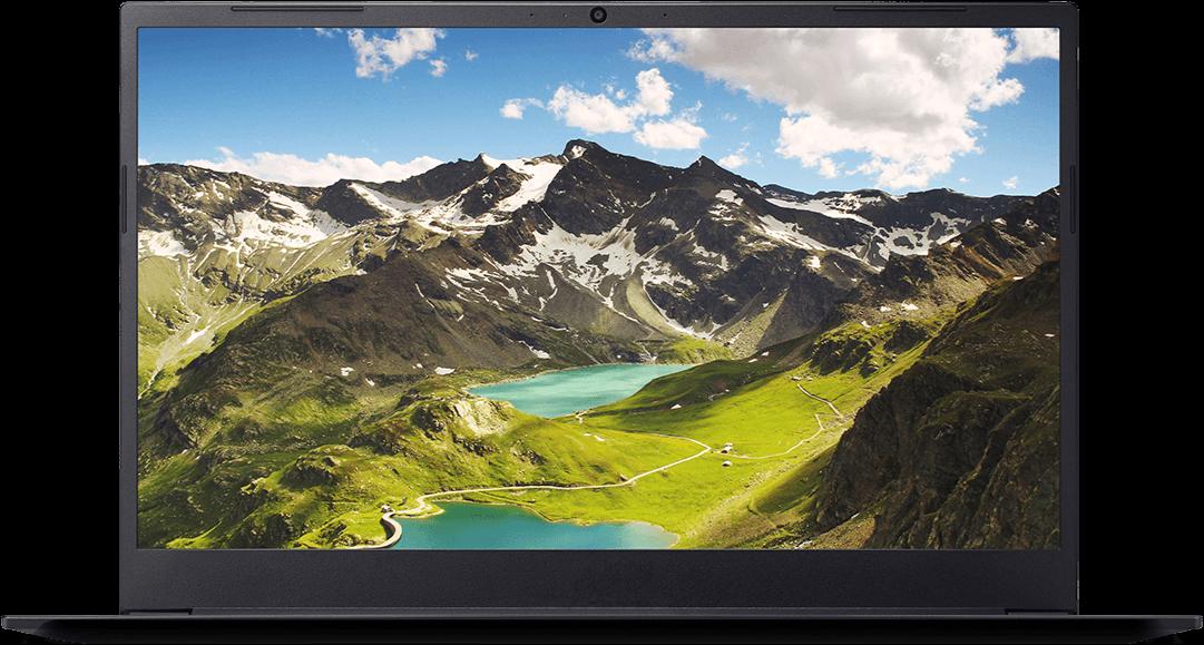
Computer Launch monitor
Otherincludeditems:
Surge Protector
USB Extender Hex Key HDMI Cable Power Cables