American Petroleum Institute: Standard 682, 4th Edition Shaft Sealing Systems for Centrifugal and Rotary Pumps
DISCLAIMER
While the FSA makes every reasonable attempt to ensure that the information contained in this document is accurate and current, the FSA, its officers, directors, volunteers, and authorized agents are not responsible for any errors or omissions contained therein nor are they responsible for any results obtained from the use of or reliance upon its content. All information is provided “AS IS,” with no guarantee of completeness, accuracy, timeliness or of the results obtained, and without warranty of any kind, express or implied. In no event shall FSA or its officers, directors, volunteers, or authorized agents be liable to you or anyone else for any decision made or action taken in reliance on the information con tained herein or for any for any consequential, indirect, special, or similar damages, even if advised of the possibility of such damages. The informa tion contained in this document is for informational purposes only and does not constitute professional advice. It also includes references to certa in standards that may change over time and should be interpreted only in light of particular circumstances. It is your sole responsibility to confi rm the current state of any referred to standards. FSA reserves the right to modify or update the document content and to modify this Disclaimer at any t ime, effective upon posting of an updated version of this Disclaimer.
This Fluid Sealing Association Knowledge Series training presentation introduces the American Petroleum Institute: Standard 682, 4th Edition. This is part of a series of presentations of this industry standard. This presentation describes API-682 seal coding system:
Seal Description
Design Options
Seal Size
Seal Support System
▪ This FSA training material is made available for informational purposes only and is made available “AS IS.” It is intended to serve only as a summary of the content of the API-682 standard and not as a substitute for or to replace or supersede the actual language of the API standard.
▪ For the full language of the API-682 standard, please refer to the actual standard and/or refer to API’s website for further information: https://www.api.org/products-and-services/standards. FSA disclaims any and all liability for any injuries or damages to persons or property resulting from reliance upon this informational summary.
Seal Code
API-682 “Annex D”
▪ The mechanical seals code provides a concise way of referring to a design and features commonly supplied with seals
▪ Used with Annex C datasheet to specify purchasing requirements of mechanical seal and sealing systems
▪ Note: Assumes all standard defaults of mechanical seal designs
Seal Code
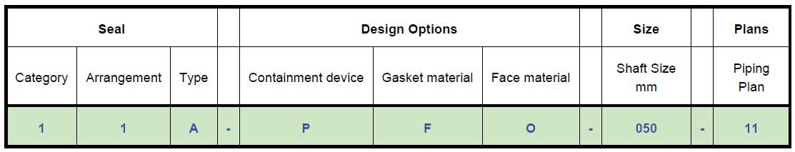
Seal code has 8 positions broken down into 4 sections
▪ First section has 3 positions describing the seal
▪ Second section has 3 positions describing the design options
▪ Third section has 1 position describing the shaft size in mm
▪ Final section has 1 position describing the seal support plan
Further information on each of these categories can be found in the Fluid Sealing Association’s Knowledgebase.
Seal Code
Section 1 describes the seal
▪ First position designates the seal category (1, 2, or 3). These categories are defined in API-682 section 4.1.2
▪ Second position designates the seal arrangement (1, 2, or 3). These arrangements are defined in section 4.1.4
▪ Third position designates the seal type (A, B, or C). These types are defined in section 4.1.3
Seal Code
Section 2 describes the seal's design options and consists of the 4th thru 6th code positions
▪ Position 4 designates the containment device found on the atmospheric side of the mechanical seal.
▪ Position 5 designates the secondary sealing element material
▪ Position 6 designates the seal face material combination
Position 4 designates the containment device type
P : Plain Gland
L : Floating throttle bushing
F : Fixed throttle bushing
C : Containment seal
S : Segmented Floating throttle bushing
X : Unspecified, for options not covered by the standard options
Seal Code
Position 5 designates the secondary sealing material
F : Fluorocarbon (FKM) elastomer gasket
G : TFE spring energized gasket
H : Nitrile elastomer gasket
I : Perfluorocarbon (FFKM) elastomer gasket
R : Flexible graphite
X : Unspecified, for options not covered by the standard options
Seal Code
Position 6 designates the seal face combination
M : Carbon vs. Nickel Tungsten-Carbide
N : Carbon vs. Silicon-Carbide
O : Silicon-Carbide vs. Nickel Tungsten-Carbide
P : Silicon-Carbide vs. Silicon-Carbide
Q : Silicon-Carbide vs. Silicon-Carbide
R : Carbon vs. Silicon-Carbide
S : Graphite Silicon-Carbide Composite vs. Silicon-Carbide
T : Graphite Silicon-Carbide Composite vs. Silicon-Carbide
X : Unspecified, for options not covered by the standard options
Seal Code
Section 3 describes the shaft size the seal cartridge will be installed on
▪ Section 3 consists of the 7th position of the seal code
▪ Shaft size is expressed millimeters
▪ Shaft size is rounded up and expressed in 3 digits
25 mm = 025
37.25 mm = 038
Seal Code
Section 4 describes the seal support systems
▪ Section 4 consists of the 8th position and describes the seal support piping plans that will be used on the seal installation.
▪ Piping plan descriptions are found in Annex G
▪ If more than 1 piping plan is used, the piping plans are listed with a forward slash "/" between them
▪ E.g.: A seal utilizing a plan 11 and a plan 53B is denoted as "11/53B"
Further Information
American Petroleum Institute Standard 682
For further information and detail please review the API 682 standards document.
Request a copy of the “API Std 682” from the API Publication