
Foreword
The Operator's Manual
You and others can be killed or seriously injured if you operate or maintain the machine without first studying the Operator's Manual. You must understand and follow the instructions in the Operator's Manual. If you do not understand anything, ask your employer or JCB dealer to explain it.
Do not operate the machine without an Operator's Manual, or if there is anything on the machine you do not understand.
Treat the Operator's Manual as part of the machine. Keep it clean and in good condition. Replace the Operator's Manual immediately if it is lost, damaged or becomes unreadable.
00 - General
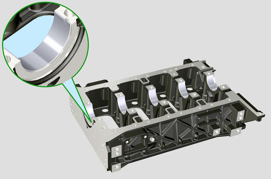
The bedplate acts as the main strength component of the engine. it maintains the correct alignment and supports the weight of the internal components.
Remove and Install
CAUTION This component is heavy. It must only be removed or handled using a suitable lifting method and device.
Before Removal
1.This procedure requires service parts. Make sure you have obtained the correct service parts before you start, refer to Parts Catalogue.
2.Make sure that the engine is safe to work on. If the engine has been running, let it cool before you start the service work.
3.Get access to the engine.
4.Remove the drive belt.
Refer to: PIL 15-18-03.
5.Remove the oil sump.
Refer to: PIL 15-45-00.
6.Remove the turbocharger(if installed).
7.Remove the exhaust manifold.
Refer to: PIL 18-24-04.
8.Remove the starter motor.
Refer to: PIL 15-75-00.
9.Remove the flywheel housing.
Refer to: PIL 15-54-03.
10.Remove the crankshaft rear oil seal flange.
Refer to: PIL 15-12-09.
11.Remove the EGR (Exhaust Gas Recirculation) (if installed).
12.Remove the inlet manifold.
Refer to: PIL 18-24-03.
13.Disconnect and remove the high and low pressure fuel pipes.
Refer to: PIL 18-96-00.
14.Remove the timing gear front case.
Refer to: PIL 15-51-21.
15.Remove the fuel injection pump.
Refer to: PIL 18-18-15.
16.Remove the fuel injection drive gear.
Refer to: PIL 15-51-00.
17.Remove the intermediate drive gear.
Refer to: PIL 15-51-00.
18.Remove the high duty PTO (Power Take-Off) device (if installed).
19.Remove the fuel injectors.
Refer to: PIL 18-18-03.
20.Remove the rocker cover.
Refer to: PIL 15-42-06.
21.Remove the rocker assembly including the push rods
Refer to: PIL 15-42-00.
22.It is not necessary to remove the cylinder head assembly to remove the bedplate. If however, the cylinder head needs to be removed for other reasons (for piston and connecting rod removal for example) remove it now.
Refer to: PIL 15-06-00.
23.Position the engine upside down in a suitable jig or fixture, supported at the front of the crankcase.
Remove
1.Remove the main bearing bolts in the sequence shown.

Figure 155.
2.Remove the bedplate peripheral bolts in the sequence shown.
C
3.Carefully separate the bedplate from the crankcase. Use suitable lifting equipment (if the bedplate is lifted manually, two people will be required). Do not use a lever to separate the bedplate.
4.Carefully remove the lower bearing shells from the bedplate.
sure that all the necessary tools, bolts etc. are readily available prior to assembling the components. The parts must be installed and tightened to the correct torque value within 5min minutes (with a maximum permissible time of 15min).
Important: Before installing the bedplate: Do not rotate the crankshaft. Make sure that the upper main bearing shells are flush with the bottom face of the crankcase.

Install
Important: The crankshaft half bearings are made of special material. Therefore, they must be replaced every time they are removed to prevent seizures. The lower and upper crankshaft half bearings cannot be replaced singularly, and both halves must be replaced together.
1.Make sure that all items are clean and free from damage and corrosion.
2.Use a suitable degreasing agent to clean both sides of the lower bearing shells.
Consumable: Cleaner/Degreaser - General purpose solvent based parts cleaner
3.Install the lower bearing shells into the bedplate. Make sure that the reference notches are at the correct location.
A Bedplate
D Lower bearing shells (x5)
Before Installation
1.Clean off all traces of the old sealant compound from the crankcase and bedplate mating faces.
2.Use a suitable degreasing agent to carefully clean the main bearing saddles in the bedplate and crankcase. Take care not to block the oil ways or the piston cooling jets.
Consumable: Cleaner/Degreaser - General purpose solvent based parts cleaner
Important: Anaerobic sealant will not start to cure whilst it is open to the atmosphere, however when air is excluded (for instance when the two parts are put together) it will immediately start to harden. Make
A Bedplate
D Lower bearing shells (x5)
E Reference notch
4.Lubricate the lower bearing shells with clean engine oil.
5.Install the two shoulder half-rings onto the lower crankcase. Apply two dots of ITP GX100 grease to hold the rings in position.
D Lower bearing shells (x5)
F Shoulder half-rings (x2)
G Guide pins
6.Applya1.0mm(0.04in)thickbeadofLoctite5188 around the crankcase/bedplate mating face as shown.
12.Install the bedplate peripheral bolts (x17).
13.Tighten the bolts to the correct torque value in two stages. Strictly follow the torque sequence shown.
H Crankcase
J Loctite 5188
K Oil feed holes
L Return oil grooves
7.Make sure that you do not block the oil feed holes and the return oil grooves.
8.Assemble the bedplate to the crankcase. Make sure that the guide pins on the crankcase are engaged properly in the slots on the bedplate.
9.Note: The bedplate is heavy. Two people will be required to lift and rotate the bedplate safely on to the crankcase.
10.Install the main bearing bolts (x10).
11.Tighten the bolts to the correct torque value in three stages. Strictly follow the torque sequence shown.
Important: If the parts have not been tightened to the correct torque value within the maximum 15min time period, then the parts must be separated, thoroughly cleaned and fresh sealant should be applied.
After Installation
1.Check that the crankshaft can be freely rotated by hand.

2.Measure the crankshaft end float. Make sure that the end float is between 0.18mm (0.007in) and 0.38mm (0.015in).
3.Carry out the procedures listed in the 'Before Removal' section in reverse order.

Table 63. Torque Values
Technical Data
(1) No visible damage/wear or marks
Component Identification
Figure 164.
Operation Lubrication
Oil is fed from the main gallery via five drillings, one to each of the main bearings. A groove around the diameter of the upper main bearing shell allows oil
transfer to cross drillings in the crankshaft to feed each of the big end bearings. Crankshaft gear is 'splash'lubricated.Frontandrearcrankshaftoilseals prevent oil leakage from, and dirt ingress to, the engine.

Check (Condition)
1.Checkthemainbearingsurfacesfordamageand excessive wear.
2.Measure the crankshaft diameters to confirm they are within service limits. Refer to: PIL 15-12-00.
3.Check that the oilway cross drillings in the crankshaft are clear and free from debris.
Blocked or restricted oilways will cause oil starvation at the big end bearings.
4.Check that the piston cooling oil sprayers are clear (if installed). If the sprayers cannot be cleared remove the fixing screws. Remove the sprayers and discard them.
C
E
B
D
03 - Main Bearing
Introduction
In a piston engine, the main bearings are the bearings on which the crankshaft rotates.
The bearings hold the crankshaft in place and prevent the forces created by the piston and transmitted to the crankshaft by the connecting rods from dislodging the crankshaft, instead forcing the crank to convert the reciprocating movement into rotation.
Check (Condition)
1.Check the bearing shell surfaces for signs of damage and excessive wear.
2.Measure the crank pin diameters to confirm they are within service limits.
Refer to: PIL 15-33-00.
3.Measurethebearingjournaldiameterstoconfirm they are within service limits.
Refer to: PIL 15-12-00.
4.Replace any parts that are worn or not within the specified tolerances.
Remove and Install
Special Tools
Before Removal
1.This procedure requires service parts. Make sure you have obtained the correct service parts before you start, refer to Parts Catalogue.
2.Make sure that the engine is safe to work on. If the engine has been running, let it cool before you start the service work.
3.Get access to the engine.
4.Remove the fuel injectors. Refer to: PIL 18-18-03.
5.Remove the rocker cover. Refer to: PIL 15-42-06.
6.Drain the oil from the engine. Refer to: PIL 15-00-00.
7.Remove the oil sump. Refer to: PIL 15-45-00.
8.Position the engine upside down in a suitable jig or fixture, supported at the front of the crankcase.
Important: The connecting rod and the main bearing cap have been fracture split and must be kept together as a set. Utmost care must be taken to avoid contamination and or damage to the fracture split surfaces.
1 Piston rings
2 Piston
3 Connecting rod
4 Main bearing cap
5 Bolts
6 Big end bearing shells
Z Fracture split surfaces
1.Itisrecommendedthatthemainbearingcapsare removed in pairs according to the firing cycle.
1.1.Cylinder 2
1.2.Cylinders 1 and 3
2.Putmarksonthemainbearingcapstomakesure that they are installed in their original positions on assembly.
3.Rotate the crankshaft so that the main bearing caps on cylinder 2 are positioned at the top.
4.Remove the bolts and lift off the main bearing caps from the connecting rods.
5.Make sure that the bolts are not used again. Discard the bolts.
1 Main bearing caps
2 Main bearing cap bolts
6.Remove the bearing shells.
6.1.Lift out the bearing shells from the main bearing caps.
6.2.Carefully rotate the crank to disengage from the connecting rods and gain access to the upper bearing shells.
6.3.Lift out the upper bearing shells.
6.4.The bearing shells must be replaced every time they are removed.
7.Carefully rotate the crankshaft to position the main bearing caps of cylinders 1 and 3.
8.Make sure that the crankshaft does not hit the connecting rod of cylinder 2.
9.Do the steps 4 to 6 to remove the bearing caps and bearing shells for cylinders 1 and 3.
10.Inspect the main bearings for signs of damage and excessive wear.
Refer to: PIL 15-12-03.
Install
1.Replacement is the reversal of the removal procedure.
2.Make sure that all items are clean and free from damage and corrosion.
3.Install the upper bearing shell to the connecting rod. Lubricate the bearing shell with clean engine oil.
4.Install the lower bearing shell to the main bearing cap.Lubricatethebearingshellwithcleanengine oil.
5.Use compressed air to clean the fracture surfaces of the main bearing caps before assembly.
6.Install the main bearing cap to the connecting rod.
7.Replace the fixing bolts.
8.Tighten the new bolts in two stages to the correct torque value.
Special Tool: Torque Wrench (10-100Nm) (Qty.: 1)
9.Make sure that the crankshaft rotates smoothly and the connecting rods have axial play.
10.After you perform the check, rotate the crankshaft to position the first cylinder at TDC (Top Dead Centre)
After Installation
1.Install the oil sump. Refer to: PIL 15-45-00.
2.Install the rocker cover. Refer to: PIL 15-42-06.
3.Install the fuel injectors. Refer to: PIL 18-18-03.
4.Fill the engine with engine oil. Refer to: PIL 15-00-00.
06 - Front Oil Seal
Remove and Install
Special Tools
Description Part No. Qty.
Crankshaft Front Oil Seal Installation Tool
Before Removal
892/01157 1
1.This procedure requires service parts. Make sure you have obtained the correct service parts before you start, refer to Parts Catalogue.
2.Make sure that the engine is safe to work on. If the engine has been running, let it cool before you start the service work.
3.Get access to the engine.
4.Remove the drive belt, refer to (PIL 15-18).
5.Remove the crankshaft pulley, refer to (PIL 15-12-12).
Remove
1.Use a suitable lever behind the lip of the seal, carefully prise out the oil seal from the counterbore in the crankcase. Take care not to scratch or damage the counterbore or the crankshaft hub. Damaged or dirty sealing faces will cause the oil seal to fail.
A Crankshaft oil seal
B Crankcase
C Crankshaft hub
Install
B
C A
1.Make sure that the counterbore and the crankshaft hub are clean and free from damage and corrosion. Use a suitable degreasing agent to clean all traces of oil and grease from the counterbore.Important:Theoilsealhasaspecial coating and MUST be installed dry without lubricant.
2.Dismantle the seal installation tool. Bolt the centre body to the crankshaft hub, using the bolts. Refer to Figure 171.
Special Tool: Crankshaft Front Oil Seal Installation Tool (Qty.: 1)
3.Install the oil seal on to the centre body. Make sure that the seal is installed the correct way around. Assemble the outer sleeve on to the centre body and install the screw. Refer to Figure 171.
A Crankshaft oil seal
C Crankshaft hub
E Fixing bolts (x3)
G Outer sleeve
4.Turn the screw to push the seal squarely into the counterbore until the outer sleeve comes up against the front edge of the counterbore. Whencorrectlyinstalled,thefrontfaceoftheseal should be flush with the edge of the counterbore within the specified tolerance. Refer to Figure 172.
Dimension: -0.5 -0/+0.5mm
B Crankcase
D Seal installation tool
F Centre body
H Screw
A Crankshaft oil seal
B Crankcase
C Crankshaft hub
F Centre body
G Outer sleeve
5.Remove the seal installation tool.
After Installation
1.Install the crankshaft pulley, refer to (PIL 15-12-12).
2.Install the drive belt, refer to (PIL 15-18).
12 - Pulley
Remove and Install
Special Tools
Install
1.The installation procedure is the opposite of the removal procedure. Additionally do the following steps.
Before Removal
993/70111 1
Description Part No. Qty. Torque Wrench (10-100Nm)
1.This procedure requires service parts. Make sure you have obtained the correct service parts before you start, refer to Parts Catalogue.
2.Make sure that the engine is safe to work on. If the engine has been running, let it cool before you start the service work.
3.Get access to the engine.
4.Remove the drive belt. Refer to (PIL 15-18).
Remove
1.Remove the fixing bolts and withdraw the pulley from the crankshaft.
Figure 173.
2.Make sure that all items are clean and free from damage and corrosion.
3.Renew the fixing bolts. Tighten the new bolts in three stages to the correct torque value. Special Tool: Torque Wrench (10-100Nm) (Qty.: 1)
4.The bolts are tightened using a torque and angle method. Refer to Fasteners and Fixings, General, Introduction (PIL 72-00).
Figure 174.
A Crankshaft pulley
B Fixing bolts (x3)
2.The bolts must not be reused. Discard the bolts.
C Angle gauge (obtain locally)
After Replacement
1.Install the drive belt. Refer to (PIL 15-18).
Table 66.
15 - Phonic Wheel Introduction
The crankshaft position sensor is installed on the timing gear case. The sensor reads the signal from the phonic wheel that is installed on the engine pulley. The sensor sends an analogue signal to the ECM (Engine Control Module). The sensor produces a 5V square wave signal with Hall effect when the motor is rotating. This data, together with the signal from the sensor, allows the ECM to control the fuel injection with respect to the TDC (Top Dead Centre) of the piston.
For gap adjustment. Refer to: PIL 15-84-00.
Suggest:
If the above button click is invalid.
Please download this document first, and then click the above link to download the complete manual.
Thank you so much for reading

21 - Tensioner
Remove and Install
This procedure is applicable for machines installed with Poly-V drive belt.


Important: The drive belt must always be replaced every time it is removed, even if it has not reached the scheduled hours for replacement.
Remove
1.Make the machine safe.
Refer to: PIL 01-03-27.
2.Remove the drive belt.
Refer to: PIL 15-18-03.
3.Remove the tensioning screw.
4.Remove the screw that secures the tightening pulley.
5.Remove the tightening pulley.
5.Install the tightening screw on to the plate, up to the stop on the pulley pin.
6.Tension the drive belt.
A Tensioning screw
B Screw
C Tightening pulley
Install
1.Insert the screw in the tightening pulley.
2.Manually tighten the screw on to the pulley pin up to the stop; Loosen the screw again by one turn.
3.The screw must be out by the specified distance from the surface of the tightening pulley.
Distance: 32mm
4.Install the drive belt.
Refer to: PIL 15-18-03.
A Tensioning screw
B Screw
C Tightening pulley
D Pulley pin
E 32mm