
TABLE OF CONTENTS
Template Name: SM_1_col Template Date: 1997_01_13
BALLASTING THE STX TRACTOR FOR OPTIMUM PERFORMANCE
Preparing the STX Series Tractor for full load, continuous duty work operations and for optimum field performance requires that a logical sequence of procedures be followed BEFORE adding ballast.
A tractors field operating weight should be determined by the operation to be performed and local soil conditions. Front-to-rear weight ratios are critical to tractor performance. The lighter the tractor, the more productive it will be, assuming the balance is correct and it is heavy enough to pull the load without excessive traction loss. Proper tire inflation is another important part of the tractor performance equation.
The objective in preparing a tractor for optimum continuous full load field operation is to:
1.Create the correct load distribution between the front and rear axles.
2.Allow operation at the desired implement working depth and travel speed within an acceptable rate of wheel slip.
3.Maintain engine speed within the rated RPM range during field operation.
4.Minimize rolling resistance and soil compaction.
5.Reduce tire wear.
6.Enhance ride control.
Operators who pull lighter loads at faster speeds do more work, increase efficiency and reduce soil compaction. STX Series Tractors are more efficient and productive at field speeds of 8 KPH (5 MPH) and higher.
Operating at these speeds provides longer life for drive train components and tires. An implement that cannot be pulled at the desired working depth at 8 KPH (5 MPH) or higher at rated engine speed is not properly matched to the tractor.
DO NOT overweight the tractor to pull very heavy loads. If the tractor is overweighted and pulls heavy loads for an extended period of time in the lower gears (below 6 KPM or 4 MPH), drive train life expectancy could be reduced. It is important to remember that as full load field speed decreases, torque increases. As torque increases, gear loading and wear accelerate rapidly, shortening drive train life.
A properly matched tractor and implement will increase power train component life and reduce service costs. An overweight tractor has increased rolling resistance, which causes increased soil compaction and fuel consumption. (Rolling resistance consumes horsepower).
A tractor that is too light permits excessive traction loss, wasted horsepower, and accelerated tire and drive train wear.
The tractor should always be weighted to match LOCAL field conditions to control slip and OPTIMIZE tractor performance. Traction varies within a wide range of soil conditions.
Field experience has shown that just small adjustments to tractor weight split, ballast type, and tire inflation pressure can optimize the tractor for the work application and result in improved productivity. Correct weighting and tire inflation pressures will provide the following benefits:
• Increased Productivity
• Reduced Soil Compaction
• Improve Flotation
• Improved Ride
• Reduced Tire Wear
• Extend Power Train Life
• Better Fuel Efficiency
LOADS MATCHED TO TRACTOR
The best performance occurs when wheel slip for STX tractors equipped with bias ply tires is 8% to 12% and 5% to 8% for tractors equipped with radial tires set to the manufacturers recommended load inflation pressures. The optimum slip range for QUADTRAC tractors in average field conditions is 2% to 5%.
NOTE: The STX QUADTRAC tractors DO NOT require additional ballast for normal farming operations.
Operation within this range will provide the best fuel economy, performance and tire life while increasing field productivity. Proper ballasting and tire inflation procedures will optimize the tractors performance. Proper weighting WILL NOT provide a remedy for implements that are simply too large for the tractor. If the engine speed falls below the normal operating RPM range and wheel slip percentage is not above the recommended operating range, adding ballast WILL NOT improve tractor performance.
Adding weight to the tractor will improve performance only when:
• Engine speed is within the normal operating range; and wheel slip exceeds recommended guidelines.
One of the most important considerations in field operations is the amount of horsepower available at the drawbar or hitch. Power to move a tractor that is overweight will result in less power available to pull the load.
Excessive ballast can also shorten drive train component life. Pulling a full load in a gear that gives continuous duty cycle speed below 6 KPH (4 MPH) causes accelerated gear wear. Use no more ballast than necessary to pull the load at the desired working speed above 8 KPH (5 MPH). Remember:
• Never add weight until you are sure it is required.
• Remove weight if not required for lighter loads.
Operating a tractor with too much weight can cause the following:
• Waste Fuel
• Reduce Available Drawbar Horsepower
• Increase Soil Compaction
• Increase Tire Wear
• Reduce Productivity
• Shorten Power Train Life
• Increase Operating Costs
IMPORTANT: The total tractor weight with all equipment, and ballast weight must never be more than the maximum recommended gross operating weight for continuous duty work applications.
Template Name: SM_1_col
Template Date: 1997_01_13
DETERMINING WHEEL SLIP
BEFORE adding weight, first determine if weight is needed. The best way to determine the need for weight is to monitor percent of slip during actual field operation.
If the tractor is equipped with a true ground speed sensor, percent of slip will be calculated and displayed on the Optional Performance Monitor Display. Refer to the Operators Manual for more information on the STX wheel slip display feature.
Template Name: SM_1_col
Template Date: 1997_01_13
TIRE AVERAGE ROLLING RADIUS CHART
The tire rolling radius numbers shown in the following chart represents the calculated rolling radius for various tire sizes and manufacturers. The actual rolling radius can vary a small amount depending on tire inflation pressure, tire wear and tractor weight. Use the following code numbers if it should become necessary to program the Display Monitor.
Dynamic Rolling Radius
The actual rolling radius can vary a small amount depending on tire pressure, tire wear and the weight and load on the tractor.
If a higher degree of accuracy is required, dynamic rolling radius can be established as follows:
1.Put a mark on the side of the tractor tire.
2.Operate the fully loaded tractor on a dry flat surface.
3.Count ten (10) revolutions of the wheel.
4.Measure the distance traveled in inches divided by an Engineering constant (62.83).
5.Use the following formula to determine the dynamic rolling radius. Dynamic Rolling Radius = Distance
Use the dynamic rolling radius as specified in Step 5 of the tire radius calibration.
MEASURING WHEEL SLIP WITHOUT TRUE GROUND SPEED SENSOR
If the tractor is not equipped with a true ground speed sensor, measure the amount of wheel slip as follows:
1.Put a reference mark on the side of the tractor rear tire.
2.Operate the tractor with the implement in the ground.
3.While the tractor is moving put a marker on the ground, outside the implement width, where the reference mark on the tire comes down to the ground.
4.Continue to move along with the tractor and count ten wheel revolutions. Put a second marker on the ground outside the implement width, where the reference mark on the tire comes down to the ground for the tenth time.
5.Lift the implement out of the ground. Put the tractor in position and put a new reference mark on the rear tire aligned with the first ground marker.
6.Operate the tractor, with the implement raised, from the first ground marker to the second ground marker. Count the number of wheel revolutions between the two ground markers.
Find the percent of slip as follows:
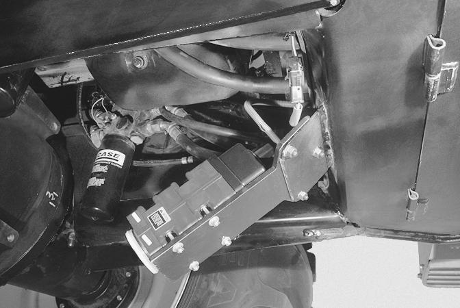
NOTE: When too much ballast is installed on the tractor, you will see the clear shape of the tire tread in the ground which is an indication of no slippage. With too little ballast, the tire tread marks will not show because of the tire slippage. 382L9
Too Much BallastCorrect BallastToo Little Ballast
The ideal wheel slip percentage range is 5 to 8 percent for radial tires. If average wheel slip is measured within this range at the desired travel speed, no weight is required. If average wheel slip measures less than the minimum recommended percentage of slip, remove weight. If wheel slip is excessive add weight in the proper distribution ratio. Add no more weight than is required to pull the load at the desired working speed within the recommended wheel slip range.
Template Name: SM_1_col
TRACTOR STATIC WEIGHT DISTRIBUTION
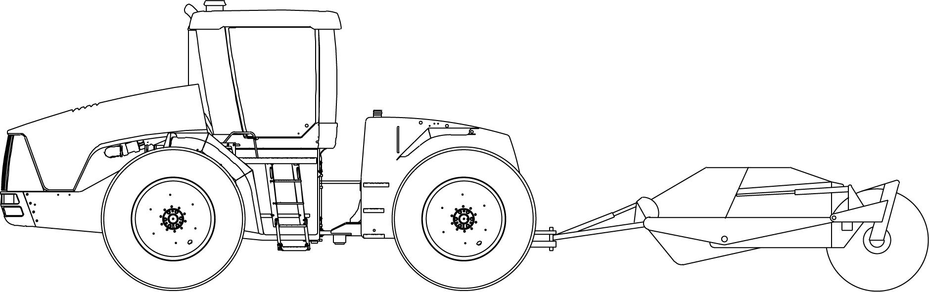
DRAWBAR TOWED HIGH DRAFT IMPLEMENTS
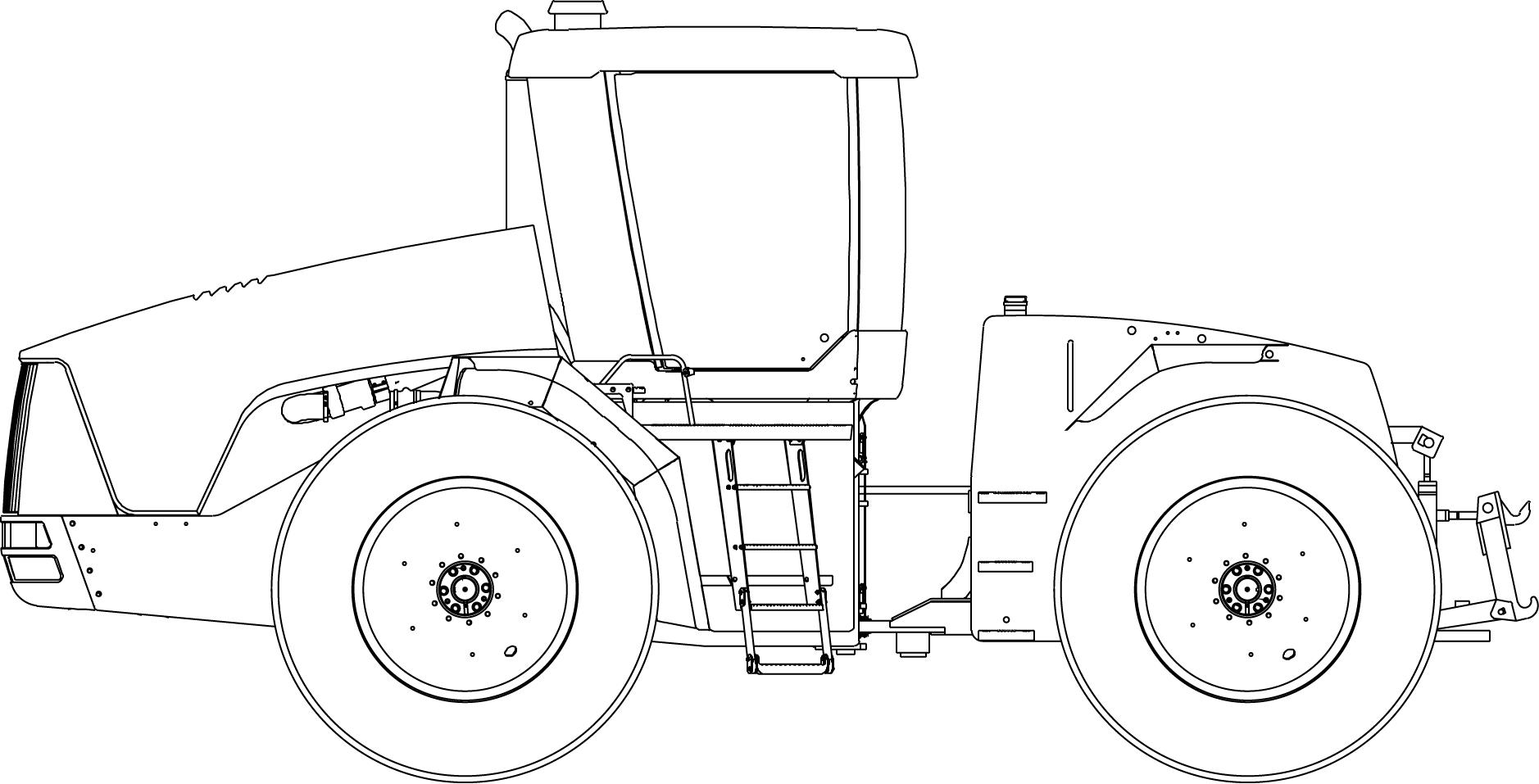
HITCH MOUNTED IMPLEMENTS
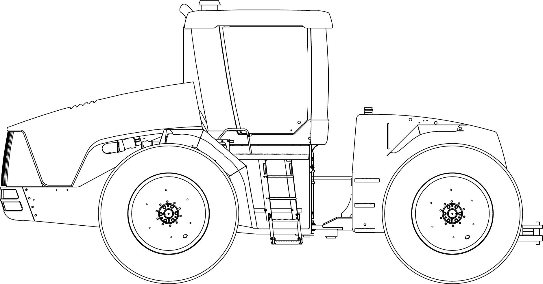
IMPLEMENTS WITH HEAVY VERTICAL DRAWBAR LOADS
Suggest:
If the above button click is invalid.
Please download this document first, and then click the above link to download the complete manual.
Thank you so much for reading

Template Name: SM_1_col Template Date: 1997_01_13
TRACTOR STATIC WEIGHT DISTRIBUTION
To obtain optimum tractor performance for each type of field operation, specific guidelines must be followed. The major items to be considered are:
1.Total tractor weight and static weight split (% of static weight on the front and on the rear axles)
2.Tire inflation pressures.
There may be times when it is desirable to weight the tractor to decrease slippage and/or increase balance and stability. There are many factors that affect traction and balance that must be considered before adding weight, such as:
• Type of operation (tillage, planting, etc.)
• Soil conditions and terrain (hillside)
• Type of implement
• Draft load of implement
• Tires (size, type, pressure, single or dual)
• Tractor static weight distribution
Three different levels of operating applications and weighting categories are recommended as follows:
A DRAWBAR TOWED HIGH DRAFT IMPLEMENT (disks, chisel plows, field cultivators, towed rippers etc.)
B HITCH MOUNTED IMPLEMENTS (rollover plows, mounted rippers, row crop cultivators etc.)
C TOWED IMPLEMENTS WITH HEAVY VERTICAL DRAWBAR LOADS (scrapers, potato and beet harvesters, planters, grain carts etc.)
The best method of determining the tractor static weight split ratio is by scale weighing a fully equipped tractor. Tractor weights can and do vary with options, tire/wheel equipment and other operational equipment.
Static weight distribution ratios are based upon the total weight of a fully equipped tractor (including ballast or other attached equipment). Weight split ratios are calculated without the implements or attachments connected to the tractor.
IMPORTANT: The front and rear weight split distribution ratio ( ± 2%) must be maintained whenever adding or removing weight.